Teknatool SuperNova User manual

Teknatool International Ltd
65 The Concourse, Henderson, Auckland, New Zealand
Website: www.teknatool.com
Email: [email protected]
Phone: 0064-9-837 6900
Fax: 0064-9-837 6901
© Copyright Teknatool International 2000, 2003
Teknatool Publication No. 95-0324-005
READ THIS MANUAL CAREFULLY AND
BECOME THOROUGHLY FAMILIAR WITH
CHUCK OPERATIONS BEFORE USE
SuperNova™
Geared Chuck
Manual

2
Thank you for purchasing our Teknatool SuperNova Geared Chuck. We are confident it will help to
both enhance and advance your woodturning. The Teknatool SuperNova Chuck is a very versatile
unit, designed to offer a wide range of workholding modes. The SuperNova has a powerful grip while
being quick and easy to use.
It combines the best features of our Nova Chuck and similar woodturning chucks (wide jaw
movement, quick two way grip) with the advantages of the Tuff Lock geared action (Patent App.
314589) which gives significantly enhanced gripping power and a convenient one handed operation.
The SuperNova also has some special safety features: a travel stop on the jaws and a contracting
scroll jaw action to centre under power with no work mounted. This means that there is very little
chance of the jaws flying out of the chuck - a common hazard with many chucks.
The SuperNova Chuck can accept a wide variety of add on accessory jaws. These jaws are specially
designed to expand into recesses or contract around round/square wood spigots of varying sizes
and applications. Some irregular pieces can also be gripped. The chuck can swap from the
expansion/dovetail mode to the spigot mode and back instantly, with no adjustments or extra fittings
being necessary. In both modes, any spigot or recess size can be selected between the minimum
and maximum range of the jaws. With the add-on accessory jaws removed, the jaw slides can be
used to grip quite small spigots. The chuck also utilises a powerful Woodworm screw for screw
chuck work.
The SuperNova is very adaptable and is designed to accept a range of accessories to further extend
its use. These accessories are included at the back of this manual. However the range is steadily
being expanded to include more options. Check with your reseller for the latest accessories, or see
our website on http://www.teknatool.com.
As a valued customer, we would be pleased to hear from you and how you found your SuperNova.
Any comments on the chuck or accessory ideas would be very welcome so that we can continue to
offer what we believe is the best woodturning chucking system available.
ACCURACY: The SuperNova Chucks are sample tested from each batch and are made to run within
the following tolerance limits:
Face Runout Maximum: 0.1mm (0.0039 inch)
Radial Runout Maximum: 0.13mm (0.005 inch)
The testing is performed with the chuck mounted on a standard insert. To ensure accuracy when
mounted on a lathe, refer to page 6. It is well to note that wood is quite a plastic material - with
different densities even in the same piece, and liable to warp out of place while turning. This is a part
of the beauty and appeal of working with such a medium. However, under these circumstances
pursuing accuracies as quoted above can be very difficult to achieve. For most woodturning
situations (with some expectations) there is little need to achieve such tolerances.
CONTENTS PAGE
INTRODUCTION 2
SAFETY RULES 3
SUPERNOVA MODELS 4
CHUCK OPERATION 4
SUPERNOVA PARTS DIAGRAM 5
MOUNTING CHUCK ON LATHE 6
MAINTENANCE, STOP ON JAW TRAVEL, JAW SLIDES, INSERTION OF JAW SLIDES 8
MOUNTING 50mm JAWS, OPERATING MODES 9
DOVETAIL OPERATION, FORMING RECESS 10
SPIGOT OPERATION 11
TROUBLE SHOOTING GUIDE 12
OPTIONAL ACCESSORIES 13
WARRANTY 15

SAFETY
DANGER: THIS CHUCK IS CAPABLE OF CONTRIBUTING TO SERIOUS INJURY, AS WITH ANY
OTHER POWERTOOL ACCESSORY, IF USED IMPROPERLY ON THE LATHE.
Before using the SuperNova Chuck, read and understand this instruction manual. Read and
understand also the lathe owner's manual. If you do not have a manual, contact the supplier of
your lathe to obtain one before using the lathe and Chuck.
User must be professionally trained to use this chuck. Vocational school courses recommended.
As with other chucking methods, an extremely cautious and sensible approach is necessary. With the
SuperNova Chuck it is not possible to give exact directions as to the amount of tightening pressure
required for workholding. Follow closely strict guidelines in this manual for different jaw types on wood
blank diameters and length, plus turning speed.
BEFORE USING SUPERNOVA CHUCK MAKE SURE THAT -
• ALWAYS WEAR EYE PROTECTION WHICH COMPLIES WITH CURRENT ANSI STANDARD Z87.1
(USA). WE RECOMMEND THAT A FULL FACE SHIELD BE USED AT ALL TIMES.
• Chuck is properly secured on lathe spindle. Follow mounting instructions for your lathe for faceplates
and other spindle fixtures.
• For safety, DO NOT ROTATE CHUCK UNDER POWER WITHOUT WOOD BEING GRIPPED.
•WARNING: EXCESSIVE SPEED IS A SERIOUS LATHE HAZARD. ALWAYS TURN AT THE SLOWEST
SPEED POSSIBLE.
• Speed will vary with wood blank size. The larger the blank the slower the speed. Consult your lathe
manual or lathe information plate for speed guidelines.
• DO NOT ATTEMPT TO USE THE CHUCK UNLESS THE LATHE SPEEDS ARE KNOWN, YOU MUST
STRICTLY FOLLOW THE MAXIMUM SPEED LIMITS SET OUT IN THE OPERATING SECTION OF
THIS MANUAL. DO NOT EXCEED THEM UNDER ANY CIRCUMSTANCES.
• EXAMINE WOOD CAREFULLY. ONLY MOUNT WOOD THAT IS SOUND, If any cracks, splits, or
weakness is found in wood - DO NOT MOUNT ON CHUCK. DO NOT MOUNT ANY WOOD THAT IS
LIKELY TO BREAK UP DURING TURNING (E.G. ROTTEN OR SPONGY WOOD). DO NOT USE
POORLY JOINTED/LAMINATED WOOD.
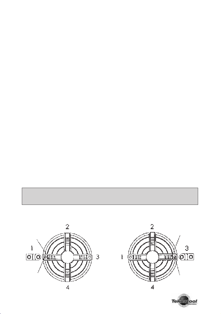
• Make sure wood is clamped firmly. Follow mounting instructions for different gripping modes and jaw
types. In the expansion mode do not use undue force or jaws may split the wood.
• Do not exceed maximum guidelines in this manual for wood blank diameters/length set out in this
manual for different modes and jaw types. DO NOT USE WITH ANY COPYTURNER OPERATIONS
• Check wood is securely held in chuck, before operation. Check grip by vigorously wrenching wood
blank back and forth. If any loosening occurs, re-examine holding area for adequate grip (Following
mounting guidelines) and any damage to holding area. Rotate manually to make sure of clearance
before switching power on.
• WARNING FOR SAFE OPERATION. DO NOT EXTEND JAW SLIDES BEYOND CHUCK BODY UNDER
ANY CIRCUMSTANCES. ONLY OPERATE CHUCK WITH JAW SLIDE STOP SCREW IN PLACE AND
TEST TO MAKE SURE IT IS ADJUSTED OUT TO STOP JAW SLIDE.
• This prevents jaw slides from dislodging from chuck.
• Irregular or out of balance stock needs to be turned at the slowest possible speed until it is in
balance. For use on outboard/left-hand rotation -
• MAKE SURE INSERT IS SECURELY LOCKED WITH GRUBSCREW BEFORE USE. Use only hand
held woodturning chisels to shape wood being held in chuck.
• USE THE RIGHT CHISEL FOR THE JOB AND DO NOT FORCE TOOLS. Use safe and commonly
approved chisel techniques. Wherever possible stand to one side of the revolving wood.
• WEAR PROPER CLOTHING. Do not wear any loose clothing, neck ties, gloves, bracelets, rings or other
jewellery that could get caught in moving parts. Wear protective hair covering to contain long hair.
• DRUGS, ALCOHOL, MEDICATION. Do not operate chuck or lathe while under the influence of drugs,
alcohol or any medication.
• KEEP CHILDREN AND VISITORS AWAY. All children and visitors should be kept safe distance from
the work area.
Make workshop childproof with padlocks, master switches, or by removing starter keys.
3

4
If not engaged properly tightening power will be reduced and could result in damage to gear teeth.
TO CONTRACT JAWS:
Turn the handle in an anti clockwise direction to contract the jaws.
When the action takes up against the piece held give an extra nip up so jaws securely engage with wood.
TO EXPAND JAWS:
Turn the handle in a clockwise direction to expand jaws.
When the action takes up against the piece held give an extra nip up so jaws securely engage with wood.
EUROPE/UK only: Stop screw will restrict all maximum jaw action, contracting and expanding, by
approx. 6mm (1/4”). Includes all accessory jaws.
NOTE:
These directions are the opposite action to other common appliances e.g. water taps.
To enable you to get used to the action it would be useful to mark directions on the chuck body
until you get used to them.
The reason they are opposite is an extra safety feature incorporated in the SuperNova:
The jaws with no work held will, because of the gear direction tend, to track to centre with using the
inboard spindle (the most common situation). This is an extra safeguard to prevent the jaws flying out of
the chuck should the stop screw, for some reason, not be in place.
SUPERNOVA MODELS
There are three models of the SuperNova Chuck designed to meet various woodturning requirements.
Note that inserts, accessories etc are fully interchangeable between the Nova and SuperNova Chucks.
COMPANION MODEL:
The Companion Sui Model is a stripped down version for those who already have the Nova Chuck. The
kit is without the Woodworm screw, 50mm standard jaws and Allen keys etc which the woodturner would
have as part of their Nova Chuck kit. Comes with a complementary set of jaw screws to mount any Nova
Chuck accessory jaws.
Companion Accessory Kit: 1x M6 Grubscrew, 2 x Fibre washers, 1 x pinion handle, 8 x M6x10 Jaws
screws, SuperNova Chuck Manual.
STANDARD MODEL:
The Standard SuperNova has a similar kit option to the Nova Chuck. This kit has both the Woodworm
screw for screw chucking and the general-purpose 50mm standard jaws.
Standard Accessory Kit: 1x M6 Grubscrew, 2 x Fibre washers, 1 x pinion handle, 8 x M6x10 Jaws
screws, 1 x Woodworm screw, 1 x 50mm jaw set, 1 x M4 Allen key 1 x M3 Allen key, SuperNova Chuck
Manual.
PREMIER MODEL:
This has a special Powergrip add on jaw set for heavy-duty spigot turning and heavy bowl work. These
jaws really match the tremendous gripping power of the Superior Chuck.
Premier Accessory Kit: Ix M6 Grubscrew, 2 x Fibre washers, I x pinion handle, 8 x M6x10 Jaws screws,
1 x Woodworm screw, 1 x Powergrip jaw set, 1 x M4 Allen key, 1 x M3 Allen key, Superior Chuck Manual.
CHUCK OPERATION
Adjustment: A handled chuck pinion key is provided for adjustment of chuck action. Please refer to
FIGURE 1 on page 5 for location of the two key positions.
TO OPERATE JAWS:
Insert the pinion key into one of the two 22mm guide holes in the SuperNova body.
IMPORTANT!! MAKE SURE THE PINION GEAR IS FULLY HOME AND ENGAGED WITH THE SCROLL
GEAR. TO RETAIN ENGAGEMENT MAINTAIN A SLIGHT DOWNWARD PRESSURE ON HANDLE SO
THAT THE END OF THE PINION IS ALWAYS LOCATED IN THE HOLE ON THE CHUCK BOSS.

5
1. Thread Insert (Insert version only)
2. Circlip (retains scroll ring)
3. Scroll Ring with Tuff Lock Gears
4. Swivel Pinion Handle
5. SuperNova Body
6. Safety Stop Screw
7. ‘1’ identifies No. 1 Slide position
8. Jaw slice (set of four slides)
9. 50mm add on Jaw segment
10. M6 x 10mm set screws (8)
11. M4 Allen Key
12. Woodworm Screw
13. Batch No.
14. Fibre Washer
15. M6 x 6 Grubscrew locks insert into body
16. M3 Allen Key
17. 1 1/2” HexSpanner to unwind insert not supplied

MOUNTING CHUCK ON LATHE
There are two versions of the SuperNova Chuck: an insert version for all threads up to 27mm (1 1/8”)
and threaded versions for dedicated threads up to 38mm (1 1/2”).
CORRECT MOUNTING OF CHUCK TO INSERT (WITH INSERT VERSION) AND LATHE SPINDLE IS
VERY IMPORTANT TO ACHIEVE ACCURACY.
INSERT VERSION: Check that the correct insert has been supplied to match your lathe spindle thread.
The code of the insert is on a label on the plastic insert cover and stamped on one of the flats of the
hexagon section of the insert.
A list of thread sizes that can be fitted with an insert plus the larger dedicated threads is provided
below. If you find your lathe thread is not listed, check with your supplier (or at www.teknatool.com) to
see if there have been more recent additions to the thread range. Failing that, you may have a blank
insert or blank chuck machined to your requirements at your own expense.
WE STRONGLY RECOMMEND THAT THE CHUCK IS NOT USED ON LATHE SPINDLES UNDER
16mm (5/8”).
Threads covered by the Insert System (Threads up to 28mm (1 1/8”)
Insert 2 (12NS) : M20 X 2 Tyme Cub
Insert 3 (13NS) : M20 x 1.5 Electra Beckum Multico Sumaro
Insert 5 (15NS) : 3/4” 16TPI UNF RH 1/8” spigot
Insert 6 (I6NS) : 3/4” Plain Bore
Insert 7 (I7NS) : 1 1/8” UN RH
Insert 8 (18NS) : 7/8” 12 UN Left-hand
Insert 9 (19NS) : 3/4” 16TPI UNF RH 6mm register
Insert A (IANS) : 3/4” 14TPI BSP RH Teknatool (Pre 1986)
Insert B (IBNS) : 3/4” 14TPI BSP LH Teknatool (Pre 1986)
Insert C (ICNS) : 1” 10 TPI BSF PH Teknatool Woodfast Durden
Insert D (IDNS) : 1 8TPI UNC RH General Rockwell Delta Golding
Insert E (IENS) : 1 1/4” 12TPI RH Myford MLS
Insert F (IFNS) : 5/8” Pcmarc
Insert G (IGNS) : 3/4” 16TPI UNF RH Sears Coronet Minor/Minor
Insert H (IHNS) : 3/4” IOTPI BSW PH Rockwell Homecraft
Insert I (HNS) : M24 x 3 RH B Line Arundel K600 K450
Insert J (IJNS) : 1 1/8” 12TPI RH Myford Mystro
Insert K (IKNS) : M18 x 2.5 ELU DB180
Insert L (ILNS) : 1 1/4” 8TPI UNS RH (for DVR lathes with this thread only)
Insert M (IMNS) : 1” 10 TPI BSF LH Teknatool Woodfast Durden
Insert N (INNS) : Blank. Can be threaded up to 28mm (1 1/8”)
Insert O (IONS) : 1 1/U” BSW PH Morton
Insert Q (IONS) : M30 x 3.5 RH Teknatool Nova 3000 / Cornet / TL 1500 Woodfast,
Vicmarc
Insert T (ITNS) : 1” 8 TPI LH/RH Dual Threaded, Nova Mercury
Insert U (1UNS) : 1 1/8” UNF RH Taiwanese
Insert V (IVNS) : 7/8” 14TPI NF RH
Insert W (IWNS) : M25x2 RH Tyme Avon
Insert Y (IYNS) : 1 1/4” 8TPI UNS Teknatool Nova 3000/Comet (USA), Woodfast USA
Threads Direct to Chuck Body (cannot be changed once cut)
D Chuck (SNCD) : 1” 8TPI UNC RH Note: Maximum spindle length 25.4mm
4 Chuck (SNC4) : M33x3.5 RH
P Chuck (SNCP) : 1 1/2” BSW RH/LH Dual Threaded. Tanner Union Graduate
Wackin Bursgreen
R Chuck (SNCR) : Blank. For threads up to 38mm
X Chuck (SNCX) : 1 1/2” 8TPI NF Conover
6

7
FITTING TO CHUCK:
Check that the internal spigot of chuck body plus insert
threads are clean and that the spigot end of the insert is
free from damage. Any dents or nicks must be carefully
filed off so the insert can be fully screwed home in chuck
body. Refer to FIGURE 2.
The tolerances of the chuck body and insert are a tight fit
to ensure accuracy. This means that the insert may be
difficult at first to engage with the chuck body thread. One
way is to grip the chuck body in a vice (pad against
damage) and screw in insert using the optional accessory
spanner or a 1 1/2” AF spanner. Care needs to be taken
that the outer male insert thread is engaged properly at the
start with the female body thread. Screw insert fully into
body recess. This is important to ensure running. Refer to
FIGURE 2.
CHUCK INSERT SPANNER:
An optional, accessory insert spanner can be purchased
to help wind the inserts into the chuck ro remove from the
lathe spindle. (Code 23014). See back of manual for
further information.
The Insert can now be locked to chuck body by means of the M6 x 6 grubscrew provided. Make
sure that the fibre washer is inserted first to act as a buffer between the grubscrew and insert thread.
DO NOT SCREW IN GRUBSCREW BEFORE INSERT IS SCREWED HOME IN CHUCK.
IMPORTANT: LH THREAD INSERTS MUST BE LOCKED TO CHUCK BODY OR CHUCK BODY
COULD UNWIND FROM INSERT.
FITTING CHUCK TO LATHE:
Correct fitting of chuck to lathe spindle is important to ensure accuracy. The chuck body must
contact an accurate shoulder on the lathe spindle or bearings (as on Teknatool Nova 3000) to ensure
chuck will run true.
There can be a wide variety of lathe spindle thread and spigot dimensions even within the same
thread size. The internal thread size is kept to standard tolerances. The internal thread length and
spigots of Nova inserts are manufactured to cover as wide a range of variations as possible. This
will mean that in most situations you should be able to get a satisfactory match.
CHECK THE FOLLOWING:
Although the insert may screw on part way it may not contact properly with spindle spigot - a spacer
or some further modification of the insert may be necessary. This would be the responsibility of the
chuck user. Make sure the chuck is screwed to lathe thread properly -a good check is to see whether
it screws home on the spindle the same as another lathe fixture such as a faceplate.
POOR FIT OF CHUCK TO LATHE SPINDLE CREATES A SERIOUS HAZARD WHERE CHUCK
COULD DISLODGE FROM LATHE. DO NOT ATTEMPT TO USE CHUCK UNLESS THE CHUCK
US CORRECTLY FITTED TO LATHE SPINDLE.
Body Internal Spindle
Lathe Spindle
On lathe must mate against accurate datum
surface/shoulder NO Gap
Check insert is
fully home
- NO gap

MAINTENANCE
CLEANING CHUCK: Inspect chuck periodically for buildup of wood dust inside scroll and cavity of
chuck body. Wood dust build up can make the jaws difficult to move. To clean out the wood dust
build up, the following method can be used. Remove Jaw Slides. (First removing stop screw as
explained in previous section) then using a piece of wood (match stick size) insert in the bottom of
scroll and rotate scroll ring. This will scrape out build up of wood dust.
To disassemble chuck: (Refer to exploded chuck diagram, Page 5).
1. Use expanding circlip pliers to remove circlip securing scroll. The scroll can then be removed and
the jaws slipped out of the chuck.
2. Clean scroll and jaws with kerosene. Dry with cloth and lightly oil components. Do not over oil as
this will cause a more rapid build up of wood dust again. After cleaning - to reassemble, replace
scroll and secure with circlip.
3. Re insert jaw slides as per instructions.
4. Remember to replace jaw travel stop screw.
STOP ON JAW TRAVEL:
Stop screw is located at the end of the number 1 slideway (or no. 3 for Europe) in the body section of
the chuck. The stop on no.3 slideway for Europe is to conform to CE regulations to limit the travel of the
jaw slides to the diameter of the chuck body. The screw is removed for disassembly it must be replaced
before use. Refer exploded view FIGURE 1 on page 5 of the manual, and to drawing accompanying
insertion of jaw slides below.
JAW SLIDES
Caution: Do not close jaw slides to a diameter less than 8mm (5/16”) for workholding. Do not close jaw
slides to fully closed position because jaw slides could over travel on scroll and become disengaged.
INSERTION OF JAW SLIDES
Jaw slides are numbered 1 - 4 (numbering on end of slide). (Note: Travel stop screw at the end of
No.1 body slide needs to be removed. Refer to previous jaw slide travel lock section). When the jaws
are removed from the body they need to be reset in sequence. To reset jaws in chuck body, rotate
with pinion gear until the lead of the scroll (like a thin wedge) appears in the opening of the slide way
with ‘1’ marked beside it. (For Nova chucks with ‘1’ not marked on chuck face, any slideway may
be selected. Refer to Diagrams.
CAUTION: IT IS IMPORTANT TO ROTATE THE LEADING EDGE OF THE SCROLL BACK
SLIGHTLY TO CLEAR THE SLIDEWAY BEFORE SLIDE CAN BE INSERTED. FAILURE TO
ROTATE THE SCROLL BACK COULD RESULT IN DAMAGE TO SCROLL.
Now insert No. 1 slide into slideway and rotate scroll in a clockwise direction (chuck facing you) until the
lead of the scroll appears at the next slideway. Now engage No. 2 scroll in the same manner as No. 1.
Proceed in the same way in a clockwise sequence with No.3 and No.4 slides. Refer to figures 3 & 4.
8
Lead of Scroll
Lead of Scroll
Travel Stop Screw Travel Stop Screw

MOUNTING 50mm JAWS
The standard SuperNova Chuck is provided with 50mm
add-on jaws. They need to be located and screwed on to
the jaw slides of the chuck. The same procedure outlined
below must be followed for all accessory jaws as well.
IT IS IMPORTANT TO LOCATE JAWS PROPERLY IN THE
JAW SLIDES FOR THE CHUCK TO FUNCTION
ACCURATELY. Refer to FIGURE 5.
Follow the method set out below -
1. You will notice that the back of the jaws have a stepped location ring. This location ring is
designed to fit into the grooved section of the jaw slide for precision location. Ensure that the
slide and collet back are clean and free from any burrs or damage that might affect location.
Place the jaw segment over the hole positions on the jaw. Press the jaw segment firmly onto the
jaw slide. For the first few times you may need to GENTLY tap the jaws into the locator slot with
a block of wood.
2. The screws can now be screwed in, using the 4mm Allen Key provided. Lightly grease or oil
screws under each head and on the threads before use to prevent the screws from seizing in the
jaw. Preferably use an anti-seize compound e.g. ROCOL J 166 Anti-Seize Compound. Do all
screws up finger tight and then back them off one quarter to half a turn.
3. Wind the mounted jaws into the centre of the chuck until they all butt against the other. Now
finally tighten screws, starting with centre screws and then outside screws. Nip screws up firmly
but DO NOT OVERTIGHTEN.
4. Check there is no light between jaw slides and add on jaw segments or that one or more
segments is not higher or lower than the rest. If this is the case repeat procedure above.
OPERATING MODES
SCREW CHUCK: This is a convenient mounting method. The woodworm
screw is purpose-designed for screw chucking. It is a cylindrical screw which
maintains its full holding power along the whole length, unlike normal tapered
screws. The thin thread form is specially designed to cause minimum damage
to wood fibres. They grip better than screws with thicker threads because
there is a larger volume of undamaged wood retained within the screw.
The woodworm screw is made complete with the boss section in one piece. The woodworm screw
is designed to be used with the 50mm jaws remaining in place on the chuck. This facility is very
convenient for remounting work directly onto the jaws after the screw is removed.
To convert to this operation, place the boss section into the centre of the chuck making sure flat
shanks are aligned to the jaw slides and close jaws around it. BEFORE FINAL TIGHTENING MAKE
SURE THAT THE FRONT OF THE BOSS SECTION OF THE SCREW IS SEATED BEHIND AND
AGAINST THE 50mm JAWS. This will prevent any tendency for the boss section to creep forward
when the screw is being used.
The front face of the 50mm jaws has been machined to provide an accurate backing surface. This
is quite an advantage, providing a much tighter fit and better tolerance for irregular face stock. This
feature is also quite an advantage when using the screw to mount a bowl for first stage bowl turning
- forming the outside of the bowl straight onto the jaws (the screw is first removed) after the recess
has been formed.
SCREW DEPTH: The screw provides 19mm (3/4 inch) of thread beyond the 50mm jaws. With all
wood blocks over 150mm (6 inches) in diameter the full thread depth of 19mm should be used.
Irregular, rough tree blanks (e.g. small sections of tree limbs) not exceeding the above sizes can be
held quite firmly BUT caution must be exercised. Check for adequate contact.
CAPACITY: DO NOT USE THE SCREW FOR VERY LARGE WOOD BLANKS. Its use is intended for
small bowl and screw chucking work. The maximum capacity which should be mounted on the
screw - 250mm (10 inches) diameter x 100mm (4 inches). DO NOT EXCEED 600 RPM FOR THIS
OPERATION. Use tailstock support.
9
In line with
adjacent Jaws
Flush with
Jaw Slides
FIGURE 6

PREPARATION: The 10.5mm thread requires a drilled hole about 8mm (5/16”) in diameter. The screw
has considerable holding power and it is sometimes difficult to unscrew, so wax or oil the thread
before mounting the wood.
CARE: The threads are fine and can be damaged by mishandling. DON’T hammer into wood! DO
screw into a pre-drilled hole. Any nicks on the threads can be removed by careful filing.
DOVETAIL OPERATION
Expansion of the jaws into a recess. This function is for bowl and platter turning where the projection
(depth) of the wood blank is not too great i.e. up to 100mm (4 inches). Characteristically these items
have a parallel wood grain. IT MUST NOT BE USED FOR ANY LONG WORK (OVER 100mm) AS
THERE WOULD BE GREAT DANGER OF WOOD TEARING OUT AND DISLODGING FROM CHUCK.
Instructions below apply to the standard 50mm jaws but the general technique is the same with other
accessory jaws. However the maximum size of wood blank that can be mounted, the maximum
turning speed and recess size varies with the different accessory jaws. Consult specific instructions
included for each jaw set.
This is a strong holding method, using the standard 50mm jaws bowls up to 310mm (12 inches) in
diameter can be turned. DO NOT EXCEED 600RPM WITH THIS OPERATION. OUT OF BALANCE
STOCK MUST BE TURNED AT THE SLOWEST SPEED POSSIBLE.
50mm jaws: Any recess can be turned between 50mm (2 inches) and 75mm (3 inches) diameter.
EUROPE/UK: Maximum recess sizer is 6mm (1/4”) less.
Choose the diameter which suits your bowl design. However, bear in mind that best workholding will
be achieved around 50mm - keep your recesses between 50mm and 60mm where ever possible.
Extra care must be taken while turning with recesses above 60mm. The depth of the dovetail recess
can be varied according to the size and mass of the workpiece. The larger bowl blanks or softer
woods will require a deeper recess up to the maximum of 6mm (1/4 inch). HOWEVER YOU MUST
USE THE MAXIMUM RECESS DEPTH ON ALL RECESSES OVER 64mm (2.5 inches) diameter OR
ANY WORK WITH A DIAMETER OVER 150mm (6 inches).
For smaller lids and thin platters (not exceeding 150mm diameter) only a shallow recess of around
3mm (1/8 inch) is necessary. It will be a matter of gaining experience as to what combinations and
sizes will suit best.
FORMING RECESS
The jaw dovetail has been designed for use with a standard skew scraper. This chisel will make a
recess to the angle required. FOR SAFETY REASONS WE STRONGLY ADVISE AGAINST USING
ANY OTHER TOOL. A profile of this chisel is shown opposite. It is best to work with a tool which is
already ground to the correct angle. All that is necessary then is to keep the leading edge of the
chisel flat on the wood, moving forward and out to form the recess to the required diameter
and depth.
Mount bowl blank on screw as described in previous section. It may be convenient to first mark out
with a pencil, a circle on the bowl blank. To mark out the recess diameter with a pencil: hold pencil
point to desired radius, supported on the toolrest. Then revolve blank by hand thus creating a
pencilled circle. However, as specified above, any recess diameter can be made between 50mm
(2 inches) - 75mm (3 inches) (standard 50mm jaws) so exact sizing of the recess is unnecessary.
10
Bottom dished out
Dovetail
Chisel
This edge is kept
against wood
15˚ angle to suit dovetail
Dovetail Chisel

Before scraping out the recess, slightly hollow out the centre of the bowl blank with a bowl gouge
or round nose scraper. The purpose is to relieve the centre so that when the recess is scraped out
only half the chisel edge needs to be used. We recommend this to reduce tearing of the wood by
scraping action; and to make the recess a little more finished to give a better effect to the overall
bowl. Extra embellishments can also be made to the recess to enhance the bowl.
After the recess is finished and the outside of the bowl is turned to shape, wind bowl back off screw.
Bowl blank is now ready to be reversed onto the jaws. Using the lever in the scroll, expand the jaws
into the recess. When the jaws are expanded out into the recess, screw the wood blank gently back
and forth to make sure it is seated properly on the bottom face of the jaws.
Now give a few gentle raps with the end of a chisel handle or wooden mallet around centre of bowl.
Use pinion handle to give an extra nip up. Refer to chuck operation on Page 4. Refer again to safety
before operation.
SPIGOT OPERATION
This is where the jaws contract around a wooden spigot for grip. This function is mainly for box,
goblet and vase turning, that is, endgrain items with a fair degree of overhang.
This situation is one of the most difficult to provide secure holding no matter what fixing method is
used. EXTREME CAUTION WITH THIS OPERATION MUST BE EXERCISED. DO NOT EXCEED 850
RPM FOR THIS OPERATION. If used properly the Nova chuck however, provides a very secure grip
in this mode.
Instructions below apply to the standard 50mm jaws but the general spigot technique is the same
for other jaw types. However, maximum size of wood blank that can be mounted, maximum turning
speed and recess size varies with different jaw types. Consult accessory jaw instruction sheet.
With the standard set of 50mm jaws a maximum size woodblank of 100mm (4 inches) diameter (NOT
spigot size) by 150mm (6 inches) length can be turned. Square timber of same length and between
40mm (1.5 inches) to 50mm and grip all four jaws into wood.
MAKE SURE YOU HAVE AN ADEQUATE GRIP BEFORE OPERATION by vigorously wrenching the
limb mounted on chuck. If any loosening occurs DO NOT PROCEED with operation. Repeat
tightening procedure and retest grip.
SPIGOT SIZE: Standard jaws will grip a round spigot between 45mm (1 49/64 inches) to 65mm
(2 9/16 inches) approx. Square timber between 40mm (1 37/64 inches) to 50mm square approx.
(Note: EUROPE/UK: Maximum size is 6mm (1/4”) less).
Jaw slides only: With the 50mm add-on jaws removed, the jaw slides will grip either round or square
timber down to 8mm (5/16 inch). Length limits same for spigot work. Small work not greater than
this diameter can be turned at a speed NOT EXCEEDING 1800 RPM. Larger work held in the jaw
slides should not exceed 850 RPM.
FORMING SPIGOT: When selecting wood make sure it is sound without splits or weakness -
especially around the area where the spigot is to be formed. REMEMBER WITH FREE END
TURNING, THIS IS THE ONLY AREA GRIP. IF ANY WEAKNESS IS FOUND, DO NOT PROCEED.
Mount wood between centres and turn the spigot area. Make the spigot as parallel as possible to
maximise the efficiency of the clamping action. Only approximate sizing of the spigot is necessary,
as the jaws will accommodate a wide range of spigot diameters within the spigot limits stated above.
The 50mm standard jaw has a thin lip or shoulder at the front face. This is designed to bite into the
timber as the jaws are tightened. DO NOT CUT A RECESS FOR THE LIP TO FIT INTO, AS THIS WILL
REDUCE GRIPPING POWER.
11
WARNING: MAKE SURE THE JAWS ARE SEATED PROPERLY IN THE RECESS AND THAT THE
BOWL IS NOT INCORRECTLY RIDING ON THE FLAT SHOULDER SECTION OF THE JAWS
BEHIND THE DOVETAIL. THIS COULD LEAD TO THE BOWL DISLODGING FROM CHUCK.
LOOSEN JAWS AND REMOUNT CORRECTLY.

12
1. Insert jams when partially
threaded into body
2. Chuck body appears not
to run true
3. 50mm Add on jaws do not
run true
4. Jaw Slides closed to
centre and No. 1 Slide
stays in centre when jaws
are expanded again
5. Chuck very stiff to operate
or jammed
6. Jaw Slides when wound to
centre do not meet
7. When chuck is being
removed from spindle the
body unwinds from insert
8. Chuck jams on lathe
spindle
9. Woodworm screw creeps
forward or is not seated
properly in chuck
10. Wooden spigot shifts
during turning
11. Wood blank does not seat
properly in internal dovetail
mounting
Check insert thread and chuck body thread are free from damage. Check
insert has engaged with chuck body thread correctly. See ‘Fitting to
Chuck’ Page 6. Make sure grubscrew has not been SCREWED IN.
Check insert is property home in chuck body. Check that the insert is
correctly screwed onto lathe spindle. Insert must back against accurate
face/register or bearing on lathe spindle. See Page 2.
Check 50mm jaws are mounted correctly on jaw slides, For method see
Page 9. For accuracy parameters see Page 2. When the jaws are
expanded beyond a 50mm circle they will appear to be running out but
in fact are maintaining concentricity. Always evaluate runout from turned
wood clamped in jaws.
Jaw slide(s) have overtravelled from scroll. It will be necessary to tap
back No.1 jaw slide until it has re-engaged. See Page 8 for ‘insertion of
jaws slides.’
See notes on chuck operation Page 4. Wood dust and shavings can clog
the chuck in use. The chuck should be disassembled and cleaned.
Follow instruction Page 4. Check grubscrew controlling action
adjustment.
Slides have not engaged sequentially in clockwise order with scroll - 1-
2-3-4. Jaw slides could have been inserted out of order. Check insertion
procedure Page 8.
Either lock insert in body using grubscrew and fibre washer provided or
use insert spanner on the insert to wind chuck off lathe.
This is a common problem with fixtures on a lathe. To help prevent it try
a plastic or fibre washer between insert/chuck and spigot shoulder of
spindle. Greasing of insert face and spindle can also help - Note - Use
of washer could affect accuracy.
Make sure woodworm screw boss is placed correctly between jaw slides
and behind 50mm jaws. See Page 9.
Check that the spigot area is made correctly for jaws to grip. Check that
the spigot is not oversize. See spigot operation instructions Page 11.
Use careful chisel techniques that do not exert too much pressure.
Irregular rough wood blanks need to be checked to see whether there is
enough jaw contact.
Check the angle of the dovetail recess made is the same angle as the
jaws. Make sure the bottom of the recess is flat and square to face. See
dovetail operation Page 10. Check that the bowl is not incorrectly riding
on the flat shoulder of jaws behind the dovetail.
FAULT REMEDY
TROUBLE SHOOTING GUIDE
Extra Support is available on our Website!
Go to www.teknatool.com

13
SUPERNOVA and NOVA CHUCK OPTIONAL ACCESSORIES
The SuperNova Chuck is one of the most versatile chucking systems. It is fully compatible with the
Nova Chuck and shares the same extensive accessory range. You can use all the accessories on either
your SuperNova chuck or on your Nova Chuck. SuperNova accessories include over 16 different jaw
sets and other items to enable you to explore all areas of turning with your SuperNova Chuck.
COLE JAW SET Code: JSCOLE
A versatile set designed primarily for rechucking of bowls
to remove chuck marks or re-shape the bottoms of the
bowls that have already been turned. Most other jaws etc
can be mounted on top of the Cole Jaws for a
combination jaw facility.
130mm JUMBO JAWS Code: JS130N
Essentially the big brother to the 100mm jaws these are
designed to handle large work up to 750mm (29”) in
diameter, An ideal “companion” jaw to the SuperNova as
the extra power of the SuperNova matches the big
capacity of these jaws. No need to consider larger
chucks for those special jobs - the Jumbo Jaws will
perform just as well. Has a dovetail recess facility up to
149mm (5.86”).
POWERGRIP JAWS Code: PJSN
These jaws have tremendous holding power. Best used in
conjunction with the SuperNova, as the extra gripping
power of the chuck enhances the PowerGrip's action.
Able to hold large work up to 750mm (29”) in diameter but
has the added advantage over the 130mm jaws, of being
able to hold long spigots up to 19” long. Also has a
dovetail facility with up to 120mm (5”) recess.
VACUUM FACEPLATE Code: FPV
Designed to fit onto the 50mm Jaws. This provides a
faceplate facility to enable you to vacuum chuck. You
provide a custom designed MDF/wood disk backed with
foam- rubber to screw onto faceplate to seat bowls for
vacuum chucking. Can be used in conjunction with
Handwheel and Vacuum Coupler unit for our Nova 3000
or TL1500 wood lathes.
100MM JAW SET Code: JS100N
Have an expanding dovetail grip, strong reverse dovetail
grip for footed bowls. Made for a larger range of work
than either the 50mm or Step jaws.

14
25MM JAW SET Code: JS25N
Designed for small bowl (expanding dovetail mode)
and small spigot (contracting mode) free end
turning work below the size that can be handled by
the standard 50mm jaws.
35MM & 45MM SPIGOT JAWS Code: JS-SP35
& JS-SP45
These two jaws provide a very powerful contracting
spigot grip with the SuperNova Chuck. For long
unsupported spigot turning applications.
PIN JAW SET Code: JSPIN
These special 25mm extended jaws are designed
to act like a pin chuck - expanding into a pre-bored
hole. This is a useful technique for free form edge
bowls. The real advantage though is you don't have
to bore an exact size as with pin jaws. The longer
jaws allow for a very powerful spigot grip for
smaller work like lace bobbins etc. It also has a
small dovetail to mount small bowls.
STEP JAW SET Code: JS75N
Designed primarily to grip footed bowls in the
contracting mode. Provides for optimum grip of
three different size foot diameters. Also dovetail
mode.
SPUR CENTRE Code: NSCS
This is a rugged 4 pronged spur drive with a 1 9mm
square shank, which fits snugly into the SuperNova
jaws. Creep of the spur is prevented as the shank
is slotted to allow the chuck jaws to close over it.
This spur is the answer for turners who use their
SuperNova almost all of the time but want to be
able to do those odd spindle jobs without removing
the chuck from the lathe.
INSERT SPANNER Code: 23014
Spanner to remove inserts off lathe spindle.
Other Accessories: Woodworm Screw RH & LH versions, Woodworm Screw RH & LH for Cole Jaws,
SuperNova/Nova Chuck Fastening Spares Kit, 100mm Jaws Fastening Kit.

15
WARRANTY
DATE PURCHASED .................................................................. (To be completed by Sales Outlet).
This Teknatool Product is backed by a warranty period of twenty four months from the date of
purchase. Teknatool International hereby agrees to make repairs or replace components without
charge for any defects due to faulty material or workmanship, provided that
1. The warranty period has not elapsed. Proof of purchase date (sales slip etc) would need to
be forwarded to Teknatool International Ltd.
2. If in our opinion the unit has not been altered, repaired or modified in any way that would
affect its operation; has not been subjected to misuse, negligence, accident or not used
strictly in accordance with instructions.
3. Where necessary transportation is prepaid to Factory Service Centre, or other authorised
Teknatool Service Centre.
Warranty does not cover any costs or damages arising directly or indirectly from the operation
of this Teknatool Product. No other guarantee, written or verbal is authorised by Teknatool
International Ltd.
OVERSEAS CUSTOMERS: Our Teknatool agents will issue their own Warranty to cover this
product. The terms may very from those stated above - please check with your dealer.
Our policy is one of continuous improvement. We therefore reserve the right to change
specification/design without notice.
You can register your warranty with TEKNATOOL
International Online! Go to www.teknatool.com

Teknatool International Ltd
65 The Concourse, Henderson,
Auckland, New Zealand
Phone: 0064-9-837 6900
Fax: 0064-9-837 6901
www.teknatool.com
Patent Application 314589
Reordering Manual Part No. 23004
Table of contents
Other Teknatool Industrial Equipment manuals
Popular Industrial Equipment manuals by other brands

Rexnord
Rexnord Falk SteelfIex T10 Series Installation & maintenance

Thunderstone
Thunderstone THUNDER POWER TARP 7000 Operation instructions

Emerson
Emerson B302 Installation, operation and maintenance instructions

SPE
SPE MS230 operating manual

Tormach
Tormach 1100MX Operator's manual

Graco
Graco EcoQuip EQ200T Operation, repair, and parts

Newport
Newport ORIEL Instruments Cornerstone 260 user manual

GPD Global
GPD Global CF-8 Upgrade Procedure

Grundfos
Grundfos IO 351 Installation and operating instructions

Siemens
Siemens SINAMICS GL150 Reference manual

MR
MR VACUTAP VR I HD-Ex Installation and commissioning instructions

Eaton
Eaton EU1H-SWD Series Instruction leaflet