manuals.online logo
Brands
  1. Home
  2. •
  3. Brands
  4. •
  5. Teknim
  6. •
  7. Safety Equipment
  8. •
  9. Teknim VAS720 Service manual

Teknim VAS720 Service manual

VAS720
OUTDOOR SIREN MOUNTING & OPERATING MANUAL
Issue Date: 11/12/2014
SAFETY PRECAUTIONS
Read this guide carefully before operating device
and keep this guide for later reference.
Follow all operating and safety instructions in this
manual.
Do not use this device indoor, or else it may cause
personal injury due to high sound pressure level.
While mounting, use ear protection.
The device produces high voltage while operating.
After turning off the power, wait for a minute
before servicing.
Disconnect the electricity before cleaning. Don’t
use liquid or aerosol cleaner, use a damp cloth for
cleaning.
Keep away devices from dust and moisture.
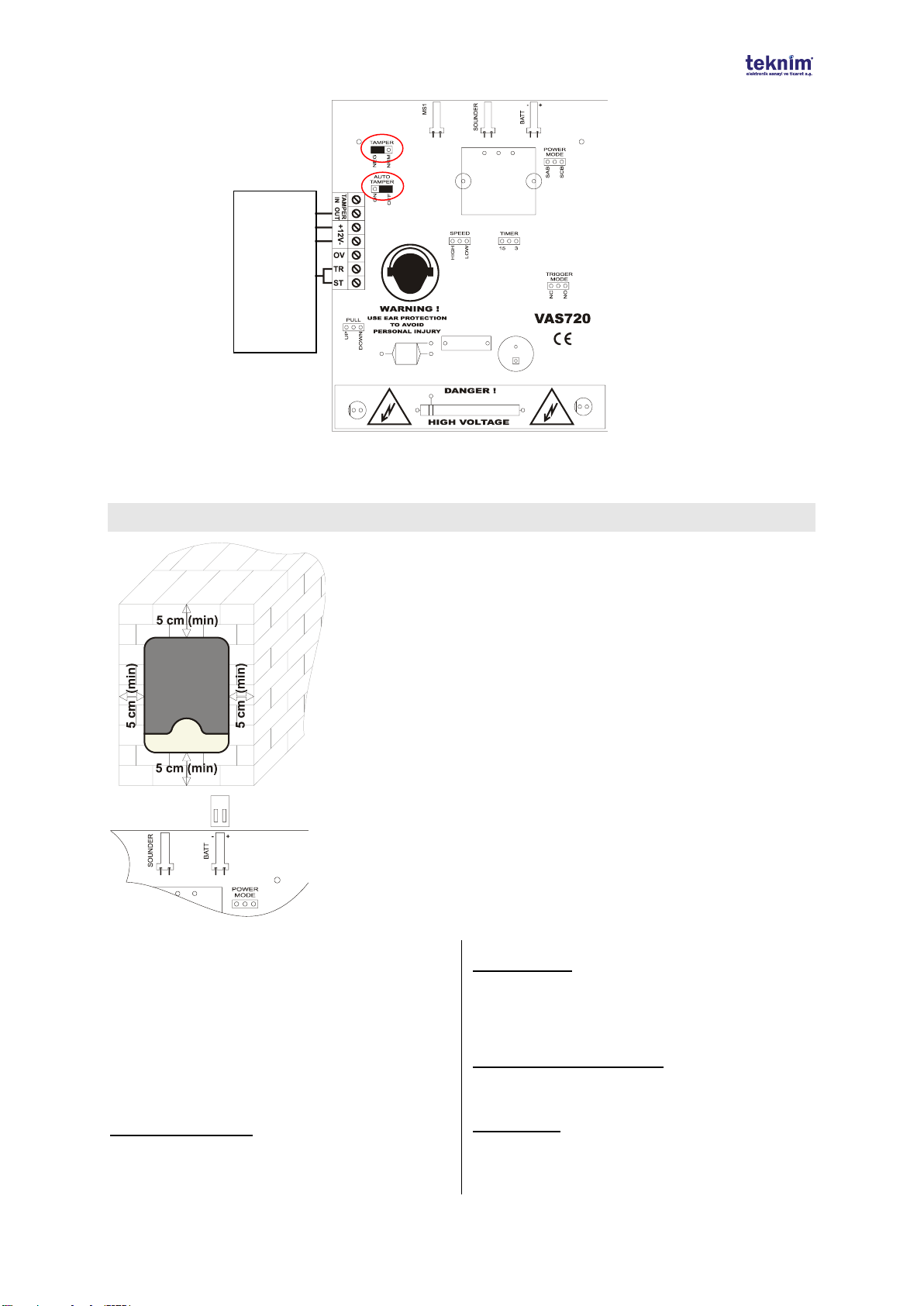
Locate device to the straight place, or else it may
damage device and its environment.
OPERATING CONDITIONS:
Don’t operate device beyond following values.
Temperature : Between -40C and +65C
Humidity : %95 in +40C
POWER SUPPLY:
Use the device only with voltage mentioned in this
manual. If you are not sure about supply voltage you
will use, please contact with your vendor or
manufacturer.
SUPPLY CABLE PROTECTION:
Protect the supply cable against crushing and
breaking.
SERVICE:
Do not attempt to service this unit yourself as there is
no user serviceable part inside. To prevent electric
shock, do not remove covers. In case of breakdown,
contact with your vendor or manufacturer. Refer all
servicing to qualified personnel.
CONDITIONS NEED SERVICE:
Contact with your vendor on the following conditions.
If the device is dropped or the device’s cover is
damaged,
If you realize that, device doesn’t operate properly,
If the device doesn’t operate as mentioned in
operating guide,
If the device isn’t operated in operating conditions,
SPARE PART:
If maintenance includes changing, ensure that
technician uses original parts against electrical shock,
fire, etc.
SECURITY CONTROL:
To control if your device operates in healthy and
convenient conditions, demand service from your
vendor.
SAFETY CHECK
To make sure if your device is working properly and in
safe conditions or not demand service from your dealer
to check device functionality.
TRANSPORTATION
Device must be carefully transported avoiding all
physical bump, stroke and possible fluid entry.
Malfunctions caused by improper transportation.
HUMAN AND NATURE CONDITION
This device contains no chemical or biological
elements that could harm human condition.
FEATURES
High / Low speed sounder option,
Adjustable cutoff Timer (3 / 15 minutes),
SAB / SCB operating mode,
Strobe & Siren can be triggered in NC or NO
mode,
Strobe Unit
Includes rechargeable Ni-MH battery,
Dual action micro switch against sabotage,
Metal cover against impact,
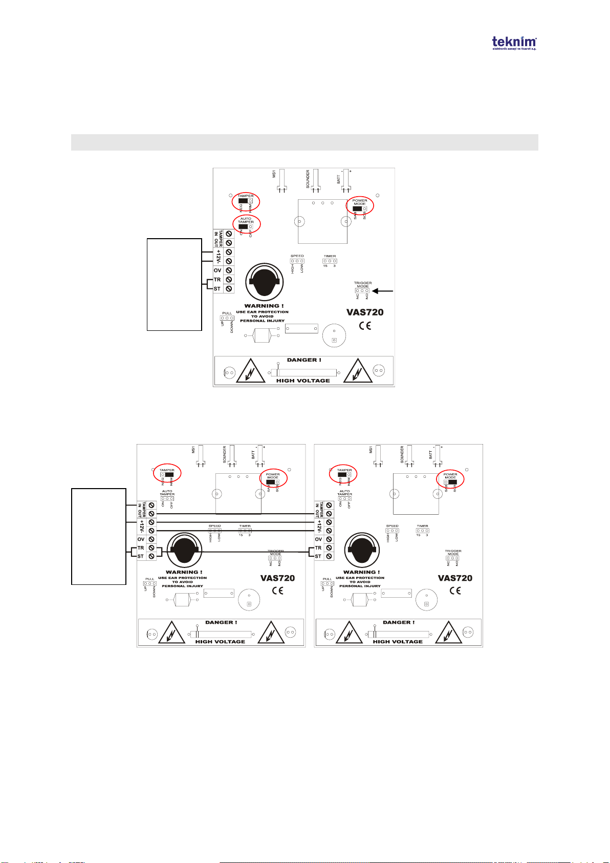
OPERATING
To operate device, apply supply voltage and connect battery. At this time 2 LED become on and off
sequentially to inform you that siren is ready. Also the battery charges in standby mode.
In standby mode if supply voltage cut, the device perceive this as sabotage and starts alarm
immediately. At this moment device is supplied by the battery. This situation continues until the end of
cut off time or existence of the supply voltage.
If siren is triggered in standby mode, siren alarms. At this time if the switch is in SAB mode, siren
current is supplied by alarm panel. If the switch is in SCB mode, siren current is supplied by siren
battery. Siren continues alarm until remove of triggering or the end of cut off time.
Rev.No:03 Rev Date: 11/12/2014 2/4
FIRST MOUNTING SYSTEM
In first mounting there is a system to prevent disturbing technician and other people by alarming. After
the mechanical mounting and before applying supply voltage to siren, connect battery. Normally siren
alarms if supply voltage doesn’t applied. But this doesn’t work for only one time at this moment. And
then when the supply voltage applied, device becomes normal.
CABLE CONNECTIONS
Example 1: Minimum siren connections
Example 2: 5 wire connection with sabotage alarm of 2 sirens
Note: By configuring one of sirens working on SAB mode and the other on SCB mode you prevent sirens to
consume so much current. Look at picture carefully.
Look at TRIGGERING
OPTIONS
0V
+12V Supply
Voltage
Triggering
Alarm Panel
12V Supply
Voltage
Triggering
Alarm Panel
Rev.No:03 Rev Date: 11/12/2014 3/4
Example 4: Connection with VAP Series Panel
Note: If siren output is set as NC in VAP panels, Trigger mode on siren should be set as NC.
MOUNTING INSTRUCTIONS
Mount the device to places that won’t be exposed to direct sun light and rain.
Also give importance to mount the device on a place which it is seen easily
but cannot be reached easily.
Point the mounting holes and cable-in-hole by using siren back plaque or the
template on its cartoon box and then drill holes by using 8mm tip. By using
longer drill tip than the thickness of the wall, drill the wall as the cable pass
through the wall. Mount the siren by using the given screws and suitable
screwdriver. Pass the cables through the hole on the body. Don’t forget to
secrew metal cover to device.
!!! WARNING !!!: Keep each side of siren away from the wall min. 5 cm while
mounting.
!!! WARNING !!!
Connect battery to its plug as shown (Red cable (+), Black cable (-)).
J3 POWER MODE
SAB position: Siren supply voltage is provided by
panel normally. If supply voltage connection cut
between panel and siren, supply voltage of siren is
provided by battery.
SCB position: Siren supply voltage is provided by its
battery in all conditions. At this time current
consumption and so siren loudness become lower.
This jumper’s factory default position is SAB.
CONFIGURATIONS and SETTINGS
J13 - AUTO TAMPER:
Sabotage switch on siren triggers siren automatically.
But to do this, tamper switch should be on "NEG"
position. Factory default value is "OFF"
J12 - TAMPER:
Tamper output could be done with 2 wire connection
(NRM) or 1 wire connection (NEG) in NEG position.
"OUT" should be used as Tamper output (IN is in
GND). Factory Default value is "NRM" (2 wire
connection)
J11 - CUTOFF TIME (TIMER):
This option provides choosing how much time the
sounder works during alarm. Factory default value is
3 minutes.
J10 - SPEED:
By using this switch, siren speed can be increased two
times. Factopry default value is "HIGH".
Tamper Zone
12V Supply
Voltage
SRN Output
VAP Panel
Rev.No:03 Rev Date: 11/12/2014 4/4
TRIGGERING OPTIONS:
Siren and Strobe can be triggered NC or NO. If NC is
selected siren/strobe is triggered when 0V cut. If NO is
selected, siren/strobe is triggered when 0V applied.
Alarm On
TRIGGER
(J9)
PULL
(J14)
If 12V is disconnected
NC
DOWN
If 0V is disconnected
NC
UP
If 12V is connected
NO
DOWN
If 0V is connected (*)
NO
UP
*Factory default
MAINTENANCE ON YOUR OWN
Do not try to fix the device on your own, Removal of
cover may end up with electricity shock.
In case of any defect or malfunction, contact with your
dealer or with authorized service. All the technical
interventions has to be done by technicians of service
company. Device must be cleaned up with a dry fabric.
No-chemicals are allowed for cleaning.
TECHNICAL SPECIFICATIONS
Value
Sound loudness (@1 m)
118 dB max.
Supply Voltage
Min
9 V DC
Max
16 V DC
Current Consumption (@12 V)
Siren
In SAB mode
200 mA
In SCB mode
25 mA
Strobe
100 mA
Standby
25 mA
Strobe frequency (@12 V)
1 Hz
Operating Temperature Range
Between -40C and +65C
Max Humidity
%95 in +40C
Dimensions (W x L x H)
215 x 300 x 60 mm
Weight / (Packaged)
1195 gr / (1352 gr)
MANUFACTURER
Bilgi Elektronik A.Ş.
Address :
Dudullu Organize Sanayi Bölgesi 1. Cadde İsmet Tarman İş Merkezi No:1 Kat:2
No:32 Ümraniye/İstanbul
Tel: +90 216 455 88 46 Fax: +90 216 455 99 06
www.bilgielektronik.com.tr
Sales: [email protected]
Technical Support: [email protected]

Other Teknim Safety Equipment manuals

Teknim TFB-1166 User manual

Teknim

Teknim TFB-1166 User manual

Teknim TWB-1866 Instruction Manual

Teknim

Teknim TWB-1866 Instruction Manual

Teknim TFM-1990 User manual

Teknim

Teknim TFM-1990 User manual

Popular Safety Equipment manuals by other brands

MILLA EURMASK PANAREA quick start guide

MILLA

MILLA EURMASK PANAREA quick start guide

Mueller SENTRYX SUPER CENTURION installation instructions

Mueller

Mueller SENTRYX SUPER CENTURION installation instructions

OCENCO M-20.2 Instructor's manual

OCENCO

OCENCO M-20.2 Instructor's manual

RIB NO TOUCH 868 manual

RIB

RIB NO TOUCH 868 manual

Tractel stopfor B Operating and maintenance instructions

Tractel

Tractel stopfor B Operating and maintenance instructions

ClimbTech BWA030N manual

ClimbTech

ClimbTech BWA030N manual

DICA LiftGuard LG-6-3-90 manual

DICA

DICA LiftGuard LG-6-3-90 manual

Valmont Industries INGAL CIVIL SoftStop product manual

Valmont Industries

Valmont Industries INGAL CIVIL SoftStop product manual

Petzl SHUNT TECHNICAL NOTICE

Petzl

Petzl SHUNT TECHNICAL NOTICE

STI STI-7534 quick start guide

STI

STI STI-7534 quick start guide

DeWalt DXFP841001 instruction manual

DeWalt

DeWalt DXFP841001 instruction manual

Safety Engineering SELF BELAY Operation manual

Safety Engineering

Safety Engineering SELF BELAY Operation manual

Honeywell EBI XLS MASS NOTIFICATION SYSTEM Configuration, Preset Setup, Operation

Honeywell

Honeywell EBI XLS MASS NOTIFICATION SYSTEM Configuration, Preset Setup, Operation

babcockdavis BSRCAY Installation, operation and maintenance manual

babcockdavis

babcockdavis BSRCAY Installation, operation and maintenance manual

SKYLOTEC ERGOGRIP SK 12 Instructions for use

SKYLOTEC

SKYLOTEC ERGOGRIP SK 12 Instructions for use

Tractel Davimast Installation, operating and maintenance manual

Tractel

Tractel Davimast Installation, operating and maintenance manual

Dräger Oxy 3000/3000 MK II Trainer Instructions for use

Dräger

Dräger Oxy 3000/3000 MK II Trainer Instructions for use

3M PROTECTA 8008005 User instruction manual

3M

3M PROTECTA 8008005 User instruction manual

manuals.online logo
manuals.online logoBrands
  • About & Mission
  • Contact us
  • Privacy Policy
  • Terms and Conditions

Copyright 2025 Manuals.Online. All Rights Reserved.