SKF CMDT 391 User manual

User manual
SKF QuickCollect Sensor
CMDT 391 / CMDT 391-Ex
User Manual Part No. 15V-090-00090-100
Revision B –March 2020
WARNING! Read this manual before using the product. Failure to follow the
instructions and safety precautions in this manual can result in serious injury, damage
to the product or incorrect readings. Keep this manual in a safe location for future
reference.

® SKF is a registered trademark of the SKF Group.
Android is a trademark of Google LLC.
The Bluetooth® word mark and logos are registered trademarks owned by Bluetooth SIG, Inc. and any use of
such marks by SKF is under license.
ICP® is the registered trademark of PCB Group.
iOS is a trademark or registered trademark of Cisco in the US and other countries.
All other trademarks and trade names are the property of their respective owners.
© SKF Group 2019
The content of this publication is the copyright of the publisher and may not be reproduced (even in extract
form) unless prior written permission is granted. Every care has been taken to ensure the accuracy of the
information contained in this publication, but no liability can be accepted for any loss or damage whether
direct, indirect or consequential arising from the use of the information contained herein.
Product Support –Contact Information
Product Support –To request a Return Authorisation, Product Calibration or Product Support Plan, use the
web page links for direct contact and support.
Product Sales –For customer support or information on purchasing condition monitoring products, contact
your local SKF sales office.
General Product Information
For general product information (i.e. product data sheets, accessories catalogue, etc.), visit the Condition
Monitoring Systems page at SKF.com and select the appropriate product link.
Technical Support Group
For technical support when troubleshooting product installation or product performance, etc., use our
technical support web page to search the knowledgebase, find further product information or contact one
of our Technical Support Groups.
201703FP/PW-Feb-2020

QuickCollect CMDT 391 / CMDT 391-Ex TOC - 1
User Manual –Revision B
Table of Contents
Introduction 1-1
Safety Messages 1-1
Specific Conditions of Use 1-2
About This Manual 1-2
Technical Support 1-3
SKF QuickCollect Sensor 2-1
SKF QuickCollect Sensor System Overview 2-1
Sensor Controls and Indications 2-3
Vibration and Temperature Measurements 2-4
Calibration, Repair and Disposal 2-7
Using the QuickCollect Sensor 3-1
Preparing the Sensor for Use 3-1
Measurement Guidelines 3-2
Using the QuickCollect or ProCollect Apps 4-1
ProCollect App 4-1
Downloading, Installing and Launching the QuickCollect App 4-1
Preparing to Take Measurements 4-2
Taking Measurements 4-7
Over-the-Air Firmware Updates (OTA) 4-10
Viewing Graphical Measurement Results 4-14
Reporting Measurement Results 4-16
Index i i-1


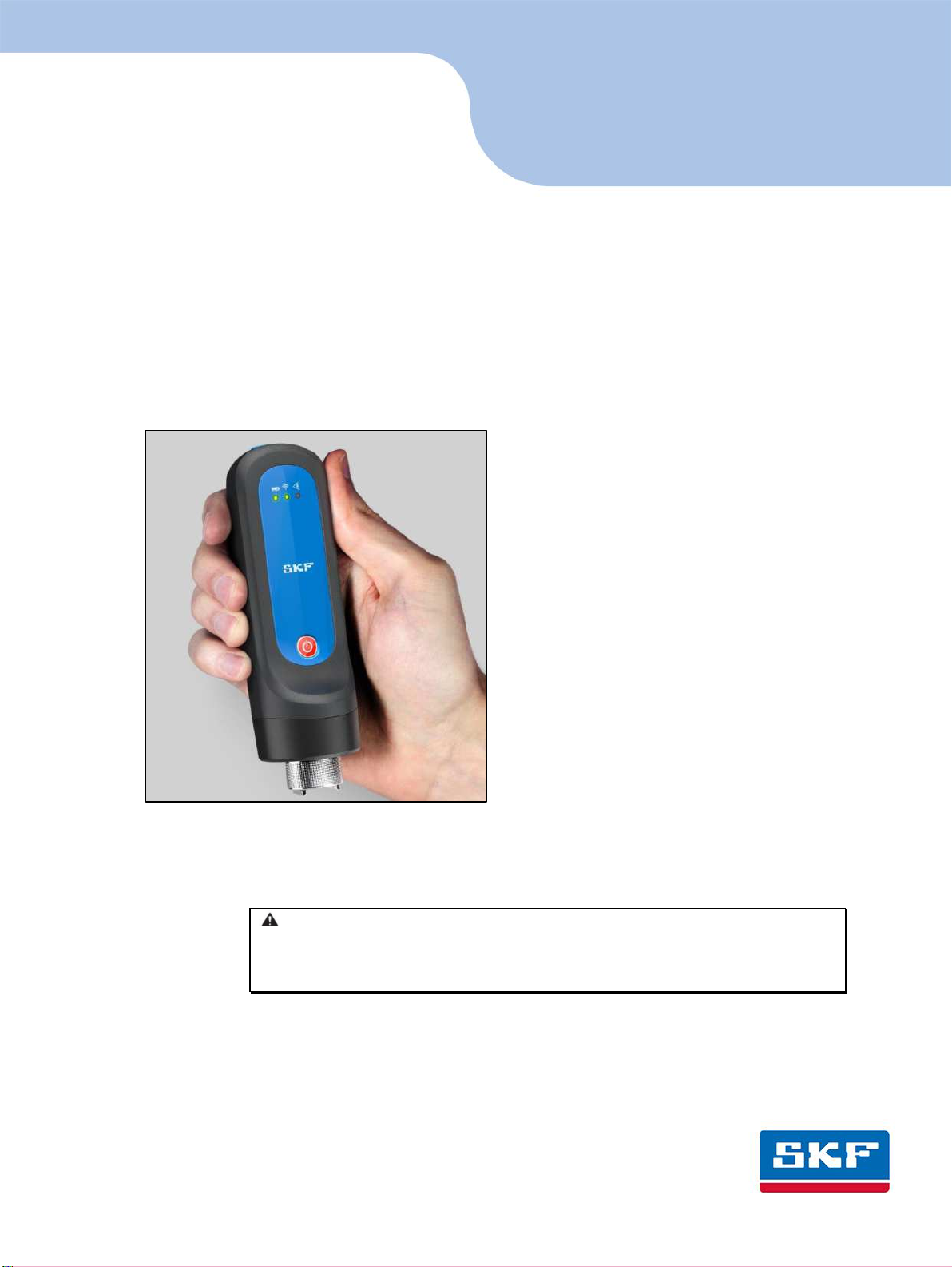
QuickCollect CMDT 391 / CMDT 391-Ex 1 - 1
User Manual –Revision B
1
Introduction
Safety Messages
WARNING! Your safety is extremely important. Read and follow all warnings in
this document before handling and operating the equipment. Failure to observe
the safety warnings may result in personal injury and/or damage to the
equipment and data loss.
WARNING! - Warning messages are used to highlight an operating procedure, practice,
condition or statement that must be strictly observed to prevent equipment damage or
destruction, or corruption to or loss of data.
IMPORTANT: Important messages means that there is a risk of product or property
damage if the instruction is not heeded.
Personnel Safety
Dress properly. Do not wear loose clothing or jewellery. Keep hair, clothing and gloves
away from moving parts.
Do not overreach, always maintain proper footing and balance when placing or
retrieving the sensor.
Use safety equipment. Always wear eye protection. Non-slip safety shoes, hard hat and
hearing protection must be used in the appropriate settings.
Do not repair or adjust energised equipment alone, under any circumstances. Someone
capable of providing first aid must always be present for your safety.
Persons working on or near high-voltage equipment should be familiar with approved
industrial first-aid methods.
Never open or work on energised electrical systems unless authorised by a responsible
authority. Energised electrical systems are dangerous and electric shocks from energised
systems can be fatal. Always ensure that the necessary permission or permit to work has
been obtained before commencing any work.
Always obtain first aid or medical attention immediately after sustaining an injury. Never
neglect an injury, no matter how superficial it initially seems.
Device Safety
If the sensor has been dropped, check for damage before using. Sensors must only be
serviced by qualified SKF repair personnel.
Use only accessories recommended or provided by SKF or the manufacturer. The
magnet must only be attached by hand, no mechanical advantage is to be used. Be
aware that the use of excessive torque when attaching the magnet can damage the
sensor. The recommended torque is 2.9 Nm.

1 - 2 QuickCollect CMDT 391 / CMDT 391-Ex
User Manual –Revision B
No Submersion/Immersion
The sensor is dust tight and has an IP rating consistent with resisting water spray from all
directions. If it is subjected to more extreme conditions, this may affect its operation.
Avoiding Damage and Injury
To avoid damage to the sensor or injury caused by the sensor falling, always place it on a
solid stable surface when not in use and do not place any heavy objects on it.
Use a damp, clean cloth for general cleaning. Unless explicitly stated otherwise do not
use cleaning fluids, abrasives or aerosols as these might cause damage, fire or electrical
shock.
Specific Conditions of Use
The Ex approved version of the QuickCollect sensor, CMDT 391-Ex, must be used in
accordance with the safety instructions provided with that device.
Agency approvals for the CMDT 391-Ex with CMAC 8010-Ex cable:
Ex ib IIC T4 Gb –20 °C ≤Ta ≤+60 °C
Ex ib IIC T4 Gb – °C ≤ Ta ≤ +60 °C
Class I, Zone 1, AEx ib IIC T4 Gb – °C ≤ Ta ≤ + °C
IS Class I, Div. 2, Group A, B, C, D, T4
About This Manual
This manual provides information on the setup and use of the SKF QuickCollect Sensor
Bluetooth® instruments (part no. CMDT 391 and CMDT 391-Ex) and the SKF QuickCollect
app. In this manual, the sensor instrument is commonly referred to as the QuickCollect
sensor, or just the sensor and the companion app as SKF QuickCollect app or just the
app.
The features and functions are described from the perspective of a CMDT 391 but apply
equally to the CMDT 391-Ex provided that the safety instructions are followed.

QuickCollect CMDT 391 / CMDT 391-Ex 1 - 3
User Manual –Revision B
In this manual certain conventions are used:
Bold type is used to indicate text that appears in a menu, window or dialogue
box.
Italics are used to emphasise important information.
➢is used to indicate notes to the reader.
Step-by-step procedures are sequenced using bullet points, •.
Technical Support
For any questions regarding the installation or operation of SKF products, before
contacting the help desk, please visit the self-help portal to see if the answer has already
been published:
Technical Support Self-help Portal: www.skf.com/cm/tsg
If further assistance is needed, please submit a support request by clicking on the
SUPPORT tab, and one of our support engineers will be in contact.
The technical support team can be reached during normal business hours (7 am to 4 pm
local time) by phone, e-mail or live chat:
Customers in Europe, Middle East and Africa:
Phone: +46 31 337 6500
E-Mail: TSG-EM[email protected]m
Chat: www.skf.com/cm/tsg
Customers in all other locations:
Phone: 1-858-496-3627 or toll-free (USA) 1-800-523-7514
E-Mail: TSG-Americas@skf.com
Chat: www.skf.com/cm/tsg


QuickCollect CMDT 391 / CMDT 391-Ex 2 - 1
User Manual –Revision B
2
SKF QuickCollect Sensor
SKF QuickCollect Sensor System Overview
The SKF QuickCollect sensor is part of the SKF Enlight QuickCollect system, which also
includes SKF mobile apps and SKF Machine Health software. This system is used by
service, reliability, operations or maintenance personnel as part of a walk-around data
collection program. With one wireless vibration and temperature sensor which can be
connected to a tablet, smart phone or smart watch, the user can monitor hundreds of
assets per day and thousands of assets per month. The data can be analysed on the spot
in real time or sent to the cloud for analysis.
Figure 2 - 1.
On the job with an Enlight QuickCollect system.
In brief, a typical operation would include the following steps:
Take the QuickCollect sensor and smart device out to the rotating machinery to be
monitored (such as a pump or motor).
Mount the sensor on the bearing housing using the magnetic mount.
Initiate the sensor measurement wirelessly using Bluetooth®Low Energy from the
SKF QuickCollect, DataCollect or ProCollect app running on a smart device.
After making the measurement, remove the sensor and proceed to the next
machine or measurement location and continue taking measurements.
When complete, return the sensor to its charger.

2 - 2 QuickCollect CMDT 391 / CMDT 391-Ex
User Manual –Revision B
Figure 2 - 2.
A portable data collection system.
The QuickCollect sensor uses Bluetooth® low-energy version 4.2 wireless technology to
communicate with off-the-shelf iOS and Android devices using the SKF QuickCollect,
DataCollect or ProCollect applications for capturing overall machine vibration (velocity
and enveloped acceleration), time waveform and temperature data.
The QuickCollect sensor features wireless data transfer, a rugged design and a
rechargeable battery. The sensor increases operator safety by eliminating the hazards
and inconvenience of cumbersome cables to provide a safe, fast and easy-to-use system
for performing front-line machinery condition monitoring. The data collected and
transferred to the SKF app is displayed on the screen with easy-to-identify colour-coded
bars that indicate alarm status: green for acceptable, yellow for alert and red for danger.
Full specifications for the sensor are listed in its product datasheet.
Figure 2 - 3.
QuickCollect sensors CMDT 391 and CMDT 391-Ex.

QuickCollect CMDT 391 / CMDT 391-Ex 2 - 3
User Manual –Revision B
Figure 2 - 4.
The SKF QuickCollect app for mobile devices.
Sensor Controls and Indications
Figure 2 - 5.
Sensor controls and LEDs.
Power button
Battery LED
Communication LED
All-purpose check LED
Power button –Powers the sensor on and off. When the sensor is off, pressing the
power button will immediately turn on the sensor.

2 - 4 QuickCollect CMDT 391 / CMDT 391-Ex
User Manual –Revision B
When powered on, a 15-minute inactivity timer will start. If no communication is
detected between the sensor and QuickCollect, DataCollect or ProCollect within 15
minutes, the sensor will automatically power off.
When powered on, a button press of less than 3 seconds will reset the inactivity timer.
When powered on, a press and hold of greater than 3 seconds will power off the sensor.
Battery LED –(Green, Red)
When connected to a (powered) charger:
Green –Indicates battery had reached full charge, charging has
stopped.
Red, solid –Indicates battery is being charged.
Otherwise, the battery LED is normally off but:
Red, slow blinking –Indicates low battery. Remaining life is about 15%
of fully charged level.
Red, fast blinking –Indicates battery charge is too low to keep the
sensor powered on; the device will power itself off.
Communication LED –(Green, Red)
Off –Indicates the sensor is powered off.
Green, blinking –Indicates the sensor is powered on and not connected to the
app.
Green, solid –Indicates the sensor is powered on and connected to the app.
Toggling between green and red –Firmware update in progress.
All-purpose check LED –(Green, Red, Amber)
Green –No errors
Red, solid –Indicates an error condition: factory state, no serial number,
uncalibrated.
Red, fast blinking –Indicates a critical error.
Toggling between red and amber –Indicates an external sensor error.
Vibration and Temperature Measurements
When used directly on a machine, the QuickCollect sensor can collect simultaneous
vibration and temperature measurements. Note that when an external sensor is being
used (external sensor cable connected), a temperature measurement cannot be made.
Vibration
Most machinery problems result in excessive vibration. Mechanical looseness,
imbalance, soft foot (foundation), misalignment, shaft bow, bearing wear, gear defects,
or rotor damage can all be detected using vibration measurements.
When performing measurements, the sensors iratio output is processed to produce
two very meaningful vibration measurements for each measurement point.

QuickCollect CMDT 391 / CMDT 391-Ex 2 - 5
User Manual –Revision B
Velocity –Viratio eloit is osidered the geeral purpose iratio
measurement for detecting machinery problems. This is because most machinery
problems generate low to mid-frequency sinusoidal-type vibration signals (problems
such as imbalance, misalignment, bent shaft and looseness), and velocity
measurements focus on detecting vibration signals occurring in this frequency
range. ISO standards provide general guidelines for vibration severity using velocity
criteria.
Enveloped acceleration –Rolling element bearing faults cause low-amplitude
impulsive -type vibration signals at a regular rate of repetition. When monitored
using velocity measurements, these low-energy impulsive signals are typically lost in
surrounding machinery vibration noise caused by imbalance, misalignment,
looseness, etc. Enveloped acceleration measurements filter out surrounding
machine vibration noise and enhance the impulsive nature of repetitive rolling
element bearing or gear fault vibration signals, allowing much earlier and accurate
bearing fault detection. Not used for overall machine vibration monitoring,
enveloped acceleration measurements ensure consistent early detection of bearing
and gear-type defects.
Measurement and analysis capabilities –When the sensor is used in conjunction
with the SKF ProCollect app and SKF Enlight Centre the available sample rates
(bandwidth) and FFT resolution are extended and adjustable.
QuickCollect Sensor - Temperature
Temperature measurement is a useful indicator of mechanical condition or the load
applied to a specific component. As a bearing or its lubrication fails, friction causes its
temperature to rise. Measuring temperature changes at the bearing helps the early
recognition of problems and the scheduling of corrective maintenance before a serious
and expensive failure occurs.
The sensors opening for taking temperature measurements is located next to the
magnet mounting, Figure 2 –6 below. The infrared (IR) sensor has a range of 4 cm and
quickly determines the temperature of the equipment to which the QuickCollect sensor
has been attached. Note that the temperature measurement is unavailable when the
external sensor cable is in use.
Figure 2 - 6.
IR sensor location.

2 - 6 QuickCollect CMDT 391 / CMDT 391-Ex
User Manual –Revision B
External Sensor Setup (not compatible with the CMDT 390 sensor)
The CMDT 9 has ee egieered to support a to-wire, constant current powered,
external accelerometer that provides an output of 100 mV/g and a bias voltage to
indicate sensor OK.
For the connection to the CMDT 391, the correct SKF cable (part no. CMAC 8010) must
be used, Figure 2 –7 below. This ale has a -pi oetor that ates ith the uits
external sensor/charging connector, Figure 3 - 1.
Figure 2 - 7.
CMAC 8010 –External sensor cable for the CMDT 391.
Important: Note that the CMDT 391-Ex uses cable part number CMAC 8010-Ex.
Refer to the safety instructions for specific conditions of use and the
entity/connector parameters to be considered when selecting a suitable Ex
approved external accelerometer.
The SKF recommended external accelerometer for use with the CMDT 391 is the
CMSS 2100 and for the CMDT 391-Ex it is the CMSS 786A-IS.
Ensure the external sensor cable is securely attached by following these steps:
•Loate the sall oth o the QuikCollet oetor.
•Align the cable connector's keyway to that notch and press gently to join the
two connectors.
•Tighten the screw lock on the cable mounted connector to secure it (do not
over tighten).
Or alternatively:
•Press the two connectors gently together and slowly rotate one connector until
the keyway slides into the notch, and then tighten the screw lock to secure.
The maximum total external ale legth the CMDT 9 a drie, is etres. The
CMAC 8010 cable is 2-metres long so the maximum length of additional external cable is
8-etres.
The other end of the external sensor cable has a 2-pin (MIL-C-5015) connector suitable
for direct connection to standard SKF accelerometers. If the cable is to be attached to
another type of connector then a suitable adapter must be sourced.

QuickCollect CMDT 391 / CMDT 391-Ex 2 - 7
User Manual –Revision B
Note the following:
•It is not possible to take a measurement using the internal sensor whilst a cable
is attached to this connector, as the internal sensor is disconnected and
therefore inoperable. This applies even if no external sensor is attached to that
cable.
•When using an external sensor cable the temperature measurement is similarly
unavailable.
•Battery life will be reduced as the QuickCollect sensor is powering the external
sensor.
•Never carry the QuickCollect sensor by the attached cable.
The following status conditions may apply when using an external sensor/cable
combination:
1. No cable plugged in - this is the expected status when using the internal sensor
to acquire data and not having any sort of cable attached.
2. Cale plugged i ad o error deteted - this is the expected status when using
an external sensor to acquire data. It indicates the external sensor cable is
attached and no error condition detected.
3. Cable plugged in and a short circuit error detected.
4. Cable plugged in and an open circuit error detected.
5. Cable plugged in, but no sensor attached.
Notes:
Status conditions 3, 4 and are osidered error oditios ad are sigalled the All-
purpose check LED flashing alternate amber and red, approximately 2 times a second
It is not possible to take a measurement when an error condition is detected.
At present, it is not possible to distinguish between the open circuit error condition (4)
ad the o sesor attahed oditio .
Calibration, Repair and Disposal
It is recommended that the QuickCollect sensor be calibrated every 24 months, with the
first calibration due 24 months from the first date of in-service, use.
SKF can provide calibration and if needed repair/replacement of QuickCollect sensors.
Electrical waste and electrical equipment should be recycled as specified by the WEEE-
directive and not be placed in the general refuse. Product should be sent to an approved
recycling centre for safe recycling, recovery, reuse or returned to SKF.


QuickCollect CMDT 391 / CMDT 391-Ex 3 - 1
User Manual –Revision B
3
Using the QuickCollect Sensor
Preparing the Sensor for Use
Charging the Battery
The battery should only be charged in an office environment. Always use the
correct charger: for the CMDT 391 this is the CMAC 8004 and for the CMDT 391-Ex
this is the CMAC 8007.
The sensor is equipped with an internal lithium ion battery. Prior to using the sensor for
the first time, use the provided power supply to fully charge the sensor battery.
The sesors ol eteral oetor is the -pi ak oetor. This is dual use: for
charging the sensor (when not collecting data) and for using an external accelerometer
to take vibration measurements.
Figure 3 –1.
External sensor and charging connector.
To charge the battery:
Connect the charger to an AC outlet (if necessary, use regional AC outlet adapters).
Align, connect and tighten the chargers ale to the sesors eteral -pin
connector.
The battery LED will be red whilst the battery is charging. The battery will be fully
charged after approximately four hours. The battery LED will be green when the
battery is fully charged.
Once the battery is fully charged, the sensor is ready for operation. The battery LED will
blink red when the power level is low. If the battery level becomes too low, the sensor
will automatically power itself off to prevent battery damage.
➢When not being used for data collection, connect the sensor to its
charger.

3 - 2 QuickCollect CMDT 391 / CMDT 391-Ex
User Manual –Revision B
Measurement Guidelines
Performing Vibration Measurements
Vibrations measurements are typically performed with the machine operating under
normal conditions. For example, when the machinery has reached its normal operating
temperature and is running under its normal rated condition (at rated voltage, flow,
pressure and load). For machines with varying speeds or loads, perform measurements
at all extreme rating conditions, as well as at selected conditions within these limits.
Plae the sesors aget o the ahies easureet poit. When placing the
sensor on the machine, generally avoid greasy, oily or wet surfaces, housing joints,
panels and non-structural parts. Select the best measurement point (specifically avoid
unloaded bearing zones) and be consistent in terms of sensor position, sensor
angle/alignment and contact pressure.
If possile, hoose a flat surfae i the earigs load zoe. Measureets should e
taken at the same precise location (as moving the probe only a few inches can produce
drastically different vibration readings). To ensure measurements are taken repeatably,
mark the measurement point with a permanent marker.
Proper hand-held sensor technique is vital to the accuracy of measurements. It is critical
that consistent measurements are made.
When taking measurements using an external cable and sensor, care must be taken not
to move the cable during data collection.
Using the cable in conjunction with different external accelerometers may give different
readings due to the variation in the accelerometers used. Measurements will also vary
between the internal sensor and an external sensor. Be consistent by always using the
same sensor for a particular measurement point, i.e. internal sensor or same external
sensor.
Performing Infrared Temperature Measurements
To perform accurate non-contact infrared temperature measurements, bear in mind
infrared sensor cleanliness. The infrared sensor has a small opening. Dirt, grease or oil
may enter the opening and cause inaccurate temperature measurements. If necessary,
clean the opening using alcohol and cotton buds.

QuickCollect CMDT 391 / CMDT 391-Ex 4 - 1
User Manual –Revision B
4
Using the QuickCollect or ProCollect Apps
ProCollect App
The QuickCollect sensor can be used with the SKF QuickCollect, DataCollect or ProCollect
apps. The operation of the QuickCollect app is described below, for details and guidance
regarding the use of the ProCollect app, refer to the SKF ProCollect User Manual (15V-
090-00089-100).
Downloading, Installing and Launching the QuickCollect App
The QuickCollect app is compatible with iOS 9.0 or later and can be downloaded from
the Apple App Store or Google Play.
To launch QuickCollect for the first time:
•Tap the SKF QuickCollect icon on the device. The welcome screen will appear.
Figure 4 –1.
QuickCollect app welcome screen.
•Tap Configure thresholds to jump directly to the Settings table and configure the
measurement danger and alert alarm thresholds or tap Skip to aigate to the apps
home screen.
Tap to select Stop reminding me to skip this welcome screen when launching the
app in the future.

4 - 2 QuickCollect CMDT 391 / CMDT 391-Ex
User Manual –Revision B
Preparing to Take Measurements
To configure alarm thresholds:
•Navigate to the Settings table, either from the welcome screen as described above
or by tapping the settings icon in the top right of the apps hoe sree.
Figure 4 –2.
Navigating to the Settings table from the home screen.
•Tap the QR icon to sa a ahies QR ode i order to autoatiall ollet
information and values for thresholds for the machine.
OR
•Tap within the MACHINE ID text box to bring up a keyboard and enter unique
identifying information for the machine (a machine ID or tag reference).
This manual suits for next models
1
Table of contents
Other SKF Accessories manuals