TekTone NC403TS User manual

NC403TS Monitor and NC404TS Master Station Operation and
Installation Manual
Copyright© 2001-2021 TekTone® Sound & Signal Mfg., Inc., All rights reserved.
No part of this publication may be copied without the express written permission of TekTone®
Sound & Signal Mfg., Inc. The content of this manual is furnished for informational use only, is sub-
ject to change without notice, and should not be construed as a commitment by TekTone. TekTone
Sound & Signal Mfg., Inc. assumes no responsibility or liability for any errors or inaccuracies that
may appear in this documentation.
TekTone, the TekTone logo, Tek-ALERT, Tek-BRIDGE, Tek-CALL, Tek-CARE, Tek-CHECK-IN,
Tek-COM, Tek-ENTRY, Tek-GUARD, Tek-MICRO, Tek-MMARS, Tek-PAGING, Tek-SAFE and
Tek-STATUS are either registered trademarks or trademarks of TekTone® Sound & Signal Mfg., Inc.
in the United States and/or other countries. All other trademarks are the property of their respective
owners.
TekTone® Sound and Signal Mfg., Inc., 324 Industrial Park Road, Franklin, North Carolina 28734,
USA.

Table of Contents
Introduction 4
Installing the NC403TS Monitor and NC404TS Master Station 5
Configuring the NC403TS Monitor and NC404TS Master Station 8
Calls Screen 11
Answering and Placing Calls on Master Stations 13
Password Protection 13
Time Screen 14
Changing the Time 14
Settings Screen 15
Changing the Volume 15
Status Screen 16
Dial Screen 17
Menu Screen 20
Using the NC404L Sidecar Master 21

Introduction
Introduction
The NC403TSMonitor and NC404TS Master Station are both purpose-built to be proprietary LCD
touchscreen nurse call event monitors and master stations for the Tek-CARE platform, and these devices
run on the facility LAN. For more specific information on these devices, refer to IL1068 Master Station
User Guide. An NC475 Tek-CAREAppliance Server is required for the installation of both devices.
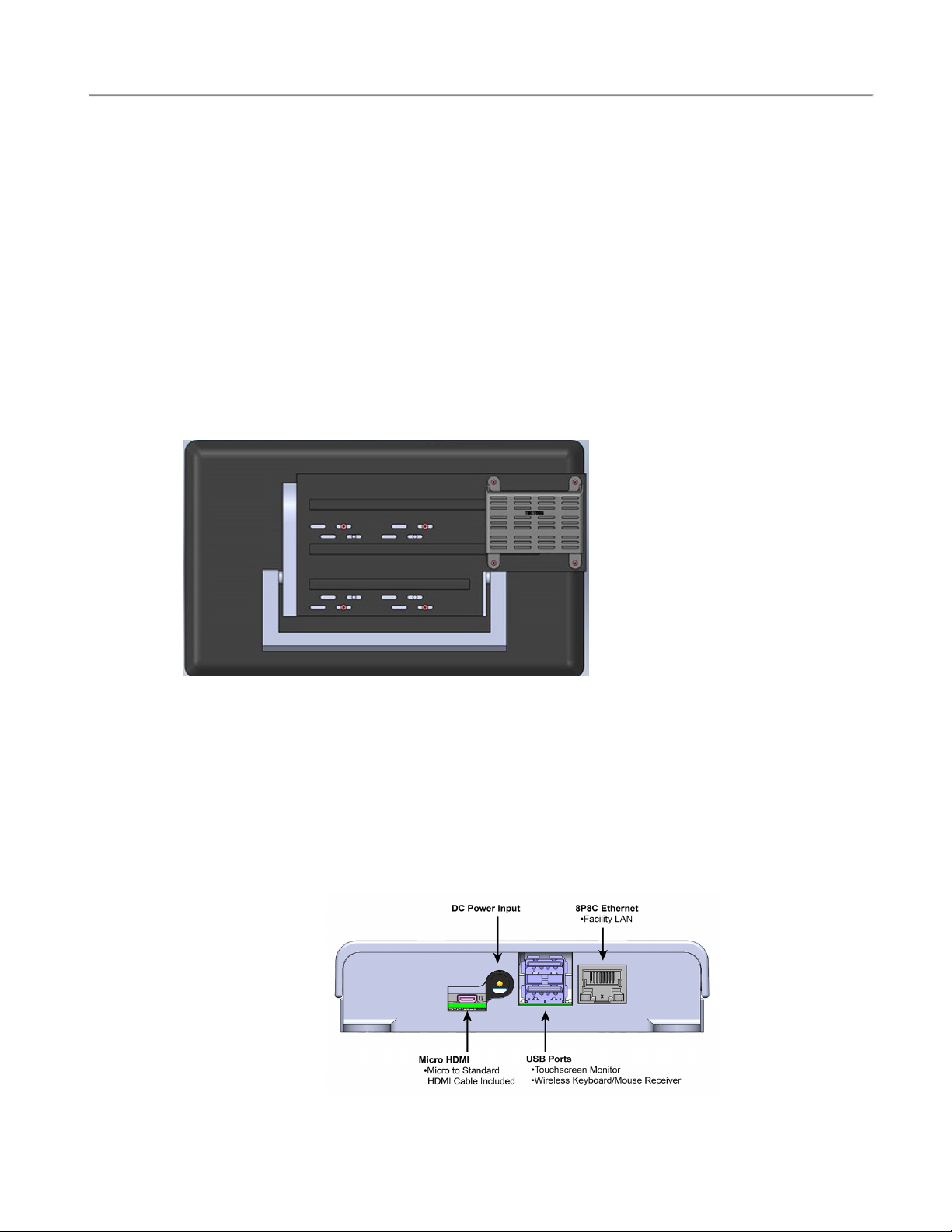
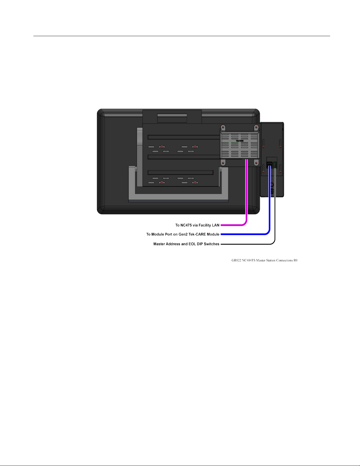
All connections are located at the rear of the both devices, and they are designed to be either desk- or
wall-mounted. A CL234 wall-mount bracket may be purchased separately for the wall-mounted option
for the NC403TS Monitor. The CL234/CL231 is used in conjunction with a TV/Monitor wall-mount
bracket which must be a VESA mount design. A minimum clearance of 1.2" behind the monitor is
required to accommodate the PM593. The TekTone ST316, wireless keyboard and mouse, may be con-
nected to the devices if desired.
In most facilities, both devices will be visible and installed to be accessible by all applicable staff. Calls
are automatically sorted by priority and duration, with the highest priority calls being displayed first. If
the handset for the NC404TS Master Station is lifted to answer a call, the highest priority call is
answered unless another call is manually selected.
The devices must be dedicated to the Tek-CARE system. Do not attempt to install or connect non-
TekTone applications with the Tek-CARE Network unless specifically instructed by TekTone Technical
Support.
NC403TS Monitor Components NC404TS Master Station Components
NC318 - Touchscreen monitor
lUSB cable
lPower cable
NC403NOTS - PM593 controller & case
lCA060 - 18" HDMIto micro HDMI
cable
lHW336 - Four 10mm pan "head" screws
lPK307 - Power Supply
(Optional) CL234 NC403TS Monitor Mounting
Bracket
lHW376 - Four 14mm VESA mounting
screws
NC318 - Touchscreen monitor
lUSB cable
lPower cable
NC403NOTS - PM593 controller & case
lCA060 - 18" HDMIto micro HDMI cable
lHW336 - Four 10mm pan "head" screws
lPK307 - Power Supply
NC404L - Master Station (sidecar)
lTA415LB - Handset
lCA043 - 6' Coiled phone cord
lHW379 - Four 10 X 3/8" Phlps, PH/ZP,
Type B, Self-Tap
CL231 NC404TS Mounting Bracket
lHW376 - Four 14mm VESA mounting
screws
4|IL1052 NC403TS and NC404TS Installation Manual Copyright ©TekTone Sound and Signal Mfg., Inc. All Rights Reserved

Installing the NC403TS Monitor and NC404TS
Master Station
NOTE: The NC475 is required to be installed and running prior to the installation of the
NC403TS Monitor and NC404TS Master Station.
Installing the NC403TS Monitor
Connect and screw in the following:
Screw the NC403NOTS onto the back of the monitor using the four HW336 screws provided. (If using
the CL234 wall-mount bracket, screw the bracket to the NC318 monitor and to the NC403NOTS with
the additional screws provided as shown below.)
On the back of the NC403TS Monitor, connect the following:
1. Connect the PK307 plug-in transformer to the DC Power Input of the NC403NOTS.
2. Connect the USB cable to the USB port on the NC403NOTS and the monitor.
3. Connect the CA060 HDMI cable to the Micro HDMI on the NC403NOTS and the monitor.
4. Connect the NC403NOTS Ethernet jack to the Facility LAN.
5. Connect the monitor's power cord to an AC outlet and then to the NC318 monitor.
NC403NOTS Interconnection Diagram
Copyright ©TekTone Sound and Signal Mfg., Inc. All Rights Reserved IL1052 NC403TS and NC404TS Installation Manual |5
Installing the NC403TS Monitor and NC404TS Master Station

Installing the NC403TS Monitor and NC404TS Master Station
Installing the NC404TS Master Station
Connect and screw in the following:
1. Screw the NC404L to the CL231 bracket with the four HW379 screws.
2. Screw the CL231 bracket to the NC318 monitor with the four HW376 screws provided.
3. Screw the NC403NOTS to the CL231 bracket with the provided four HW336 mounting screws.
Connect the following on the back of the NC404TS Master Station:
1. Connect the PK307 plug-in transformer to the DC Power Input of the NC403NOTS.
2. Connect the USB cable to the USB port on the NC403NOTS and the monitor.
3. Connect the CA060 HDMI cable to the Micro HDMI on the NC403NOTS and the monitor.
4. Connect the NC403NOTS Ethernet jack to the facility LAN.
5. Connect the included coiled cord between the handset and the 4-pin jack on the rear of the
NC404L.
6. Connect the CAT5 cable to the back of the NC404L and to the Gen2 CEmodule.
7. Assign a unique address for each NC404TS Master Station using the DIP switch at the rear of the
NC404L sidecar.
8. Connect the monitor's power cord to an AC outlet and then to the NC318 monitor.
Refer to the NC403TS Interconnection Diagram on the previous page for the various connections to the
device.
6|IL1052 NC403TS and NC404TS Installation Manual Copyright ©TekTone Sound and Signal Mfg., Inc. All Rights Reserved

Next, find the correct network IP address. To find the correct network IP address connected to the Tek-
CARE Network, go to the NC475 Tek-CAREAppliance Server.
NOTE: For more information on setup, updates, and networking, refer to the NC475 Tek-
CAREAppliance Server Installation Manual, IL1012.
Use the arrow keys on the front of the NC475 to scroll to the right. At the Menu screen, scroll down to
Facility IP Setting and scroll down to view the IP address, netmask (if applicable) and gateway (if
applicable).
Note the IP Address assigned to the NC475 Tek-CARE Appliance Server here:
________.________.________.________
Once you have noted the IP address, press the red Exit button to return to the setup menu. Use the arrow
keys to scroll through the Setup menu and select the Exit option. Press the green Okay button. The
NC475 Tek-CAREAppliance Server will reboot and return to the home screen.
Power up the device. Once the NC403TS Monitor or NC404TS Master Station is turned on for the first
time, enter the IP address as noted above in the Connection Settings screen and choose a unique Device
ID between 1 - 254. Below is an example of an IP address and Device ID entered in the Connection Set-
tings screen.
Note the Device IDs of each NC403TS Monitor and NC404TS Master Station installed on the system.
At the bottom of the Connection Settings screen, click Network Setup.
On the Network Setup screen, DHCP will be automatically defaulted. In most instances, the DHCP
option should be chosen.
NOTE: Only use the Static option when directed by facility IT staff. Theywill have to
provide the appropriate address and subnet information to enter into the Static IP address
and Subnet fields.
If changes were made to the Network Setup screen, click Save. This option will apply the changes and
force the NC403TS Monitor and NC404TS Master Station to reboot.
If there were no changes made to the Network Setup screen, click Cancel which takes you back to the
Connection Settings screen. If you wish to reset the connection settings, touch Reset Connection Set-
tings. This will force the device to reboot and change back to the default settings before any changes
were made.
Click Connect to be redirected to the home page of the NC403TS Monitor and NC404TS Master Sta-
tion.
Copyright ©TekTone Sound and Signal Mfg., Inc. All Rights Reserved IL1052 NC403TS and NC404TS Installation Manual |7
Installing the NC403TS Monitor and NC404TS Master Station

Configuring the NC403TS Monitor and NC404TS Master Station
Configuring the NC403TS Monitor and NC404TS
Master Station
Once hardware installation is complete, set up the system configuration. The LS450 Config Tool is used
to configure the system, and is installed on a programming laptop. Once the hardware is installed,
choose Load Configuration from System on the splash screen.
Refer to the LS450 Config Tool Installation and Operating Instruction Manual, IL855, for more inform-
ation on how to set up the Config Tool. The NC403TS Monitor and NC404TSMaster Station settings
can be found in the Masters and Monitors pages of the Config Tool. Go to the Masters page first and
enable the NC404TS Master Station and confirm the type. Apply and save the changes and then go to
the Monitors page. Select an available monitor from the monitor index and click Edit.
Change the name of the monitor to something that is easily recognizable. If this monitor is to be recog-
nized on the Tek-CARE Network, check Exists. If the monitor disconnects from the network and the
facility wants a fault displaying that information, click Supervised.
Under Type, choose Standard for the NC403TS Monitor Paired with NC404 for the NC404TS Master
Station and select the paired master station which was created earlier.
Under Views, choose either List only (same functionality as an event monitor), List and Icon, or List
and Map for the view mode of the devices.
Check Play Sounds if you want the monitor to play sounds when a call is coming in. The NC475 will
serve as the primary annunciator on the system (Monitor ID 0000). However, if it will be unattended in
an equipment room, uncheck Primary Annunciation.
Under Zones and Call Filter, select the applicable zones and call filters that are to be annunciated on
the monitor. Click Apply.
8|IL1052 NC403TS and NC404TS Installation Manual Copyright ©TekTone Sound and Signal Mfg., Inc. All Rights Reserved

The List and Icon view will give an icon layout.
Click Edit next to Icon Layout. Under the appropriate tab, select the station or master and click Add at
the bottom right. Once all of the appropriate icons show on the grid, drag and drop the icons to con-
figure the layout. Click OK once the icon layout is complete.
Copyright ©TekTone Sound and Signal Mfg., Inc. All Rights Reserved IL1052 NC403TS and NC404TS Installation Manual |9
Configuring the NC403TS Monitor and NC404TS Master Station

Configuring the NC403TS Monitor and NC404TS Master Station
List and Map view will show a map view on the NC404TS Master Station. To upload a map of the
facility, go to Locations>Proximity Maps. Acceptable file formats for proximity maps are .bmp, .gif,
.jpeg, and .png. Click Add under Details and select Load from file to upload a map of the facility.
Click Add under Locations to add stations. Create a name for the station and pick the proximity map
and click Save.
Select Edit under Proximity Maps. Once the Proximity Map has loaded, click Edit for each location
and choose the proximity map in the drop down under Details. Once all of the locations are saved, a red
icon will appear to the left of the proximity map. Click Edit next to the Proximity Map and drag the
red icon to the correct location on the map. Click Save. Once the configuration is committed, the red
icons will display as gray boxes on the NC404TS Master Station in Map view.
The master station can be password protected. Go to the Passwords page. Click Add and create a pass-
word. Select the appropriate settings which will require a password. Refer to IL855 LS450 Config Tool
Manual for more information. Click Apply and save the configuration.
Once the configuration has been completed and committed to the system, the NC404TS Master Station
will show all active calls on the Tek-CARE system, and if desired, can be zoned using the LS450 Con-
fig Tool or the annunciation options in the Settings screen.
The Calls screen is the home page.
Touch the navigation buttons to interact with the master station. To return to the home screen at any
time, touch the background of the screen or the Calls button.
Depending on how the master station was configured in the LS450 Config tool, a few different versions
of the Calls screen may appear.
10|IL1052 NC403TS and NC404TS Installation Manual Copyright ©TekTone Sound and Signal Mfg., Inc. All Rights Reserved

Calls Screen
The Calls screen is the home page.
Touch the navigation buttons to interact with the master station. To return to the home screen at any
time, touch the background of the screen or the Calls button.
List View
The List view is the default view that will show all of the calls in a list format.
The Icon View
The Icon view can show an icon layout of stations that are throughout the facility and indicate incom-
ing calls by changing the background color or flashing color on the icon. The icon can also be used for
direct dialing and placing other visual indicators such as nurse requests.
Copyright ©TekTone Sound and Signal Mfg., Inc. All Rights Reserved IL1052 NC403TS and NC404TS Installation Manual |11
Calls Screen

Calls Screen
The Map View
The Map view will show a map of the facility. The gray icons are stations and masters.
When a call is placed from a station, the top portion of the icon will change color depending on the
type of call being placed — blue for code blue shown below. These icons can also be used to direct dial
a station.
12|IL1052 NC403TS and NC404TS Installation Manual Copyright ©TekTone Sound and Signal Mfg., Inc. All Rights Reserved

Answering and Placing Calls on Master Stations
The NC404TS Master Station is capable of answering and placing calls within the facility.
To talk to the station that placed a call, simply lift the handset of the applicable master station and
begin speaking. Picking up the handset will automatically answer the first call in the list. If more than
one call is displayed, touch the call you wish to answer to select it before lifting the handset or pressing
the TALK button. If you wish to use the push-to-talk feature instead of using the handset, press and
hold the TALK button on the master station. Release the TALK button to listen.
Once the call is complete, either hang up the handset on the master station or press the RESET button.
Password Protection
Some features may be password protected. If there is an icon with a key on the top of the screen, enter
the password to view or edit a page.
Touch the key at the top left corner of the screen.
Enter the password on the keyboard screen and press the key next to the password. Once the password is
entered correctly, the background of the key will turn yellow.
Copyright ©TekTone Sound and Signal Mfg., Inc. All Rights Reserved IL1052 NC403TS and NC404TS Installation Manual |13
Calls Screen

Calls Screen
Time Screen
Changing the Time
To change the system time, touch the clock in the upper left corner of the screen. The current system
time and date will appear as shown below.
To change the system time or date, touch Set Time in the lower left corner of the screen. On the next
window that appears, enter the date and time in YYYY-MM-DD HH:MM 24-hour format.
Select Apply (Green check mark) once the time is set.
14|IL1052 NC403TS and NC404TS Installation Manual Copyright ©TekTone Sound and Signal Mfg., Inc. All Rights Reserved

Settings Screen
The Settings screen offers several options for volume control, connection, and annunciations.
Changing the Volume
To change the Tone Volume or Voice Volume for the handset, select Low,Medium, or High. The
NC403TS Monitor will only display the Tone Volume.Tone Volume and Voice Volume are both set
to Medium in the example below.
Connection will show the IP address and Device ID that was originally entered when the master station
was turned on for the first time.
Play Tones will allow the option for notification sounds to play when there is a fault or an incoming
nurse call. This feature is only available on the NC403TSMonitor.
If desired, select Pre-Announce which will indicate to the staff and personnel in the room of the station
that an audio session is about to start.
The Annunciation button allows for configuration of which calls can be annunciated from all selected
zones and call types on these screens. A Zone comprises of a number of stations grouped together. Use
the check boxes and the All or None buttons to select the desired zones and call types to annunciate.
NOTE: Changing the annunciations will only change the annunciation settings on that
master or monitor. This is not a global change.
Copyright ©TekTone Sound and Signal Mfg., Inc. All Rights Reserved IL1052 NC403TS and NC404TS Installation Manual |15
Settings Screen

Status Screen
Status Screen
The Status screen shows a list of active calls with a status.
Once a status is selected, the button on the details screen changes color, and the status annunciates on
the system.
If a status is annunciating, the Status button on the right side of the screen turns red to notify staff. Act-
ive statuses may be viewed by touching the Status button.
Touch the background or the Calls button to return to the home screen.
16|IL1052 NC403TS and NC404TS Installation Manual Copyright ©TekTone Sound and Signal Mfg., Inc. All Rights Reserved

Dial Screen
Touch the Dial button to access the Dial screen. Enter the station ID.
Touch the Search button to open the Call Details page.
Once on the Call Details page, you can use the buttons to place statuses on the station, attend calls, and
other options.
AStat call can be used as a staff emergency. Touch Stat if there is an emergency for the patient in the
room with that station. Stat can only be reset at either the station itself, or on the NC404L sidecar. To
clear this option at the master station, select Stat, touch Reset, then press the RESET button on the side-
car.
L1,L2, and L3 represent different levels of aid, such as housekeeping or a nurse is needed. Touch any
of the levels of care to send out a request letting assigned staff know how to help the patient. To clear
an L1 through Attend, either touch the button on the master station, or go to the room and reset the sta-
tion.
Status 1 and Status 2 can be used depending on the situation which triggers a dome light. Touch either
Status 1 or Status 2 to either enable or disable them.
Touch Send MSG to send either a preprogrammed or custom message to individuals or a staff group
about the station if a form of messaging has been integrated with the system.
Touch Settings to edit the settings for that station.
Copyright ©TekTone Sound and Signal Mfg., Inc. All Rights Reserved IL1052 NC403TS and NC404TS Installation Manual |17
Dial Screen

Dial Screen
On the Settings page, Zones will show which zone the station is currently in or will allow you to add
the specific station to additional zones that are watched by the master station. Touch the zones to
include that station.
Select Audio to change the speaker volume and mic gain for that station.
Choose either Full Duplex or Half Duplex.Full Duplex enables simultaneous audio to and from the sta-
tion (like a telephone - talk and listen simultaneously). Half Duplex only allows audio to work from one
station at a time (like a radio - push to talk, release to listen).
Select Default to revert back to the default audio settings. Change the Speaker Volume and Mic Gain
with the blue arrows. Speaker Volume will change the volume of the speaker. Mic Gain will adjust the
input volume on the station.
18|IL1052 NC403TS and NC404TS Installation Manual Copyright ©TekTone Sound and Signal Mfg., Inc. All Rights Reserved

Staff Rounding
With the staff rounding feature enabled, facilities can set schedules and reminders for rounds. This fea-
ture allows the nurse call system to register when a staff member enters a patient or resident room during
their scheduled time period and presses the designated rounding button all in a timely manner.
If the rounding feature is available for the facility, touch Dial and enter the station or select the station
icon. At the bottom, select Settings. On the Station Settings page, touch the arrow next to Audio and
select Rounding to select a rounding schedule for the station. Select the applicable rounding schedule
for the station. Touch None at the bottom of the screen if none of the rounding schedules should be
selected for that station.
For more information on rounding schedules, please refer to the Rounding Settings and Rounding Sched-
ules sections in the IL855 LS450 Config Tool Installation Manual.
Touch Check-In to see what days and times the patient has to check-in. Typically, assisted living facil-
ities use this feature. If the resident doesn't check-in on the station located in his/her room, an inactivity
alarm will appear on the system.
Touch None at the bottom of the screen if none of the check-in schedules should be selected for that sta-
tion.
Touch Vacation at the bottom of the screen to turn off the check-in if the resident will be absent from
the facility. To remove the station from vacation mode, either touch Vacation again or go to the patient
station and press Reset.
Touch the blue arrow next to Check-In to add the station to zones and select the appropriate call types
for that station.
Copyright ©TekTone Sound and Signal Mfg., Inc. All Rights Reserved IL1052 NC403TS and NC404TS Installation Manual |19
Dial Screen

Menu Screen
Menu Screen
The Menu screen is used to view system information, sync reporting, and create backups.
The Search button enables you to search for Patients or Staff that have been added into the system.
The Send Message button allows you to send either a preprogrammed or custom message to individuals
or a staff group.
The Audio Page button will allow you to talk to all masters, stations, or zones the master station is
assigned to watch. Touch Master Page,Zone Page, or System Page to page all audio capable masters,
zones, and devices on the system that the master station is watching. Either pick up the handset, or hold
down the TALK button next to the handset to communicate with the selected group.
The Backup Config button creates a backup file of the current configuration. Touching the Backup Con-
fig button or selecting the option display plays two tones, one low beep to indicate the process has been
started, and a higher beep to indicate the process has been successful.
The Backup Reporting button creates a backup file of the reporting database. Touching the Backup
Reporting button or selecting the option display plays two tones, one low beep to indicate the process
has been started, and a higher beep to indicate the process has been successful.
The Faults button displays all current faults that are present on the Tek-CARE system. The Repair and
Redetect options are also available from the Faults screen.
20|IL1052 NC403TS and NC404TS Installation Manual Copyright ©TekTone Sound and Signal Mfg., Inc. All Rights Reserved
Other manuals for NC403TS
1
This manual suits for next models
1
Table of contents
Other TekTone Medical Equipment manuals