Tektronix P6047 User manual

Imhurfinn
‘Manual
Copyright ©1966, new material 1967 by
Tektronix, |nc., Beaverton, Oregon. Printed
in the United States of America. All rights
reserved. Contents of this publication may
not be reproduced in any form without per-
mission of the copyright owner.
P6047
PROBE
Tektronix, Inc.
P. O. Box 500 OBeaverton, Oregon 97005 0Phone 644-Olél 0Cables: Tektronix
070-0628-01 667

Fig. 1-1. P6047 Probe with standard accessories.
P6047

Characteristics—P6047
SECTION I
CHARACTERISTICS
General Information
The P6047 Probe is apassive 10X attenuation
probe with afrequency response of DC to 290
MHz. It can be compensated for oscilloscopes or
plug-in units having an input impedance of 1
megohm paralleled by 15 to 20 picofarads and
is factory calibrated for 20 picofarads.
The probe consists of asmall-diameter probe
body assembly, which is especially useful in
compact circuitry, a3.5-foot or a 6-foot cable,
and acompensating box with aBNC connector.
The compensating box houses anetwork which
provides optimum transient response when the
probe is used with wideband oscilloscopes. The
probe compensation networks for the two cable
lengths differ slightly from one another. The
probe can be low-frequency compensated to
match the input of the instrument being used
by adiusting the variable capacitor through
the hole in the compensating box cover. lnter-
nal adiustments are provided for high-frequency
compensation.
CHARACTERISTICS
Bandwidth
The bandwidth of the P6047 Probe is DC to
290MHz.
Input Impedance
The input impedance of the probe is 10 meg-
ohms paralleled by less than 10.3 picofarads
for the 35-foot cable and less than 12 pico-
farads for the 6-foot cable, at 140 kHz. See
Figs. 1-2 and 1-3 for input impedance vs. fre-
quency curves.
Compensating Range
The probe can be compensated for oscillo-
scopes or plug-in units having an input capaci-
tance of 15 to 20 picofarads.
Attenuation
Attenuation is 10X, :270 with plug-in or
oscilloscope having 1-megohm input resistance.
Voltage Rating
The maximum DC +AC peak input voltage
is 500 volts, continuous wave (CW). See Fig.
1-4 for derating curves.
Transient Response
The risetime of the probe is $1.2 nanoseconds.
The maximum ringing, rounding, and over-
shoot is 33%.
The maximum tilt is 32%.
Connecting Cable
The cable is made with aspecial resistive
center which provides ,critical damping of re-
flections.
Environmental Capabilities
The probe will operate normally at tempera-
tures from —30°C to +65°C, and at altitudes
to 15,000 feet.
'|-'I

Characteristics—P6047
a: a: xx8g
._
2In NmN
RP AND Xp IN OHMS
300
50
‘IOO
200
FREQUENCY
IN
MEGAHERTZ
‘20
'IO
Fig. 1-2. P6047 Input Resistance and Readance vs. Frequency curves, 3.5-fool Cable.

Characteristics—P6047
300
200
100
50
20
'IO
FREQUENCY
IN
MEGAHERTZ
:z===
'"'§§
Rp AND Xp IN OHMS
Fig. 1-3. P6047 Input Resistance and Reaciance vs. Frequency curves, 6-foof Cable.
1-3

Characteristics—P6047
thw1<0u2
Z.
>uZmDOmum
con
00..
On
vacuum
_.
H
cat—v.5.“
3—3....
E:E_xa<‘
veto;
3.3;
H
.23“.
>30
29.3
5:95....
3:...
.2qu
ban.
>uaoawu¢
>>u
of
.u
ulna
2:
E0:
umu:a>
in
v.53
on
:3
oma:o>
_
3...:
E3552:
0.:
._2uuu_
>30
5505.
u
.53
>>U
9:532:
.555
oc—
OON
con
oov
oom
VOLTAGE (DC AND PEAK AC)
1-4. P6047 Maximum Applied Voltage at Specific Duty Factors.
Fig.
1-4

Operating Instructions—P6047
SECTION 2
OPERATING INSTRUCTIONS
General Information
The P6047 Probe enables you to connect an
oscilloscope into acircuit with minimum loading
and without impedance matching. Due to slight
variations in input capacitance between instru-
ments, even of the some type, it is necessary
to compensate the probe whenever changing
from one instrument to another. Recheck com-
pensation before making critical measurements.
Lack of compensation can cause measurement
error since both waveshape and amplitude of
the display are affected. The probe is provided
with an adiustment to match the probe time con-
stant to the time constant of the instrument. The
following procedure should be used to compen-
sate the probe.
Compensation
1. Set the oscilloscope calibrator for an output
of suitable amplitude.
2. Touch the probe tip to the calibrator output
connector.
3. Set the sweep rate to display several cycles
of the calibrator signal.
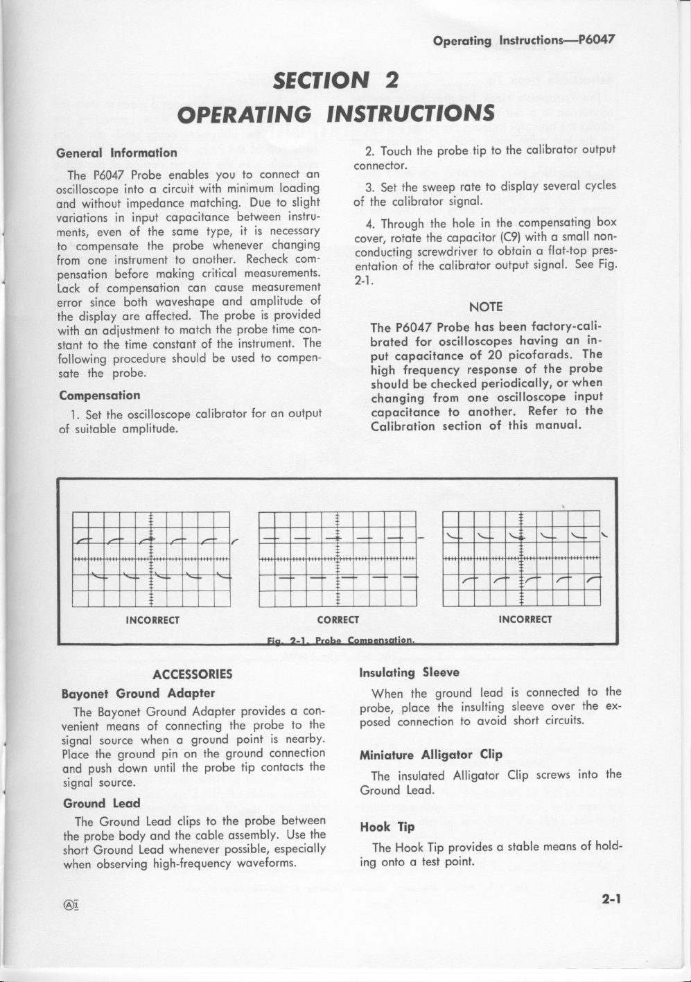
4. Through the hole in the compensating box
cover, rotate the capacitor (C9) with asmall non-
conducting screwdriver to obtain aflat-top pres-
entation of the calibrator output signal. See Fig.
2-1.
NOTE
The P6047 Probe has been factory-cali-
brated for oscilloscopes having an in-
put capacitance of 20 picofarads. The
high frequency response of the probe
should be checked periodically, or when
changing from one oscilloscope input
capacitance to another. Refer to the
Calibration section of this manual.
INCORRECT
ACCESSORIES
Bayonet Ground Adapter
The Bayonet Ground Adapter provides acon-
venient means of connecting the probe to the
signal source when aground point is nearby.
Place the ground pin on the ground connection
and push down until the probe tip contacts the
signal source.
Ground Lead
The Ground Lead clips to the probe between
the probe body and the cable assembly. Use the
short Ground Lead whenever possible, especially
when observing high-frequency waveforms.
@i
CORRECT
Fin 2-1 Fromm
INCORRECT
Insulating Sleeve
When the ground lead is connected to the
probe, place the insulting sleeve over the ex-
posed connection to avoid short circuits.
Miniature Alligator Clip
The insulated Alligator Clip screws into the
Ground Lead.
Hook Tip
The Hook Tip provides astable means of hold-
ing onto atest point.
2-1

Operating Instructions—P6047
Retractable Hook Tip
The Retractable Hook Tip provides apositive
connection to atest point. The spring in the tip
allows the operator to leave the probe connected
to the test point while making adjustments or
performing functions elsewhere.
Insulating Tube
When using the probe without one of the
above tips, place an insulating tube over the tip
of the probe to avoid short circuits.
2-2
F9. 2-2. Probe Holder.
Probe Holder
The Probe Holder provides aplace to store the
probe when not in use. After connecting the
probe to the instrument being used, place the
wide half of the Probe Holder around the cable
and slide onto the tapered portion of the cable
assembly near the compensating box. When the
probe is not in use, place the tapered portion
near the probe body into the holder. See Fig.
2-2. p

Maintenance—P6047
SECTION 3
MAINTENANCE
The P6047 Probe is designed to withstand nor-
normal operation and handling and should give
many hours of continuous use without failure.
However, if the probe fails or breaks, replace-
ment parts are available. See Mechanical and
Electrical parts lists in Section 5. Fig. 3-1 and
Fig. 3-2 show location of electrical parts.
Probe Body and Sleeve
Compensating Box
Locking Nut
Compensating Box Cover
Cable Assembly
C1
Fig. 3-1. Probe Assembly, 3.5-foot Cable.
Replacing Cable Assembly
It the coaxial cable between the probe and
compensating box should fail, the cable assembly
is available complete with fittings and cable
reliefs. Replace the cable assembly as follows:
1. Remove the compensating box cover by
unscrewing the locking nut.
2. Remove the snap ring holding the compen-
sating box to the cable assembly.
3. Unsolder the connection to the end of the
cable assembly, using aheat sink, and separate
the compensating box from the cable assembly.
4. Unscrew the probe body and sleeve assem-
bly from the other end of the cable assembly.
3-]

Maintenance—P6047
5. Unsolder the parallel resistor and capacitor
from the cable assembly, again using aheat
sink.
6. Install the new cable assembly by reversing
the above procedure.
7. After the probe is re-assembled, compen-
sate as described in Section 2. Then compensate
for high frequencies according to the procedure
given in Section 4.
Replacing Components
To replace any electrical parts in either the
compensating box or the probe tip you will need
aphillips head screwdriver, apair of long-nose
pliers, and asoldering iron.
Avoid excessive heat and repeated soldering
on the circuit board to preserve the bond be-
tween the conducting material and the board.
Probe Body and Sleeve
Fig. 3-2. Probe Assembly, 6-foot Cable.
3-2

Calibration—P6047
SECTION 4
CALIBRATION
The P6047 has been designed for use with
instruments having an input impedance of 1
megohm paralleled by 15 to 20 picofarads,
and is factory-calibrated for 20 picofarads. The
high frequency response of the probe should
be checked periodically, or when changing from
one oscilloscope input capacitance to another.
Equipment Required
1. Fast-rise Test Oscilloscope with sweep rate
of 0.1 ,usec/cm and 10X magnification, such
as Tektronix Type 454 or Type 647A with
10A2A and 1132A plug-in units.
2. 500 Pulse Generator (Tektronix Type 109).
3. 60 nanosecond Transmission Line (Tektronix
Type 113 Delay Cable).
4. Two 509 Coaxial Cables—5 nanosecond
lengths of RG-8A/U with GR connectors. (017-
0502-00).
5. GR-to-BNC Adapter (017-0063-00).
6. 509 BNC Termination (011-0049-00).
7. BNC-to-Probe Adapter (013-0084-00).
8. Reactance Meter (Tektronix Type 130).
9. Constant Amplitude Signal Generator (Tek-
tronix Type 191).
10. 509 Coaxial Cable—with BNC connectors
(012-0057-00).
NOTE
Before completing the high-frequency
calibration, adiust C9 (low-frequency
compensation capacitor) as described
in Section 2.
1. High Frequency Calibration
a. Using the two RG-8A/U cables, connect
the Type 113 Delay Cable to the Type 109
Charge Line connectors. Connect the GR-to-
Type 109
d) e
O
4.)
Type 113
Test Oscilloscope
GR-to-BNC
adapter
017-0063-00
50 S! BNC
termination
01 1-0049-00
BNC-to-probe
adapter
013-0084-00
P6047 Probe
Fig. 4-1. Block Layout of test equipment.

Calibration—P6047
BNC adapter, the 509 termination, and the
BNC-to-probe adapter to the output of the Type
109. Connect the P6047 Probe to the test oscil-
loscope input connector and insert the probe
tip into the probe adapter. See Fig. 4-1.
b. Set the test oscilloscope controls as fol-
lows:
Triggering Mode Normal
Slope +
Coupling AC
Source Internal
Time/cm 0.1 yrs
Variable (Time/cm) Calibrated
10X Magnifier Off
Volts/cm 20 mV
c. Set the Type 109 Voltage Range switch to
5, Pulse Polarity to +, and adjust test oscillo-
scope Triggering Level for astable display.
Adiust Type 109 Amplitude for 4cm of deflec-
tion.
d. Using anon-conducting screwdriver, adiust
R4, R7, R9, and C5 for the best flat-top and
leading edge on the waveform. See Fig. 4-2.
2. Ringing, Rounding, and Overshoot Check
With the controls set as described in the
previous step, check ringing, rounding, and
overshoot for £370, in addition to that of the
test oscilloscope.
3. Risetime Check
The P6047 is designed to have abandwidth
of 290 megahertz and arisetime of 1.2 nanosec-
onds. Since this response is considerably faster
than that of the test equipment commercially
available, the probe risetime must be calculated
from comparison of system bandwidth measure-
ments taken with and without the probe.
a. With the reactance meter, measure the
input capacitance of the oscilloscope or plug-in
unit being used (C1 in the following formula).
b. Assuming that the source impedance of
the constant amplitude signal generator used
to measure the bandwidth is 259 (509 output
impedance terminated in 50 Q), calculate the
risetime of the input of the oscilloscope by:
tr1 =2.2 RC =2.2 X25 XC1
c. Connect the constant amplitude signal gen-
erator, terminated in 50 Q, to the oscilloscope
input and measure the bandwidth at —3 dB
(BW1 in the following formula).
d. Calculate the risetime of the oscilloscope
when driven by azero source impedance gen-
erator by:
.35 2V2
tr2 =(3W1) —tr12
e. Connect the P6047 Probe to the input of the
oscilloscope and measure, with the reactance
meter, the input capacitance of the probe (C2
in the following formula).
f. Calculate the risetime of the input of the
probe by:
tr3 =2.2 RC =2.2 X25 XC2
9. Connect the P6047 Probe to the output of
the constant amplitude signal generator, ter-
minated in 50 S2, and measure the bandwidth
at —3 dB (3W2 in the following formula).
INCORRECT CORRECT INCORRECT
Fig. 4-2. High Frequency Calibration.
4-2

h. Calculate the risetime of the P6047 Probe
when driven by a zero source impedance gen-
erator by:
.35 2I2
“'4 :(M) —tr22 —l’l"32 /
4. Attenuation Check
a. Connect the BNC-to-probe adapter and
probe to the Calibrator output (set to 1volt).
Calibration—P6047
b. With the Volts/cm control set to 20 mV,
display several cycles of the Calibrator wave-
form.
c. Check for a5cm display on the test os—
cilloscope, :2%. This specification does not
include any error present in the test oscillo-
scope Calibrator or input attenuator.
4-3

PROBE BODY COMPENSATINC-A BOX
3.5 FOOT CABLE
PROBE BODY COMPENSATINC‘: BOX
6FOOT CABLE
P6047 IOX PROBE.

Electrical Parts List—P6047
ELECTRICAL PARTS 3.5-FOOT CABLE
Values are fixed unless marked Variable.
Tektronix Serial/Model No.
th. No. Part No. Disc Description
Capacitors
Tolerance :20% unless otherwise indicated.
C'l1 281-0645-00 8.2 pF Cer 500 V1-025 pF
C5 281-0091-00 2-8 pF, Var Cer
C7 281-0634-00 10 pF Cer 500 V1-0.25 pF
C9 281-0093-00 5.5-18 pF, Var Cer
Inductors
Ll 276—0528-00 Core, Ferramic Suppressor 0.1 ,uH
L2 276-0507-00 Core, Ferramic Suppressor 0.6 ,uH
L5 *108-0424-00 350 nH
Resistors
Resistors are fixed, composition, ilO‘X, unless otherwise indicated.
R1 1325—0021 -00
R4 31 1-0634-00
R7 31 1-0635-00
R9 31 1-0609-00
l/4W Prec l‘70
1Also available in Attenuator Assembly, Tektronix Part No. *206-0147-00.

Electrical Parts List—P6047
ELECTRICAL PARTS 6-FOOT CABLE
Values are fixed unless marked Variable.
Tektronix Serial/Model No.
th. No. Part No. Eff Disc Description
Capacitors
Tolerance :20"/" unless otherwise indicated.
C12 281 -0663-00 10.4 pF Cer 500 V1"/0
C5 281-0093-00 5.5-18 pF, Var Cer
C6 281 -0619-00 1.2 pF Cer 200 V
C7 281 -0634-00 10 pF Cer 500 V1-0.25 pF
C9 281-0093-00 5.5-18 pF, Var Cer
Inductors
Ll 276-0528-00 Core, Ferramic Suppressor 0.1 ,uH
L3 *108-0452-00 4turns on Ferrite
L5 *108-0424-00 350 nH
Resistors
Resistors are fixed, composition, i10% unless otherwise indicated.
R12 325~0021-00 9M9 1/4 WPrec 1"/0
R4 311-0634-00 500 Q, Var
R7 311-0635-00 1k9, Var
R9 311-0609-00 2k9, Var
2Also available in Attenuator Assembly, Tektronix Part No. *206-0157—00.
5-2 ®§

Mechanical Party—P6047
PROBE AND STANDARD ACCESSORIES
REF. TEKTRONIX SERIAL/MODEL NO. gDESCRIPTION
NO. PART NO. EFF. DISC. Y. 12 3 45
PROBE PACKAGE
1—10 010-0211-00 1PROBE PACKAGE, P6047, 3.5 foot
010-0217-00 lPROBE PACKAGE, P6047, 6foot
------ -package includes:
PROBE ONLY
1010-021200 1PROBE, P6047, 3.5 foot
010-0218-00 1PROBE, P6047, 6foot
STANDARD ACCESSORIES
2013-0090-00 1HOOK TIP, retractable
3175-0124-00 1CABLE, ground lead, 5inch
4175-0263-00 1CABLE, ground lead, 3inch
5013-0085-00 1ADAPTER, bayonet ground
6166-0404-00 2TUBE, insulating, molded
7344-0046-00 2CLIP, probe
8166-0433-00 X6746 1SLEEVE, insulating, gnd strap
9206-0114-00 1TIP, probe
10 352-0090-00 1HOLDER, probe
006-0351-00 1BAG, plastic, 4x6inches (not shown)
070-0628-01 1MANUAL, instruuction (not shown)
®i

Mechanical Parts—P6047
REPLACEABLE PARTS (3.5 foot)
IE
0
REF. TEKTRONIX SERIAL/MODEL NO. 1- DESCRIPTION
N0. PART NO. EFF. DISC. Y. 1234 5
010-0212-00 PROBE, P6047, 3.5 foot
...... probe includes:
1204-0252-00 BODY AND SLEEVE ASSEMBLY
2206-0147-00 ASSEMBLY, attenuator
1
1
1
-assembly includes:
210-1004-00 2WASHER, guide
214-0592-00 1CONTACT, wire form
------ 1CAPACITOR, C1
1RESISTOR, R1
175-0406-00 1CABLE ASSEMBLY, 3.5 foot
015-0097-00 1ASSEMBLY, compensating box
------ -assembly includes:
1ASSEMBLY, connector, BNC
-assembly includes:
1PLUG, probe, BNC
11 358-0072-00 1BUSHING, insulator, BNC 0.323 inch long
12 214-0109-01 1PIN, probe contact, male
13 166-0217-00 1TUBE, spacer, insulator
1
1
1
mwmuv;w
10 134-0044-00
14 132-0081-00 NUT, BNC
15 354-0270-01 RING, front
mounting hardware: (not included w/ring)
SCREW, set, 6-32 x1/8 inch, H55
16 213-0020-00
17 354-0273-00
18 441-0712-00
19 200.0721-00
20 354-0271-00
21 354-0272-00 RING, external, 0.467 inch ID
22 670-0132-00 ASSEMBLY, circuit board
------ -assembly includes:
BOARD, circuit, unwired
mounting hardware: (not included w/assembly)
SCREW, thread forming, 2-32 x1/4 inch, PHS
LOCKWASHER, split, #2
WASHER, flat, 0.090 |Dx0.188 inch OD
WASHER, fiber, 1/8 ID x13/64 inch OD
INSULATOR, fish paper (not shown)
RING, external, 0.625 inch ID
CHASSIS, compensating box
COVER, compensating box
RING, locking
_._._._._._.
23 213-0120-00
24 210-0053-00
25 210-1008-00
26 210090600
214-0939—00
#NMNNI
'—‘
6'2 1135

Mechanical Parts—P6047
REPLACEABLE PARTS (6 foot)
IE]
0
REF. TEKTRONIX SERIAL/MODEL NO. TDESCRIPTION
NO. PART NO. EFF. DISC. Y123 4 5
010-0218-00 IPROBE, P6047, 6foot
------ -probe includes:
I204-0252-00 l BODY and SLEEVE ASSEMBLY
2206-0157.00 ASSEMBLY, attenuator
...... -assembly includes:
3210-1004-00 2WASHER, guide ‘
4214-0592-00 CONTACT, wire form
5------ CAPACITOR, CI
6...... RESISTOR, RI
7I75~0427-00 CABLE ASSEMBLY, 6foot
8 0i5-OO97—00 ASSEMBLY, compensating box
assembly includes:
ASSEMBLY, connector, BNC
assembly includes:
PLUG, probe, BNC
BUSHING, Insulator, BNC, 0.323 inch long
PIN, probe contact, male
TUBE, spacer, insulator
NUT, BNC
RING, front
mounting hardware: (not included w/ring)
SCREW, set, 6-32 x1/2 inch, HSS
I0 134-0044—00
I I 358007200
12 2I4-0109-0I
I3 166—0217-00
14 132-0081-00
IS 354-0270-01
16 213-0020-00 _..
_._‘_a_._-_..
_.,
_._._._.
I7 354-0273-00
I8 441-0712-00
I9 200-0721-00
20 354-027I -00
2I 354-027200 RING, external, 0.467 inch ID
22 670-0132—00 ASSEMBLY, circuit board
------ -assembly includes:
388-0863-00 BOARD, circuit, unwired
------ -mounting hardware: (not included w/assembly)
23 ZII-OOOI-OO SCREW, 2-56x ‘/,. inch, RHS
24 210.005300 LOCKWASHER, split, #2
25 210-1008-00 WASHER, flat, 0.090 ID x0.I88 oinch OD
26 2I0-0906-00 WASHER, fiber, 1/8 ID xl3/64 inch OD
214-0939-00 INSULATOR, fish paper (not shown)
RING, external, 0.625 inch ID
CHASSIS, compensating box
COVER, compensating box
RING, locking
_._._._._....
dMNMN

This manual suits for next models
4
Table of contents
Other Tektronix Accessories manuals

Tektronix
Tektronix P7330 User manual

Tektronix
Tektronix P5122 User manual

Tektronix
Tektronix TPP0500 User manual

Tektronix
Tektronix GeoProbe G10 Owner's manual

Tektronix
Tektronix Trimode TDP7700 Series User manual

Tektronix
Tektronix P5200A User manual

Tektronix
Tektronix P6122 User manual

Tektronix
Tektronix P5100A User manual

Tektronix
Tektronix TPP1000 User manual

Tektronix
Tektronix P6013 User manual