manuals.online logo
Brands
  1. Home
  2. •
  3. Brands
  4. •
  5. Tektronix
  6. •
  7. Accessories
  8. •
  9. Tektronix TPP0500 User manual

Tektronix TPP0500 User manual

xx Operating Information
The TPP0500 & TPP1000 10X Passive Probes are
high impedance probes with 10X attenuation that are
designed for use with Tektronix DPO/MSO4000B &
DPO/MSO5000 series ground-referenced oscilloscopes.
Connect the probe as shown in the illustrations below.
Compensating the Probe
You should compensate the probe after you attach it to an
oscilloscope for the first time, or after you have changed
the probe tip cartridge.
1. Connect the probe to an oscilloscope channel.
2. On MSO/DPO5000 instruments:
a. Connect the probe to the probe compensation output
terminals on the oscilloscope front panel.
b. Select Vertical > Probe Cal....
c. Select the channel number tab of the channel that you
connected the probe to.
d. In the Calibration section, click Calibrate Probe.
On MSO/DPO4000B instruments:
a. Press the Channel Menu front panel button for the
channel that you connected the probe to.
b. Push the More button until Probe Setup is selected.
c. Push the Calibrate Probe button and follow the
on-screen instructions.
If the probe compensation fails, verify that the signal
and ground connections are secure at the Probe Comp
connections on the oscilloscope. Also check that the ground
connection is secure at the probe head, the rigid or pogo
tip is secured tightly in the probe head, and the hook tip is
securely connected to the tip.
Standard Accessories
WARNING. To avoid electric shock when using the probe
or accessories, keep fingers behind the finger guard of
probe body and accessories.
Item Description
Probe tips
The rigid tip (gray tip) is
pre-installed on the probe.
The pogo tip (white tip) is
spring-loaded for compliant
testing of circuit boards.
Reorder part numbers:
206-0610-xx (rigid tip)
206-0611-xx (pogo tip)
Insulator sleeve
Unscrew this sleeve to
replace the probe tips. (See
procedure on next page).
Reorder Tektronix part
number 342-1194-xx
Hook tip
Press the hook tip onto the
probe tip and then clamp
the hook onto the circuit.
Rating: 300 V CAT II
Reorder Tektronix part
number 013-0362-xx
Micro hook tip
Use this tip to access test
points in tight spaces. Press
the hook tip onto the probe
tip and then extend the
pincers around the circuit.
Rating: 300 V CAT II
Reorder Tektronix part
number 013-0363-xx
Universal IC cap
Use this cap to prevent
shorting the probe tip
between IC pins.
Press the cap on the probe
tip until it snaps on, and
then spin the cap to expose
the probe tip toward the IC
lead.
Reorder Tektronix part
number 013-0366-xx
Item Description
Ground springs
To limit aberrations on high
frequency signals caused
by ground path inductance,
bend the spring to reach
nearby ground connections
(<0.75 in, long; <0.25 in,
short). Reorder Tektronix
part numbers:
016-2028-xx (long, 2 ea.)
016-2034-xx (short, 2 ea.)
Ground lead, with
alligator clip
Secure the lead to the probe
head ground and then to
your circuit ground.
Reorder Tektronix part
number 196-3521-xx
Color bands
Use these bands to identify
the oscilloscope channel at the
probe head.
Reorder Tektronix part number
016-0633-xx (5 pairs)
Optional Accessories
The accessories shown below are available for the probes
and are rated ≤30 V unless indicated otherwise.
Accessory
Part
number
MicroCKT Test Tip 206-0569-xx
BNC to Tip Adapter,
Unterminated
013-0367-xx
Circuit Board Test
Point/PCB Adapter
016-2016-xx
Chassis-Mount
Probe Test Jack
131-4210-xx
6” Clip-on
Ground Lead
196-3198-xx
12” Alligator
Ground Lead
196-3512-xx
Wire, spool,
32 AWG
020-3045-xx
TPP0500 & TPP1000
500 MHz and 1 GHz 10X Passive Probes
Instructions
x
*P071280901*
071-2809-01
Interchanging the Probe Tip
WARNING. To reduce the risk of shock, disconnect the
probe before changing the probe tips.
For optimal performance, do a probe compensation after the
tip has been replaced.
Specifications
Table 1: Electrical and mechanical specifications
Characteristic TPP0500 TPP1000
Bandwidth (–3 dB) 500 MHz 1GHz
System rise time (typical) <700 ps <450 ps
System input capacitance Rigid tip: 3.9 pF ±0.3 pF
Pogo pin tip: 5.1 pF ±0.5 pF
System attenuation accuracy 10:1 ±2.2%
Probe series resistance @DC 9.75 MΩ±0.5%
System input resistance @DC 10 MΩ±2%
Propagation delay ~5.67 ns
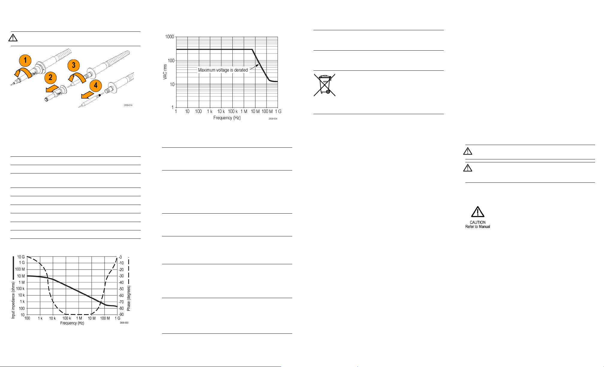
Maximum input voltage 300 VRMS CAT II
Cable length 1.3 m ±3 cm
Performance Graphs
Table 2: Environmental specifications
Characteristics Description
Temperature
Operating
Nonoperating
–15°Cto+65°C(+5°Fto+149°F)
–62 °C to +85 °C (–80 °F to +185 °F)
Humidity
Operating 5% to 95% relative humidity (%RH) up to
+30 °C, 5% to 75% RH above +30 °C up
to +65 °C. Noncondensing
Nonoperating 5% to 45% RH above +65 °C up to +85
°C. Noncondensing
Altitude
Operating
Nonoperating
3.0 km (9,842 ft) maximum
12.2 km (40,000 ft) maximum
Table 3: Certifications and compliances
Characteristics Description
EC
Declaration
of
Conformity
Compliance was demonstrated to the following
specification as listed in the Official Journal of
the European Communities:
Low Voltage Directive 2006/95/EC:
EN61010-031/A1: 2008
Measurement
Category
Product
Examples
CAT III: Distribution-level mains, fixed
installation
CAT II: Local-level mains, appliances, portable
equipment
CAT I: Circuits not directly connected to mains.
Characteristics Description
Pollution
Degree 2
Do not operate in environments where cond-
uctive pollutants may be present (as defined in
IEC 61010-1). Rated for indoor use only.
Additional
Safety
Standards
UL61010-031;2010
CAN/CSA C22.2 No. 61010-031:07/A1:2010
IEC61010-031; IEC 61010-031/A1:2008
Equipment Recycling. This product complies
with the European Union’s requirements
according to Directive 2002/96/EC on waste
electrical and electronic equipment (WEEE).
For more information about recycling options,
check the Support/Service section of the
Tektronix Web site (www.tektronix.com).
Safety Summary
Review the following safety precautions to avoid injury and
prevent damage to this product or any products connected
to it. To avoid potential hazards, use this product only as
specified. Using the probe or accessories in a manner not
specified could result in a shock or fire hazard.
To Avoid Fire or Personal Injury
Ground-Referenced Oscilloscope Use. Do not float the
reference lead of this probe when using with ground
referenced oscilloscopes (for example, DPO, MSO, and
TDS series oscilloscopes). The reference lead must be
connected to earth potential (0 V).
Connect and Disconnect Properly. Connect the probe output
to the measurement instrument before connecting the probe
to the circuit under test. Disconnect the probe input and
the probe reference lead from the circuit under test before
disconnecting the probe from the measurement instrument.
Avoid Electric Shock. To avoid injury or loss of life, do not
connect or disconnect probes or test leads while they are
connected to a voltage source.
Observe All Terminal Ratings. To avoid fire or shock hazard,
observe all ratings and markings on the product. Consult
the product manual for further ratings information before
making connections to the product.
Avoid Electric Shock. When using probe accessories, never
exceed the lowest rating of the probe or its accessory,
whichever is less, including the measurement category and
voltage rating.
Avoid Electric Overload. To avoid injury or fire hazard, do
not apply potential to any input, including the reference
inputs, that varies from ground by more than the maximum
rating for that input.
Avoid Exposed Circuitry and Do not Operate Without
Covers. Do not touch exposed connections and components
when power is present.
Inspect The Probe And Accessories. Before each use,
inspect probe and accessories for damage (cuts, tears,
defects in the probe body, accessories, cable jacket, etc.).
Do not use if damaged.
Do Not Operate in Wet/Damp Conditions.
Do Not Operate in an Explosive Atmosphere.
Keep Product Surfaces Clean and Dry.
Safety Terms and Symbols Terms in This Manual.
These terms may appear in this manual:
WARNING. Warning statements identify conditions or
practices that could result in injury or loss of life.
CAUTION. Caution statements identify conditions or
practices that could result in damage to this product or
other property.
Symbols on the Product. These symbols may appear on
the product:
Contacting Tektronix
Web site: www.tektronix.com
Phone: 1-800-833-9200
Address: Tektronix, Inc.
Department or name (if known)
14200 SW Karl Braun Drive
P.O. Box 500
Beaverton, OR 97077 USA
Email: [email protected]
Warranty Information
For warranty information, go to
www.tektronix.com/warranty.
Copyright © Tektronix, Inc. All rights reserved. www.tektronix.com

This manual suits for next models

1

Other Tektronix Accessories manuals

Tektronix P5100A User manual

Tektronix

Tektronix P5100A User manual

Tektronix TPR1000 User manual

Tektronix

Tektronix TPR1000 User manual

Tektronix GeoProbe G10 Owner's manual

Tektronix

Tektronix GeoProbe G10 Owner's manual

Tektronix TPP1000 User manual

Tektronix

Tektronix TPP1000 User manual

Tektronix TMSSY2 mPGA479 User manual

Tektronix

Tektronix TMSSY2 mPGA479 User manual

Tektronix P6013 User manual

Tektronix

Tektronix P6013 User manual

Tektronix P6122 User manual

Tektronix

Tektronix P6122 User manual

Tektronix TriMode P7500 Series Manual

Tektronix

Tektronix TriMode P7500 Series Manual

Tektronix P6047 User manual

Tektronix

Tektronix P6047 User manual

Tektronix P5200A User manual

Tektronix

Tektronix P5200A User manual

Tektronix P7330 User manual

Tektronix

Tektronix P7330 User manual

Tektronix THDP0100 User manual

Tektronix

Tektronix THDP0100 User manual

Tektronix Trimode TDP7700 Series User manual

Tektronix

Tektronix Trimode TDP7700 Series User manual

Tektronix P7225 User manual

Tektronix

Tektronix P7225 User manual

Tektronix CT-6 User manual

Tektronix

Tektronix CT-6 User manual

Tektronix P6249 User manual

Tektronix

Tektronix P6249 User manual

Tektronix P5122 User manual

Tektronix

Tektronix P5122 User manual

Popular Accessories manuals by other brands

Carefree of Colorado SL WINDOW AWNING Installation and operation manual

Carefree of Colorado

Carefree of Colorado SL WINDOW AWNING Installation and operation manual

Lafferty 919155SS Installation & operation instructions

Lafferty

Lafferty 919155SS Installation & operation instructions

Ansult 006864 operating instructions

Ansult

Ansult 006864 operating instructions

Hytronik HC438V instruction manual

Hytronik

Hytronik HC438V instruction manual

Pertronic 2251BPI Installation and maintenance instructions

Pertronic

Pertronic 2251BPI Installation and maintenance instructions

ENFORCER SD-9 63 Series manual

ENFORCER

ENFORCER SD-9 63 Series manual

DH Instruments EXTERNAL RESERVOIR FOR PPCH instruction sheet

DH Instruments

DH Instruments EXTERNAL RESERVOIR FOR PPCH instruction sheet

PSI Woodworking Products PKTEACH Kit instructions

PSI Woodworking Products

PSI Woodworking Products PKTEACH Kit instructions

Broan NuTone Overture 1110725 manual

Broan

Broan NuTone Overture 1110725 manual

Visonic GFD-40W installation instructions

Visonic

Visonic GFD-40W installation instructions

wtw visoturb 700 iq operating manual

wtw

wtw visoturb 700 iq operating manual

ETC Echoflex Elaho installation guide

ETC

ETC Echoflex Elaho installation guide

alre KTRTB-211.108 quick start guide

alre

alre KTRTB-211.108 quick start guide

Philips SCF156/01 brochure

Philips

Philips SCF156/01 brochure

Festo SOPA Series operating instructions

Festo

Festo SOPA Series operating instructions

Balluff BOS 50K RD11-S4 Series manual

Balluff

Balluff BOS 50K RD11-S4 Series manual

Nordmann Engineering NRC-5V installation instructions

Nordmann Engineering

Nordmann Engineering NRC-5V installation instructions

POLA G 331033 quick start guide

POLA G

POLA G 331033 quick start guide

manuals.online logo
manuals.online logoBrands
  • About & Mission
  • Contact us
  • Privacy Policy
  • Terms and Conditions

Copyright 2025 Manuals.Online. All Rights Reserved.