manuals.online logo
Brands
  1. Home
  2. •
  3. Brands
  4. •
  5. ENFORCER
  6. •
  7. Accessories
  8. •
  9. ENFORCER SD-9 63 Series User manual

ENFORCER SD-9 63 Series User manual

ENFORCER
®
No Touch Request-To-Exit Sensor
4 SECO-LARM U.S.A., Inc
Example Installation:
Typical installation with an electric lock:
Care and Cleaning for the SD-9x 3 Series Sensor:
The sensor requires special care to ensure reliability and a long operating life.
1. Use a soft, clean cloth for cleaning. Use the mildest type of cleaner a ailable.
2. When cleaning, spray the cleaning solution onto the cleaning cloth instead of the unit.
3. Be sure to wipe off any excess liquid from the sensor. Wet spots or areas may affect the
sensor’s performance.
WARNING: Incorrect mounting which leads to exposure to rain or moisture inside the enclosure
could cause a dangerous electric shock, damage the de ice, and oid the warranty.
WARRANTY This SECO-LARM product is warranted against defects in material and workmanship while used in
normal ser ice for a period of one (1) year from the date of sale to the original consumer customer.
SECO-LARM’s obligation is limited to the repair or replacement of any defecti e part if the unit is returned,
transportation prepaid, to SECO-LARM.
This Warranty is oid if damage is caused by or attributed to acts of God, physical or electrical misuse or abuse,
neglect, repair, or alteration, improper or abnormal usage, or faulty installation, or if for any other reason
SECO-LARM determines that such equipment is not operating properly as a result of causes other than defects in
material and workmanship.
The sole obligation of SECO-LARM, and the purchaser’s exclusi e remedy, shall be limited to replacement or
repair only, at SECO-LARM’s option. In no e ent shall SECO-LARM be liable for any special, collateral, incidental,
or consequential personal or property damages of any kind to the purchaser or anyone else.
NOTICE: The information and specifications printed in this manual are current at the time of publication. Howe er,
the SECO-LARM policy is one of continual de elopment and impro ement. For this reason, SECO-LARM
reser es the right to change specifications without notice.
SECO-LARM is not responsible for misprints or typographical errors.
Copyright © 2014 SECO-LARM U.S.A., Inc. All rights reser ed. This material may not be reproduced or copied,
in whole or in part, without the written permission of SECO-LARM.
SECO-LARM
®
U.S.A., Inc.
16842 Millikan A enue, Ir ine, CA 92606 Website: www.seco-larm.com
Tél: 800-662-0800 / 949-261-2999 Fax: 949-261-7326 Email: sales@seco-larm.com
MiSD
-
9x63
-
KSxQ
_1
40
6
.docx
Order Part # 763-171-5%
PI
T
S
W
1
O erride button is prewired in the factory
No further wiring necessary
Outdoor No Touch
Request-To-Exit Sensor
Manual
Slimline Plate Single Gang Plate European Plate
Language
English
SD
-
9163
-
KSQ
SD
-
9263
-
KSQ
SD
-
9363
-
KSQ
Spanish
SD
-
9163
-
KS1Q
SD
-
9263
-
KS1Q
n/a
French
English
w/ mechanical o erride button
SD
-
9163
-
KS2Q
SD-9163-KSVQ
w
SD
-
9263
-
KS2Q
SD-9263-KSVQ
w
n/a
n/a
w
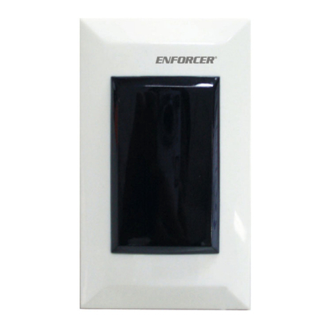
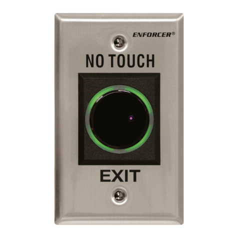
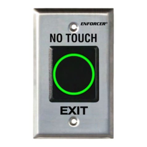
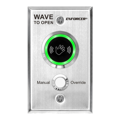
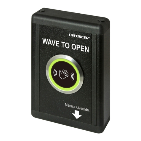
The ENFORCER Outdoor No Touch Request-To-Exit Sensor is a full-featured exit plate which
uses IR technology to allow egress from a protected area or acti ate a de ice with the simple
wa e of a hand. Since it is No Touch, this sensor is ideal for use in hospitals, clinics, labs,
cleanrooms (to reduce the risk of contamination), schools, factories, or offices.
Featuring
:
•Built-in Timer (0.8~30 seconds or toggle)
•Programmable LED (Red to Green or Green to Red)








®
No Touch Request-To-Exit Sensor
2 SECO-LARM U.S.A., Inc
Features:
•
Adjustable sensor range up to 7" (18cm).
•Weather resistant for outdoor use.
•Stainless steel plate.
•1A relay, adjustable trigger duration 0.8~30
seconds or toggle.
•
LED illuminated sensor area for easy
identification.
•Selectable LED colors (turns from red to
green or green to red) to show sensor
acti ated.
Overview:
Specifications:
Power 12~24 VDC
Current
drain
(max.)
Standby 16mA@12VDC / 25mA@24VDC
Triggered 25mA@12VDC / 32mA@24VDC
Relay type Form C dry contact, 1A@30VDC
Response time 10ms
LEDs Standby Red
2
Triggered Green
2
Output time 0.8~30 s, toggle
Range 2”~7” (5~18 cm)
IP rating IP65
3
Temperature range -4°~131° F (-20°~55° C)
Weight
Single Gang 108g
Single
Gang
w/ Mechanical O erride
125g
Slimline 61g
Slimline
w/ Mechanical O erride
77g
European Plate 77g
2
Color function re ersible
3
Front panel only.
1
1
/
2
”
(39mm)
2
3
/
4
”
(70mm)
Sensor range adjustment
Trigger time adjustment
LED control jumper
5-pin connector
Form C Mechanical o erride
1
4
1
/
2
”
(115mm)
1
SD
-
9163
-
KSVQ and SD
-
9263
-
KSVQ
only
SD-9263-KSVQ shown
2
3
/
4
”
(70mm)
4
1
/
2
”
(115mm)
86mm
86mm
European Plate
ENFORCER
®
No Touch Request-To-Exit Sensor
SECO-LARM U.S.A., Inc 3
Wiring Diagram:
Installation:
1. Run four wires through the wall to a single-gang or slimline back-box.
2. Connect the four wires from the back-box to the Request-to-Exit
Sensor according the Wiring Diagram abo e.
3. Screw the plate into the back-box, taking care not to crimp the wires.
4. Remo e clear protecti e film from the sensor before use.
WARNING: Do not connect any de ice that will exceed 1A@30VDC.
Changing the LED Color Jumper Placement:
Slimline Models Single-Gang Models
Adjusting the sensor range and trigger time:
1. The sensor range can be adjusted from
2”~7” (5~18 cm).
2. The trigger time can be adjusted from
0.8 to 30 seconds or toggle
4
.
NOTE: Do not force the adjustment trimpots to turn. Only minimal
force is needed.
Standby: Green
Trigger: Red
Standby: Red
Trigger: Green
(default)
Place here for:
Standby: Green
Trigger: Red
Place here for:
Standby: Red
Trigger: Green
(default)
Red Wire: +12~24 VDC
Brown Wire: Ground (
-
)
Blue Wire: COM
Purple Wire: N.O.
Green Wire: N.C.
Red Wire: +12~24 VDC
Brown Wire: Ground (
-
)
Blue Wire: COM
Purple Wire: N.O.
Green Wire: N.C.
Slimline models
Single gang models
Wiring for No Touch Sensor
(SD-92 3-KSQ shown)
Wiring for No Touch Sensor
with Form C Mechanical O erride Button
(SD-92 3-KSVQ shown)
Sensor range
adjustment
Trigger time
adjustment
4
Set trigger time to maximum
Trigger time: 0.
8
~
3
0 seconds, toggle
4
Default: 0.8 seconds
4
Toggle: turn all the way clockwise
Sensor range:
2”~7” (5~18 cm)
Default: 7” (18cm)

This manual suits for next models

5

Other ENFORCER Accessories manuals

ENFORCER E-931CS22RRCQ User manual

ENFORCER

ENFORCER E-931CS22RRCQ User manual

ENFORCER Seco-Larm SLI E-936-S45RRGQ User manual

ENFORCER

ENFORCER Seco-Larm SLI E-936-S45RRGQ User manual

ENFORCER SECO-LARM SD-9773-KNEVQ User manual

ENFORCER

ENFORCER SECO-LARM SD-9773-KNEVQ User manual

ENFORCER No Touch SD-927PKC-NEQ User manual

ENFORCER

ENFORCER No Touch SD-927PKC-NEQ User manual

ENFORCER E-932-D33TBQ User manual

ENFORCER

ENFORCER E-932-D33TBQ User manual

ENFORCER ENFORCER EVT-RBP-GNCQ* User manual

ENFORCER

ENFORCER ENFORCER EVT-RBP-GNCQ* User manual

ENFORCER Enforcer SD-927PKC-NEQ User manual

ENFORCER

ENFORCER Enforcer SD-927PKC-NEQ User manual

ENFORCER E-931-S50RRLQ User manual

ENFORCER

ENFORCER E-931-S50RRLQ User manual

ENFORCER E-931-S45RRQ User manual

ENFORCER

ENFORCER E-931-S45RRQ User manual

ENFORCER E-931-S50RRGQ User manual

ENFORCER

ENFORCER E-931-S50RRGQ User manual

ENFORCER EFR-E-931-S35RRQ User manual

ENFORCER

ENFORCER EFR-E-931-S35RRQ User manual

ENFORCER E-931-S50RRQ User manual

ENFORCER

ENFORCER E-931-S50RRQ User manual

ENFORCER E-931-S35RRQ User manual

ENFORCER

ENFORCER E-931-S35RRQ User manual

ENFORCER CS-PD115-PAQ User manual

ENFORCER

ENFORCER CS-PD115-PAQ User manual

ENFORCER ECO-LARM RM-R100-TLQ User manual

ENFORCER

ENFORCER ECO-LARM RM-R100-TLQ User manual

ENFORCER E-936-S35RRGQ User manual

ENFORCER

ENFORCER E-936-S35RRGQ User manual

ENFORCER Enforcer SD-927PKC-NEQ User manual

ENFORCER

ENFORCER Enforcer SD-927PKC-NEQ User manual

ENFORCER E-9622-4B25 User manual

ENFORCER

ENFORCER E-9622-4B25 User manual

ENFORCER SLI SECO-LARM SD-9163-KSQ User manual

ENFORCER

ENFORCER SLI SECO-LARM SD-9163-KSQ User manual

Popular Accessories manuals by other brands

OBO Bettermann UDHOME 2 AF Mounting instructions

OBO Bettermann

OBO Bettermann UDHOME 2 AF Mounting instructions

Satel AMD-100 manual

Satel

Satel AMD-100 manual

Perenio PECMS01 Installation and operation manual

Perenio

Perenio PECMS01 Installation and operation manual

PASCO PS-3212 instructions

PASCO

PASCO PS-3212 instructions

Bielay warmness instruction manual

Bielay

Bielay warmness instruction manual

TEFAL Prep'Line 852331 manual

TEFAL

TEFAL Prep'Line 852331 manual

Tuson Cub TPMS Ball Sensor user guide

Tuson

Tuson Cub TPMS Ball Sensor user guide

netvox R718CK2 user manual

netvox

netvox R718CK2 user manual

TeraBee TeraRanger Evo instruction manual

TeraBee

TeraBee TeraRanger Evo instruction manual

Minebea Intec Mini FLEX installation manual

Minebea Intec

Minebea Intec Mini FLEX installation manual

National Semiconductor LM1085 Series Specification sheet

National Semiconductor

National Semiconductor LM1085 Series Specification sheet

Panlux SL2150 Series quick start guide

Panlux

Panlux SL2150 Series quick start guide

System Sensor 22051TEI Installation and maintenance instructions

System Sensor

System Sensor 22051TEI Installation and maintenance instructions

Hypersen HPS-LC010 user manual

Hypersen

Hypersen HPS-LC010 user manual

Craftsman ROUTER MOUNTING KIT Operator's manual

Craftsman

Craftsman ROUTER MOUNTING KIT Operator's manual

Soehnle 68001 operating instructions

Soehnle

Soehnle 68001 operating instructions

Alogic P10QC10P18-BK quick start guide

Alogic

Alogic P10QC10P18-BK quick start guide

iOptron CEM70G quick start guide

iOptron

iOptron CEM70G quick start guide

manuals.online logo
manuals.online logoBrands
  • About & Mission
  • Contact us
  • Privacy Policy
  • Terms and Conditions

Copyright 2025 Manuals.Online. All Rights Reserved.