manuals.online logo
Brands
  1. Home
  2. •
  3. Brands
  4. •
  5. Tektronix
  6. •
  7. Control Unit
  8. •
  9. Tektronix 3B5 User manual

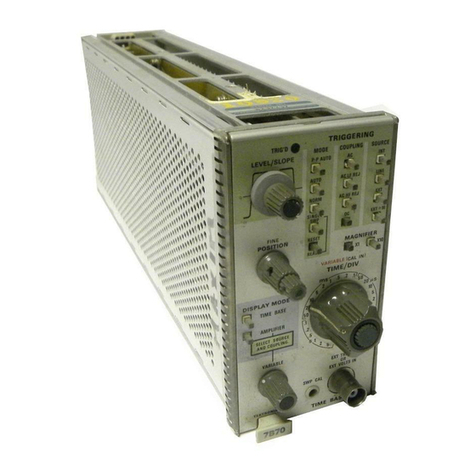
Tektronix 3B5 User manual

Other Tektronix Control Unit manuals
Tektronix 80E01 User manual

Tektronix

Tektronix 80E01 User manual

Tektronix DPO3PWR User manual

Tektronix

Tektronix DPO3PWR User manual

Tektronix TDS3TMT User manual

Tektronix

Tektronix TDS3TMT User manual
Tektronix 80C00 User manual

Tektronix

Tektronix 80C00 User manual

Tektronix Keithley 7706 User manual

Tektronix

Tektronix Keithley 7706 User manual

Tektronix TDS3LIM User manual

Tektronix

Tektronix TDS3LIM User manual

Tektronix ECO170A User manual

Tektronix

Tektronix ECO170A User manual

Tektronix VX4790A User manual

Tektronix

Tektronix VX4790A User manual

Tektronix KEITHLEY 4225-RPM User manual

Tektronix

Tektronix KEITHLEY 4225-RPM User manual

Tektronix KEITHLEY 7700 User manual

Tektronix

Tektronix KEITHLEY 7700 User manual

Tektronix 7B70 User manual

Tektronix

Tektronix 7B70 User manual

Tektronix TM 5006 User manual

Tektronix

Tektronix TM 5006 User manual

Tektronix TM 515 User manual

Tektronix

Tektronix TM 515 User manual

Tektronix 7D11 User manual

Tektronix

Tektronix 7D11 User manual

Tektronix 7A21N User manual

Tektronix

Tektronix 7A21N User manual

Tektronix TM 5003 User manual

Tektronix

Tektronix TM 5003 User manual

Tektronix 80E02 User manual

Tektronix

Tektronix 80E02 User manual
Tektronix 80A01 User manual

Tektronix

Tektronix 80A01 User manual

Tektronix 73A-270 User manual

Tektronix

Tektronix 73A-270 User manual

Tektronix TM 506 User manual

Tektronix

Tektronix TM 506 User manual

Tektronix KEITHLEY 7703 User manual

Tektronix

Tektronix KEITHLEY 7703 User manual
Tektronix DAS MTIF User manual

Tektronix

Tektronix DAS MTIF User manual

Tektronix KEITHLEY 7710 User manual

Tektronix

Tektronix KEITHLEY 7710 User manual

Tektronix TM 506A User manual

Tektronix

Tektronix TM 506A User manual

Popular Control Unit manuals by other brands

Seitz 14A80 user manual

Seitz

Seitz 14A80 user manual

Wilo RS485 Installation and operating instructions

Wilo

Wilo RS485 Installation and operating instructions

Becker CentralControl CC41 Commissioning Instruction

Becker

Becker CentralControl CC41 Commissioning Instruction

SICK CDB650 operating instructions

SICK

SICK CDB650 operating instructions

Panduit NetKey NKP5E88M Series installation instructions

Panduit

Panduit NetKey NKP5E88M Series installation instructions

MX Options Concentric Petite Fitting instructions

MX

MX Options Concentric Petite Fitting instructions

Clean Water Systems Fleck 2510 Installation & start?up guide

Clean Water Systems

Clean Water Systems Fleck 2510 Installation & start?up guide

Fairchild FSB44104A user guide

Fairchild

Fairchild FSB44104A user guide

LEGRAND Wattstopper LMIN-104 installation instructions

LEGRAND

LEGRAND Wattstopper LMIN-104 installation instructions

PMK ATT10BNCS instruction manual

PMK

PMK ATT10BNCS instruction manual

Woodward easYgen Technical manual

Woodward

Woodward easYgen Technical manual

Balluff BNI EIP-502-105-R015 user guide

Balluff

Balluff BNI EIP-502-105-R015 user guide
NXP Semiconductors TWR-LS1021A Getting started

NXP Semiconductors

NXP Semiconductors TWR-LS1021A Getting started

Advantech PCM-3117 Startup manual

Advantech

Advantech PCM-3117 Startup manual

Danfoss MCO 101 manual

Danfoss

Danfoss MCO 101 manual

Moons' Lin Engineering R701P user manual

Moons'

Moons' Lin Engineering R701P user manual

Aventics RV1 operating instructions

Aventics

Aventics RV1 operating instructions

MOTECK CB4M-S user guide

MOTECK

MOTECK CB4M-S user guide

manuals.online logo
manuals.online logoBrands
  • About & Mission
  • Contact us
  • Privacy Policy
  • Terms and Conditions

Copyright 2025 Manuals.Online. All Rights Reserved.

INSTRUCTION
MANUAL
Serial
Number
_____________
TYPE
3B5
AUTOMATIC/
PROGRAMMABLE
TIME
BASE
Tektronix,
Inc.
S.W.
Millikan
Way
•
P.
O.
Box
500
•
Beaverton,
Oregon
97005
•
P one
644-0161
•
Cables:
Tektronix
070-0538-00
666
WARRANTY
All
Tektronix
inst-uments
are
warranted
against
defective
materials
and
workman

s ip
for
one
year.
Tektronix
transformers,
manufactured
in
our
own
plant,
are
war

ranted
for
t e
life
of
t e
instrument.
Any
questions
wit
respect
to
t e
war

ranty
mentioned
above
s ould
be
taken
up
wit
your
Tektronix
Field
Engineer.
Tektronix
repair
and
replacement-part
service
is
geared
directly
to
t e
field,
t erefore
all
requests
for
repairs
and
re

placement
parts
s ould
be
directed
to
t e
Tektronix
Field
Office
or
representative
in
your
area.
T is
procedure
will
assure
you
t e
fastest
possible
service.
Please
include
t e
instrument
Type
and
Serial
or
Model
Number
wit
all
requests
for
parts
or
service.
Specifications
and
price
c ange
privi

leges
reserved.
Copyrig t
c
1966
by
Tektronix,
Inc.,
Beaverton,
Oregon.
Printed
in
t e
United
States
of
America.
All
rig ts
reserved.
Contents
of
t is
publication
may
not
be
reproduced
in
any
form
wit out
permission
of
t e
copyrig t
owner.
I
I
I
I
I
I
I
I
I
I
I
I
I
I
I
I
I
I
I
Type
3B5
CONTENTS
Section
Section
Section
Section
Section
Section
1
2
3
4
5
6
C aracteristics
Operating
Instructions
Circuit
Description
Maintenance
Performance
C eck
Calibration
Abbreviations
and
Symbols
Parts
Ordering
Information
Section
7
Electrical
Parts
List
Mec anical
Parts
List
Information
Section
8
Mec anical
Parts
List
I
j
Section
9
Diagrams
Mec anical
Parts
List
Illustrations
Accessories
t is
manual
Abbreviations
and
symbols
used
in
are
based
on,
or
taken
directly
from,
IEEE
Standard
260
“
Standard
Symbols
for
Units
”
MIL-STD-12B
and
ot er
standards
of
t e
elec

tronics
industry.
C ange
information,
if
any,
is
located
at
t e
rear
of
t is
manual.
■®1
Type
3B5
Fig.
1-1.
Type
3B5
Auto atic/Progra able
Ti e
Base
unit.
Type
3B5
SECTION
1
CHARACTERISTICS
T e
Tektronix
Type
3B5
Automatic/Programmable
Time
Base
unit
provides
automatic
and
programmable
time-base
features,
in
addition
to
conventional
time-base
features,
for
Tektronix
oscilloscopes
w ic
accept
3-series
time-base
units
1
.
T e
Type
3B5
provides
automatic
sweep
rate
and
trigger
seeking
on
Seek
command
eit er
from
t e
front-panel
SEEK
button,
from
a
remote-seeking
probe
(t roug
an
associated
automatic/programmable
amplifier
unit)
or
from
an
external
source
(t roug
eit er
t e
front-panel
PROGRAM
connector
or
t e
program
connector
of
t e
associated
automatic/pro

grammable
amplifier
unit).
All
front-panel
control
functions
(except
variable
sweep
rate)
can
be
externally
programmed
t roug
t e
front-panel
PROGRAM
connector.
T e
MANUAL
TIME/DIV
switc
provides
selection
of
sweep
rates
from
5
seconds/division
to
10
nanoseconds/division
wit
delayed
1
Except
the
Type
561
(SN
5000
and
below).
When
used
in
a
Type
565,
a
vertical
sweep
is
provided.
sweep
magnification
of
10
and
100
times
(up
to
a
maximum
magnified
sweep
rate
of
0.1
microseconds/division).
A
front-panel
illuminated
readout
panel
indicates
sweep
rate,
magnified
sweep
(wit
correct
indication
of
magnified
sweep
rate),
non-triggered
sweep
and
uncalibrated
sweep.
T e
readout
panel
functions
in
all
modes
of
operation.
T e
c aracteristics
w ic
follow
are
divided
into
two
cate

gories.
C aracteristics
listed
in
t e
Performance
Requirement
column
are
c ecked
in
t e
Performance
C eck
and
Calibra

tion
sections
of
t is
manual.
Items
listed
in
t e
Supplemental
Information
column
are
provided
for
reference
use
and
do
not
directly
reflect
t e
measurement
capabilities
of
t is
instrument.
T e
Performance
C eck
procedure
given
in
Section
5
of
t is
manual
provides
a
convenient
met od
of
c ecking
t e
Performance
Requirements
listed
in
t is
section.
T e
following
c aracteristics
apply
over
an
ambient
tempera

ture
range
of
0°
C
to
+50°
C,
except
as
ot erwise
indicated.
Warm-up
time
for
given
accuracy
is
five
minutes.
ELECTRICAL
CHARACTERISTICS
TRIGGERING
C aracteristic
Performance
Requirement
Supplemental
Information
Source
Internal
or
external
Coupling
AC
internal
AC
or
DC
external
Polarity
Sweep
can
be
triggered
from
positive-going
or
negative-going
portion
of
trigger
signal.
Slope
c anged
automatically
eac
time
CHANGE
SLOPE
button
is
pressed.
Mode
Auto
triggering
Normal
triggering
adjustable
for
desired
level
Internal
Trigger
Sensitivity
AUTO
and
AC
0.5
division
of
deflection,
minimum,
50
Hz
to
20
MHz
C ecked
wit
Type
3A5
signal
dis

played,
10
millivolts/division
or
greater
sine
wave.
Typically
—
3
dB
down
at
10Hz
External
Trigger
Sensitivity
AC
1.0
volt,
peak
to
peak,
50
Hz
to
20
MHz
Typically
—
3
dB
down
at
10
Hz
DC
1.0
volt,
peak
to
peak,
10
Hz
to
20
MHz
2.5
volts,
peak
to
peak,
DC
to
10
Hz
Trigger
LEVEL
Control
Range
INT-AC
At
least
+
and
—
10
volts
EXT-AC
At
least
+
and
—
20
volts
EXT-DC
At
least
+
and
—
10
volts
AUTO
Approximately
10%
and
90%
of
trigger
signal
transition
wit
a
minimum
of
0.5
division,
(10
millivolts/division
or
greater)
1
kHz
sine
wave
displayed
wit
Type
3A5
External
Program
Trigger
Level
Range
Same
as
front-panel
range
wit
current
c ange
between
about
0
and
400
micro

amps
External
Trigger
Input
RC
C aracteristics
Approximately
150
kilo ms
paralleled
by
about
22
pF
Maximum
Input
Voltage
at
EXT
TRIG
INPUT
connector
100
volts,
DC
+
peak
AC
1-1
Characteristics
—
Type
3B5
HORIZONTAL
DEFLECTION
SYSTEM
C aracteristic
Performance
Requirement
Supplemental
Information
Sweep
Rates
Manual
Mode
5
seconds/division
to
10
nanoseconds/division
in
27
calibrated
steps.
Sweep
rate
indicated
on
readout
panel
Selected
by
front-panel
MANUAL
TIME/
DIV
switc .
Steps
in
1-2-5
sequence
Seek
Mode
5
seconds/division
to
3.1
microseconds/divi-
sion
in
24
calibrated
sleps.
Sweep
rate
indi

cated
on
readout
panel
Automatically
selected
w en
seek
com

mand
is
received.
Steps
in
1-2-5
sequence
External
Mode
5
seconds/division
to
10
nanoseconds/division
in
27
calibrated
steps.
Sweep
rate
indicated
on
readout
panel
Selected
by
external
program
connected
to
PROGRAM
connector.
Steps
in
1-2-5
sequence
Sweep
Accuracy
(at
25°
C,
±5°)
1
s
to
10
ns
Wit in
±3%
of
indicated
sweep
rate
VARIABLE
control
fully
clockwise
(UN

CAL
readout
off)
and
DLY'D
SWP
MAG
switc
set
to
OFF
(MAG'D
SWP
readout
off).
10,
20
and
50
ns
accuracy
must
be
c ecked
in
accordance
wit
Performance
C eck
5
s
and
2
s
Wit in
±5%
of
indicated
sweep
rate
Variable
Sweep
Rate
Uncalibrated
sweep
rate
to
2.5
times,
or
greater,
t e
indicated
sweep
rate.
s/DIV
read

out
turns
off
and
UNCAL
readout
turns
on
w en
VARIABLE
control
is
not
set
to
CAL
posi

tion
Slowest
sweep
rate
12.5
seconds/divi

sion,
or
greater,
in
5
s
position
Sweep
Lengt
DLY
’
D
SWP
MAG
at
OFF
10.3
to
11.3
divisions
Measured
at
1
ms/DIV
sweep
rate
DLY'D
SWP
MAG
on
12
to
15
divisions
Delayed
Sweep
Magnification
Basic
sweep
rates
between
5
s
and
1
μ
s
can
be
magnified
wit
t e
Del
a
yed
Sweep
Magnifier.
Calibrated
DELAY
control
selects
portion
to
be
magnified.
Basic
sweep
rates
between
5
s
and
10
μ
s
can
be
magnified
100
times;
basic
sweep
rates
between
5
s
and
1
μ
s
can
be
magnified
10
times
Readout
panel
indicates
correct
magni

fied
sweep
rate
Magnified
Sweep
Accuracy
(at
25°
C,
±5°)
1
S
to
1
JUS
Wit in
±
3%
of
sweep
rate
indicated
on
read

out
panel
VARIABLE
control
fully
clockwise
(UN-
CAL
readout
off)
5
s
and
2
s
Wit in
±5%
of
sweep
rate
indicated
on
read

out
panel
Calibrated
Delay
Range
Continuous
from
0
to
10
divisions
from
t e
start
of
t e
trace
Delay
Accuracy
Wit in
±1.5%
of
fu
l
l
scale
at
1
ms/DIV.
Wit in
±3%
of
full
scale
at
all
ot er
sweep
rates
Calibrated
at
1
ms/DIV.
Exclude
first
0.2
division
of
display.
Includes
incre

mental
DELAY
dial
linearity
Incremental
DELAY
Dial
Linearity
Wit in
±0.4%
of
full
scale
Exclude
first
0.2
division
of
display
Delayed
Sweep
Magnifier
Jitter
3
parts
or
less
per
10,000
Equal
to
0.3
division
or
less
w en
meas

ured
wit
x1
00
magnification
at
1
ms/
DIV
basic
sweep
rate
Output
DC
Level
4-180
volts,
±10
volts
Beam
positioned
to
CRT
electrical
center
SEEK MODE
Cycles
Per
Sweep
Between
two
and
six
cycles
wit
nominal
CYCLES/SWEEP
setting
obtained
in
Calibra

tion
procedure
Automatically
selected
w en
seek
com

mand
is
received.
Front-panel
CYCLES/
SWEEP
adjustment
provides
range
of
about
0.5
to
3
times
t is
nominal
setting
Automatic
Seek
Cycling
Time
One
to
two
seconds
W en
seek
command
is
continuous
Automatic
Seeking
Time
500
milliseconds
or
less
wit
10
MHz
sine
wave
input
and
Trigger
Function
switc
set
to
INT-AUTO
Frequency
Range
for
Seek
Mode
Operation
30
Hz
to
20
MHz
Seek
Mono
Pulse
Widt
1.0
to
1.8
seconds
1-2
Characteristics
—
Type
3B5
PROGRAMMABLE
FUNCTIONS
C aracteristic
Performance
Requirement
Supplemental
Information
Trigger
Function
Int
Auto
—
If
not
programmed
Int
AC
—
Terminal
31
Ext
AC
—
Terminal
30
Ext
DC
—
Terminal
28
Grounding
(zero
volt)
digital
logic
to
given
terminal
of
PROGRAM
connector
activates
function
Trigger
Slope
+
Slope
—
If
not
programmed
—
Slope
—
Terminal
27
Trigger
Level
Analog
current
c ange
between
about
0
and
400
microamps
at
terminal
15
of
PROGRAM
connector
provides
same
trig

ger
level
range
as
front-panel
LEVEL
control
Sweep
Rate
Multiplier
X
1
—
Terminal
2
X2
—
Terminal
3
X5
—
Terminal
5
Sweep
multiplier,
sweep
decade
and
decade
enable
must
be
programmed
for
eac
sweep
rate.
Grounding
(zero
volt)
digital
logic
to
given
terminals
of
PRO

GRAM
connector
activates
function
Enable
A
—
Terminal
23
B
—
Terminal
24
Decade
Enable
Logic
Terminal
A
B
1
s
0.1
s
6
10
ms
1
ms
8
0.1
ms
10
μ
s
9
1
μ
s
0.1
μ
s
11
10
ns
26
Horizontal
Position
Analog
current
c ange
between
about
0
and
500
microamps
at
terminal
14
of
PROGRAM
connector
provides
±3
divi

sion
external
orizontal
position
range
Delayed
Sweep
Magnifier
OFF
—
Terminal
33
X10
—
Terminal
34
X
1
00
—
Terminal
36
Grounding
(zero
volt)
digital
logic
to
given
terminal
of
PROGRAM
connector
activates
function
Magnifier
Delay
Analog
current
c ange
between
about
350
and
200
microamps
at
terminal
17
of
PROGRAM
connector
provides
0
to
10
division
external
delay
range
External
Mode
Command
Type
3B5
switc es
to
External
Mode
w en
terminal
21
of
PROGRAM
connector
is
grounded
Remote
Seek
Type
3B5
switc es
to
Seek
Mode
(except
w en
External
Mode
Command
is
present)
w en
terminal
12
of
PROGRAM
connector
is
grounded
Momentary
ground
produces
two
to
six
cycles
(nominal
adjustment)
display;
con

tinuous
ground
recycles
unit
every
one
to
two
seconds
Single
Sweep
+
125-volt
external
oldoff
lockout
ap

plied
to
terminal
7
and
—
12-volts
reset
momentarily
applied
to
terminal
25
of
PROGRAM
connector
provides
single

sweep
operation
ADDITIONAL
FUNCTIONS
AVAILABLE
AT
PROGRAM
CONNECTOR
External
Horizontal
Input
Deflection
factor
Applied
to
terminal
4
of
PROGRAM
connector.
Sweep
lockout
at
terminal
7,
external
unblanking
at
terminal
13
and
orizontal
position
centering
at
terminal
14
also
necessary.
5
volts/division
±5%
Bandwidt
DC
to
750
kHz,
or
greater
Maximum
input
voltage
75
volts,
DC
+
peak
AC
Input
resistance
Approximately
100
kilo ms
1-3
Characteristics
—
Type
3B5
Additional
Functions
(cont)
C aracteristic
Performance
Requirement
Supplemental
Information
Sweep
Out
0.05
milliamp/division,
±10%,
at
termi

nal
16
of
program
connector
2
External
Unblanking
—
12
volts
DC
unblanks
CRT
Apply
to
terminal
13
of
PROGRAM
con

nector
Current
Available
from
PROGRAM
Connector
(maximum)
Supply
Terminal
Current
+
125
V
18
30
mA
-12.2
V
1
75
mA
-100
V
19
1
mA
ENVIRONMENTAL
CHARACTERISTICS
T e
following
environmental
test
limits
apply
w en
tested
in
accordance
wit
t e
recommended
test
procedure.
T is
instrument
will
meet
t e
electrical
performance
requirements
given
in
t is
section
following
environmental
test.
Complete
details
on
environmental
test
procedures,
including
failure
criteria,
etc.,
may
be
obtained
from
Tektronix,
Inc.
Contact
your
local
Tektronix
Field
Office
or
representative.
C aracteristic
Performance
Requirement
Supplemental
Information
Temperature
Operating
0°
C
to
+50°
C
Non-operating
-40°
C
to
+65°
C
Altitude
Operating
15,000
feet
maximum
Non-operating
50,000
feet
maximum
May
be
tested
during
non-operating
temperature
tests
Vibration
Operating
Vibrate
for
15
minutes
along
eac
axis
at
a
total
displacement
of
0.015
inc
(1.9
g
at
50
c/s)
wit
t e
frequency
varied
from
10-50-10
c/s
in
one-minute
cycles.
Hold
at
any
resonant
point
for
t ree
minutes.
If
no
resonant
points
are
found,
vibrate
at
51)
c/s
for
t ree
minutes
on
eac
axis.
Instrument
secured
to
vibration
platform
during
test.
Total
vibration
time
about
55
minutes.
S ock
Non-operating
One
s ock
of
30
g,
one- alf
sine,
11
milli

second
duration
along
eac
major
axis.
Guillotine
type
s ock
Transportation
Package
vibration
Meets
National
Safe
Transit
type
of
test
w en
correctly
packaged
Vibrate
for
one
our
slig tly
in
excess
of
1
g
Package
s ould
just
leave
vibration
sur

face
Package
drop
Drop
from
a
eig t
of
30
inc es
on
one
corner,
all
edges
radiating
from
t at
corner
and
all
flat
surfaces
Total
of
10
drops
MECHANICAL
CHARACTERISTICS
Si ilar
output
available
at
ter inal
18
of
the
interconnecting
plug.
C aracteristic
Information
Construction
C assis
Aluminum
alloy
Panel
Aluminum
alloy
wit
anodized
finis
Circuit
boards
Glass-expoxy
laminate
Dimensions
Fits
3-series
compartments
of
560-
series
Oscilloscopes
Connectors
EXT
TRIG
INPUT
BNC
PROGRAM
37-terminal
connector.
Mates
wit
Cinc
No.
DC-37P-C33
(Tektronix
Part
No.
131-0422-00)
STANDARD
ACCESSORIES
Standard
accessories
supplied
wit
t e
Type
3B5
are
listed
on
t e
last
pullout
page
at
t e
rear
of
t is
manual.
For
optional
accessories
available
for
use
wit
t is
instrument,
see
t e
current
Tektronix,
Inc.
catalog.
1-4
SECTION
2
OPERATING
INSTRUCTIONS
General
Infor ation
To
effectively
use
t e
Type
3B5,
t e
operation
and
capa

bilities
of
t e
instrument
must
be
known.
T is
section
describes
t e
operation
of
t e
front-panel
controls
and
con

nectors,
gives
first
time
and
general
operating
information,
External
Mode
programming
information
and
lists
some
basic
applications
for
t is
instrument.
T e
Type
3B5
operates
wit
t e
indicator
oscilloscope
and
an
amplifier
unit
to
form
a
complete
oscilloscope
system.
W en
used
wit
an
automatic
programmable
amplifier
unit,
a
remote-seeking
probe
and
an
external
programmer,
a
com

plete
system
is
formed
w ic
as
manual,
automatic
seeking,
remote
seeking
and
external
programming
measurement
capabilities.
Installation
CAUTION
Turn
off
t e
oscilloscope
power
before
inserting
or
removing
t e
plug-in
unit.
T e
Type
3B5
is
designed
for
use
in
t e
Horizontal
plug
in
compartment
of
a
560-series
indicator
oscilloscope.
How

ever,
t e
Type
3B5
can
be
inserted
into
t e
Vertical
plug-in
compartment
of
t e
indicator
oscilloscope
to
provide
a
sweep
t at
runs
vertically
on
t e
CRT
screen
(no
blanking
provided
and
instrument
may
not
meet
performance
requirements
given
in
Section
1
if
used
in
t is
manner).
Since
t e
orizontal
and
vertical
deflection
plate
sensitivities
of
t e
oscilloscope
are
different,
t e
Type
3B5
must
be
recalibrated
to
provide
an
accurate
display
for
vertical
deflection
use.
T roug out
t is
manual,
it
is
assumed
t at
t e
Type
3B5
is
used
to
provide
orizontal
deflection
in
t e
conventional
manner.
To
install
t e
Type
3B5
in
t e
oscilloscope,
insert
it
into
t e
plug-in
compartment
and
pus
it
in
as
far
as
possible.
Be
sure
t e
securing
latc
at
t e
bottom
of
t e
panel
is
out
of
t e
way
(turn
knob
counterclockwise)
to
prevent
damage
to
t e
oscilloscope
front
panel.
Secure
t e
plug-in
into
t e
compartment
by
turning
t e
securing-latc
knob
clockwise
until
it
is
tig t.
To
remove
t e
plug-in
from
t e
compartment,
turn
t e
securing-latc
knob
several
turns
counterclockwise.
T en,
pull
t e
plug-in
partially
out
of
t e
compartment
wit
t e
knob
and
take
old
of
t e
plug-in
by
t e
support
rods
to
remove
it
from
t e
oscilloscope.
W enever
t e
Type
3B5
is
transferred
from
one
oscillo

scope
to
anot er,
t e
sweep
calibration
s ould
be
c ecked
and
adjusted
if
necessary
to
provide
accurate
measurements
wit
t e
complete
system.
See
Horizontal
Gain
Adjustment
in
t is
section
for
adjustment
procedure.
Cooling
T e
Type
3B5
does
not
require
special
cooling
ot er
t an
t at
provided
by
t e
indicator
oscilloscope.
W en
operated
wit in
t e
ambient
temperature
range
given
in
Section
1,
t e
Type
3B5
provides
accurate
measurements
(note
excep

tion
for
sweep
accuracy).
FRONT-PANEL
CONTROLS
AND
CONNECTORS
Introduction
All
controls
and
connectors
required
for
t e
operation
of
t e
Type
3B5
are
located
on
t e
front
panel
of
t e
unit
(see
Fig.
2-1).
To
make
full
use
of
t e
capabilities
of
t is
instru

ment,
t e
operator
s ould
be
familiar
wit
t e
function
and
use
of
eac
of
t ese
controls
and
connectors.
A
brief
descrip

tion
of
t e
function
or
operation
of
t e
front-panel
controls
and
connectors
follows.
More
detailed
information
on
con

trol
operation
and
use
is
given
under
General
Operating
Information.
Trigger
Controls
EXT
TRIG
Input
connector
for
external
trigger
signal.
INPUT
Trigger
Function
(not
labeled)
SLOPE
Lever
switc
w ic
selects
t e
trigger
source,
coupling
and
mode.
INT-AUTO
—
Permits
normal
triggering
on
repetitive
waveforms
wit
repetition
rates
ig er
t an
50
Hz.
For
lower
repe

tition
rates
or
w en
t ere
is
no
trigger
signal,
t e
sweep
generator
free
runs
at
t e
sweep
rate
to
w ic
it
is
set
to
pro

vide
a
reference
trace.
Auto
Trigger
lig t
indicates
w en
unit
is
in
t e
auto
trigger
mode.
INT-AC
—
Sweep
triggered
by
internal
sig

nal
from
amplifier
unit.
Trigger
circuit
rejects
DC
and
attenuates
AC
signals
below
about
50
Hz.
EXT-AC
—
Sweep
triggered
by
external
sig

nal
applied
to
t e
EXT
TRIG
INPUT
con

nector.
Trigger
circuit
rejects
DC
and
attenuates
AC
signals
below
about
50
Hz.
EXT-DC
—
Sweep
triggered
by
external
sig

nal
applied
to
t e
EXT
TRIG
INPUT
con

nector.
Trigger
circuit
accepts
AC
and
DC
signals.
(+)
and
(
—
)
lig ts
indicate
w ic
slope
of
t e
trigger
signal
starts
t e
sweep.
W en
t e
(
—
)
lig t
is
on,
t e
sweep
can
be
trig

gered
on
t e
negative-going
slope
of
t e
trigger
signal;
t e
(+)
lig t
indicates
t at
t e
sweep
can
be
triggered
on
t e
positive

going
slope
of
t e
trigger
signal.
Trigger
slope
is
c anged
by
pressing
t e
CHANGE
SLOPE
button
in
t e
center
of
t e
LEVEL
control.
2-1
Operating
Instructions
—
Type
3B5
Fig,
2-1.
Front-panel
controls
and
connectors
of
the
Type
3B5.
I
I
I
I
I
I
I
I
I
I
I
I
I
I
I
I
I
2-2