manuals.online logo
Brands
  1. Home
  2. •
  3. Brands
  4. •
  5. Tektronix
  6. •
  7. Control Unit
  8. •
  9. Tektronix TM 5006 User manual

Tektronix TM 5006 User manual

Other manuals for TM 5006

1

Other Tektronix Control Unit manuals

Tektronix 80A01 User manual

Tektronix

Tektronix 80A01 User manual

Tektronix 80E02 User manual

Tektronix

Tektronix 80E02 User manual

Tektronix VX4287 User manual

Tektronix

Tektronix VX4287 User manual

Tektronix TDS3LIM User manual

Tektronix

Tektronix TDS3LIM User manual

Tektronix VX4237 User manual

Tektronix

Tektronix VX4237 User manual

Tektronix TM 504 User manual

Tektronix

Tektronix TM 504 User manual

Tektronix 7B70 User manual

Tektronix

Tektronix 7B70 User manual

Tektronix 7B15 User manual

Tektronix

Tektronix 7B15 User manual
Tektronix ECO170A User manual

Tektronix

Tektronix ECO170A User manual

Tektronix TM 515 User manual

Tektronix

Tektronix TM 515 User manual

Tektronix TM 5003 User manual

Tektronix

Tektronix TM 5003 User manual

Tektronix VX4342 User manual

Tektronix

Tektronix VX4342 User manual

Tektronix 80C14 User manual

Tektronix

Tektronix 80C14 User manual

Tektronix TM 501 User manual

Tektronix

Tektronix TM 501 User manual

Tektronix TM 506 User manual

Tektronix

Tektronix TM 506 User manual

Tektronix KEITHLEY 4225-RPM User manual

Tektronix

Tektronix KEITHLEY 4225-RPM User manual

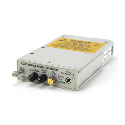
Tektronix 80A02 User manual

Tektronix

Tektronix 80A02 User manual

Tektronix 73A-851 User manual

Tektronix

Tektronix 73A-851 User manual

Tektronix L3 User manual

Tektronix

Tektronix L3 User manual
Tektronix VX4240 User manual

Tektronix

Tektronix VX4240 User manual

Tektronix 7S11 User manual

Tektronix

Tektronix 7S11 User manual
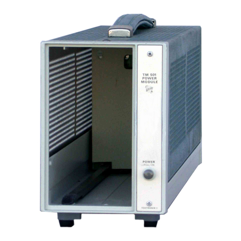
Tektronix DAS MTIF User manual

Tektronix

Tektronix DAS MTIF User manual
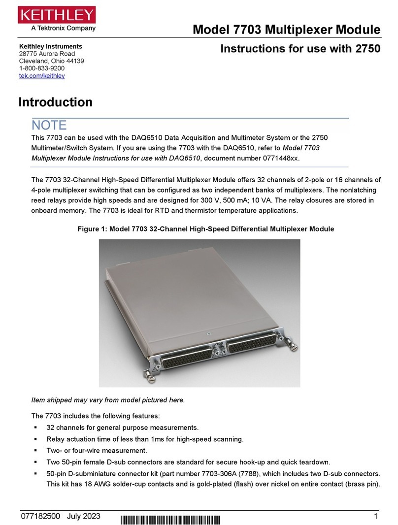
Tektronix KEITHLEY 7703 User manual

Tektronix

Tektronix KEITHLEY 7703 User manual
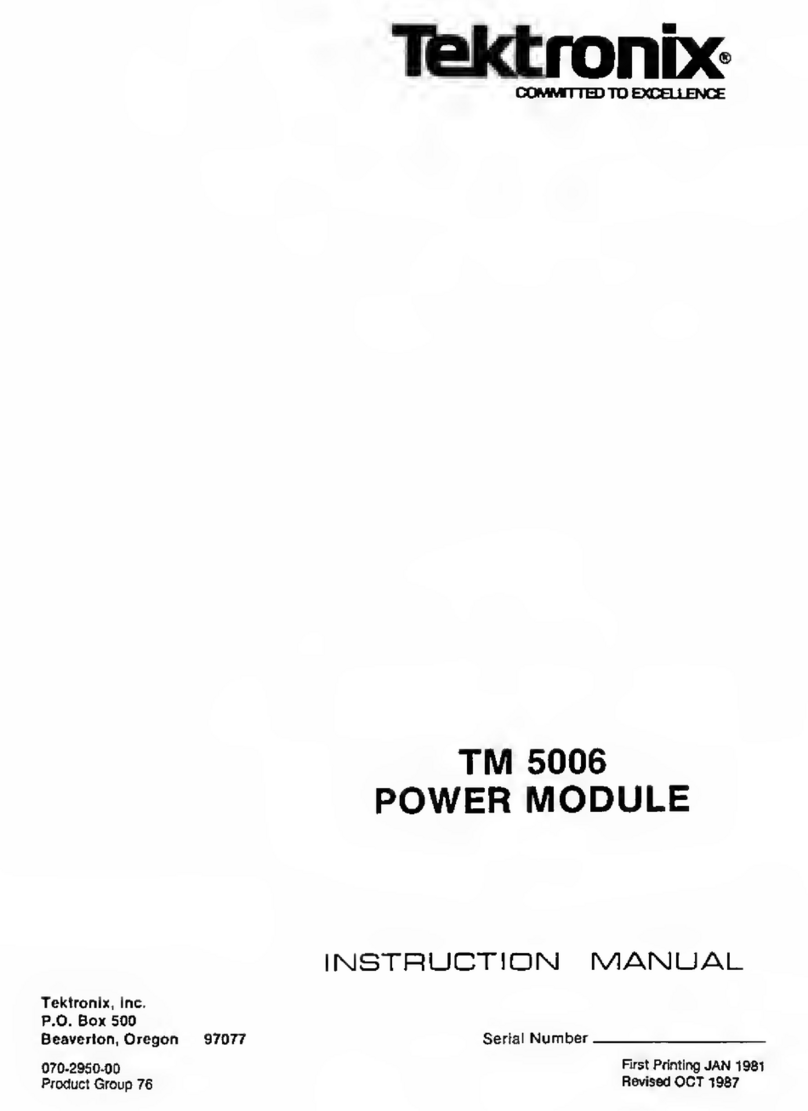
Tektronix 80A05 User manual

Tektronix

Tektronix 80A05 User manual

Popular Control Unit manuals by other brands

Seitz 14A80 user manual

Seitz

Seitz 14A80 user manual

Wilo RS485 Installation and operating instructions

Wilo

Wilo RS485 Installation and operating instructions

Becker CentralControl CC41 Commissioning Instruction

Becker

Becker CentralControl CC41 Commissioning Instruction

SICK CDB650 operating instructions

SICK

SICK CDB650 operating instructions

Panduit NetKey NKP5E88M Series installation instructions

Panduit

Panduit NetKey NKP5E88M Series installation instructions

MX Options Concentric Petite Fitting instructions

MX

MX Options Concentric Petite Fitting instructions

Clean Water Systems Fleck 2510 Installation & start?up guide

Clean Water Systems

Clean Water Systems Fleck 2510 Installation & start?up guide

Fairchild FSB44104A user guide

Fairchild

Fairchild FSB44104A user guide

LEGRAND Wattstopper LMIN-104 installation instructions

LEGRAND

LEGRAND Wattstopper LMIN-104 installation instructions

PMK ATT10BNCS instruction manual

PMK

PMK ATT10BNCS instruction manual

Woodward easYgen Technical manual

Woodward

Woodward easYgen Technical manual

Balluff BNI EIP-502-105-R015 user guide

Balluff

Balluff BNI EIP-502-105-R015 user guide
NXP Semiconductors TWR-LS1021A Getting started

NXP Semiconductors

NXP Semiconductors TWR-LS1021A Getting started

Advantech PCM-3117 Startup manual

Advantech

Advantech PCM-3117 Startup manual

Danfoss MCO 101 manual

Danfoss

Danfoss MCO 101 manual

Moons' Lin Engineering R701P user manual

Moons'

Moons' Lin Engineering R701P user manual

Aventics RV1 operating instructions

Aventics

Aventics RV1 operating instructions

MOTECK CB4M-S user guide

MOTECK

MOTECK CB4M-S user guide

manuals.online logo
manuals.online logoBrands
  • About & Mission
  • Contact us
  • Privacy Policy
  • Terms and Conditions

Copyright 2025 Manuals.Online. All Rights Reserved.

TM
5006
POWERMODULE
Francais
Deutsch
Get other manuals https://www.bkmanuals.com
7~I~ro
nb
c
Te
k
t
r
o
n
ix,
Inc
.
Ρ
.
Ο
.
Box
500
B
eaverton,
O
r
ego
n
97077

Serial
N
u
m
ber
COMMITTED
TO
EXCELLENCE
PLE
AS
E
CHECK
F
O
R
CHANGE
INF
O
RM
ATIO
N
AT
THE
RE
A
R
O
F
T
H
IS
M
A
NU
A
L
.
TM
5006
P
O
WER
M
OD
ULE
F
ra
n
cais

Deutsc
h

θ
*
0
I
N
ST
RU
CTIO
N
M
A
NU
A
L
070-2950-00

First
Pr
inting
J
A
N
1981
Pr
oduct
G
r
oup 76

R
evised
OCT
1987
Get other manuals https://www.bkmanuals.com
Co
p
y
r ig
h
t
®
1981
Te
k
t
r
o
n
ix,
I
nc
.
All
r
ig
h
ts
r
ese
r
ve
d
.
Co
n
te
n ts
o
f
t
h
is
pub
licatio
n
m
ay
n
ot
b
e
r
e
pr
o
du
ced
in
any
fo
rm
wit
hou
t
t h
e
w
r
itte
n pe
rm
issio
n
of
Te
k
tr
on
ix,
Inc
.
Pr
o
du
cts
of
Te
ktr
on
ix,
Inc
.
a
nd
itss
ub
si
d
ia
r
iesa
r
ecove
r
e
d
by
U
.S
.
and
fo
r
eig
n p
ate
n
ts
a
nd
/o
r
p
e
nd
i
ng p
ate
n
ts
.
T
EKT
R
O
N
IX,
ΤΕΚ
,
SCO
PE-M
O
B
I
LE,
a
nd
iste
r
e
d
t
r
a
d
ema
rk
s
of
Te
k
t
r
o
n ix
.
Inc
.
a
r
e
r
eg-
Pr
i
n
te
d
in
U
.S .A
.
Sp
ecificatio
n
and pr
ice
change pr
ivileges
are
r
eserved
.
Copy
rig h
t
©
1981
T
EK
TRON
IX
I
NC
.
Τουτ
dr
oits
r
έ
se
rv β
s
.
Le co
n te
nu de
ce
ma
nu
el
ne
pe
u
t
έ
t r
e
r
e
p
ro
du
it
so
υ
s
qu
el
qu
e
fo
r
-
me
que
ce
soit
sans
Ι
'acco
rd
de
Te
k
t r
on
ix
Inc
.
Τουτ
les
pr
odu
its
TEK
T R
ON
IX
τοστ
br
evet
έs
US
et
E
tr
a
nge
r
et
les
logotypes
T
EK
T
R
ON
IX,
ΤΕΚSCO
PE
MO
B
I
LE,
d
έ
p
os
β
s
.
τοστ
Impr
i
m
β
αυκ
U
SA
.
TEKTRONIX
se
r
β
serve
le
dr
oit
de
mod
ifie
r
ca
r
act
β
r
isti
qu
es et pr
ix
cla
n
s
le
ca dr
e
d
e
dέ
velo
ppe
m
ents
tec
hn
o-
logi
qu
es
.
I
NST
RUMEN
TSER
IA
L
NUMBER
S
E
ac
h
inst
r
u
me
n
t
h
asαse
rial
n
um
be
r
onα
p
an
el
i
n
sert,
tag,
o
r
stam
ped
on
t
he ch
assis
.
T
he
fi
r
st
nu
m
be
r
o
r
lette
r
d
esig
n
ates
t
he
coun
try of
ma
n
ufacture
.
T
h
e
last five
digits
of
t
he
se
r
ial
nu
m
be
r
are
assig
n
ed
seq
ue
n
tially
an
d
a
r
e
u
n
i
que
to
eac
h
i
nstr
u
me
n
t
.
T
h
ose
ma
nu
factu
r
ed
in
t
he
Un
ite
d
States
h
ave
six
un
i
qu
e
d
igits
.
T
h
e
coun
try
of
ma
nu
fact
u
re
is
i
d
e
n
tified
as
follows
:
8000000

Te
k
tr
o
n
ix,
I
n
c
.,
B
eaverton,
O
r
ego
n
,
U
SA
100000

Te
k
t
r
o
n
ix
G
u
er
n
sey,
L
t
d
.,
C
h
ann
el
Isla
nds
200000

Te
k
tronix
U
n
ite
d
K
ing
d
om,
L
t
d
.,
L
on
d
o
n
300000

So
n
y/Te
k
tro
n
ix,
J
ap
a
n
Cop
y
r
ig
h
t
©
1981
dur
c
hTe
k
t
r
o
n
ix,
Inc
.
Alle
R
ech
te
vo
rb
e-
h
alte
n
.
De
r
I
nh
alt
d
ieser
Pub
li
k
atio
n
d
art
o
hn
e
Ge
neh
mig
u
ng
νοπ
Tek
t r
on
ix,
I
nc
.
n
ic
h
t
weite
ι
gege
ben
we
rden
.
Pro
duk
te
νοη
Tek
tr
o
n
ix,
Inc
.
und
sei
nen
Toc
h
te
r
gesellsch
afte
n
si
nd
dur
ch US-
υπ
d
A
u
sla
nd
spaten
te
und
/o
d
e
r
sch
web
e
nd
e
P
atente ab
ge
d
ec
k
t
.
TE
KTR
O
N
IX,
ΤΕΚ
,
SCO
PE-M
O
B
I
LE
a
nd

si
nd
gesc
hU
tzte
W
a
r
enzeic
he
n
νοπ
Tek
t r
o
n
ix,
I
nc
.
Ge
druck
t
in
U
.S .A
.
S
p
ezifi
k
atio
n
s-
und
Pr
eis
A
nd
e
run
ge
n
b
lei
b
en vorbeh
alte
n
.
@1981

ΚΓυΙ
fi
εΡ
h

τ
η
F
ρ
T
EK
T
RON
IX,
ΤΕΚ
,
SCO
PE-M
OB
I
LE,
ιάτη
F
Q=~~
i~$

fl
F
τ
-
~
ο
700000

Tek
tron
ix
H
olla
nd
,
NV,
H
eere
nvee
n
,
T
he
N
eth
erlan
d
s
*
Μι
_
τεπιΙδ
1
ι
~τ
±#
,I
R
U
τ
1
15
49(1-
Τ
ti
<

T3tA
Get other manuals https://www.bkmanuals.com
I
N
STRU
CTIO
N
S
D'
U
TI
L
IZATIO
N
...
. .
...
. .
...
. .
...
. .
...
. .
...
. .
...
. .
...
. .
. .
...
...
...
. .
. .
...
. .
...
...
. .
. .
...
. .
...
...
. .
. .
. .
BE
DI
ENUN
GSA
LL
E
IT
UN
G
. .
. .
. .
...
...
.
....
.
...
...
..
..
...
. .
...
...
. .
. .
....
. .
. .
...
...
. .
...
. .
...
..
...
. .
.. .
. .
...
..
...
. .
.. .
. .
. .
ΙΜ #1
V
FA
. .
...
..
. .
....
. .
. .
...
. .
. .
....
.
...
...
. .
. .
....
. .
. .
...
...
.
....
. .
...
. .
....
.
...
...
. .
. .
....
. .
. .
...
. .
. .
....
.
...
...
. .
. .
...
.
. .
TA
BLE
O
F
CO
N
T
E
N
TS
Sect
i
o
n 1
REV
J
AN
1983
Sectio
n 2
L
A
N
G
U
AG
E
S
TM
5006
O
p
tio
n 02
...........
........
2-6
R
e
p
ac
k
agi
ng Information
. .
......
2-6
S
PE
CI
F
ICATIO
N
I
n
st
ru
me
n
t
Descriptio
n
..........
1-1
P
erfo
r
ma
n
ce
Co
nd
itio
ns
.........
1-1
C
h
ap
it
re 2
I
N
STRU
CTIO
N
S
D'
U
TI
L
ISATIO
N
E
lectrical
Characteristics
.
........
1-1
Introduction
..........................................................
2-1
Environmental
Characteristics
.....
1-4
Source
d
'alimentation
.......................................
2-1
Ph
ysical
C
h
aracteristics
.........
1-5
R
em
p
laceme
n
t
d
'
υη
f
u
sible
.............................
2-1
C
h
blage
..................................................................
2-1
U
tilisatio
ns
ur
u
ne
ta
b
le
de
t
r
avail
..................
2-1
O
PER
ATI
N
G
I
N
ST
RU
CTIO
N
S
M
on
tage
en
bale
..................................................
2-1
I
n
stallatio
n
et
r
et
r
ait
d
es
ti
r
oi
r
s
........................
2-3
I
n
tro
d
uctio
n
..........
........
2-1
Com
p
ati
b
ilit
y
avec
les
au
tr
es
fa
m
ilies
...........
2-3
P
owerSo
ur
ce
R
e
q
ui
r
e
m
e
n
ts
.
.
....
2-1
P
e
r
sonn
alisatio
nde
Ι
'i
n
terface
........................
2-6
P
a
nn ea
u
a
rr iy re
....................................................
2-6
Fuse
R
e
p
laceme
n
t
.......
.
.
....
2-1
O
p
tion
02
..............................................................
2-6
Ca
b
li
ng
.................
....
2-1
I
n
st
ru ctio
ns
de
ryemballage
.............................
2-6
P
age
P
age
L
IST
O
F
I
LLU
ST
R
ATIO
NS
.
.....
.
.
.
.
..........
iv
Ta
b
le
Top
Use
.......
.........
2-1
L
IST
O
F
TA
BLE
S
.........
...........
.......
ν
R
ack
mo
un
ti
n
g
I
n
st
ructio
ns
.......
2-1
P
l
u
g-i
n
I
n
stallatio
n
a
nd
R
e
m
oval
...
2-3
O
PER
ATO
R
S
SA
FE
TY
S
UMM
A
RY
.....
........
vi
F
amily
Co
mp
ati
b
ility
.....
.......
2-3
S
ERV
IC
E
SA
FE
TY
S
UMM
AR
Y
...
............. .
vii
Customizi
ng
t
he
I
n
terface
........
2-3
R
ear
Pa
n
el
...........
.
.
......
2-6
Get other manuals https://www.bkmanuals.com
TM
5006
K
apitel
2
TA
BLE
0
F
CO
N
T
EN
TS
(CO
N
T)
BE
DI
ENUN
GSA
NLE
IT
UN
G
W
A
RN
I
N
G
T
h
e
followi
n
g
se
r
vicing instructions
a
r
e
for
use
by
qualified
p
erso
nnel only
.
To
avoi
d
p
e
r
sonal
injury,
do
not
p
e
r
fo
r
m
a
ny
se
r
vicing
ot
he
rt
h
a
n
t
h
at
con-
tained
in
o
p
erati
n
g
instructions
un
less
yo
uare
qualified
to
do
so
.
Se
ί
te
E
i
n
f
O
h
r
un
g
. .
................
2-1
N
etzs
p
annu
ngsve
r
so
run
g
..... .
. .

2-1
A
u
swec
h
seln
de
r
Sic
h
e
ru ng
.
.....

2-1
V
er
ka
b
el
ung
........
.........
2-1
Tisc
hb
etrie
b
....
.
.
........
...
2-1
Anleit
un
g
f
O
r
d
en
Gestellein
b
au
....

2-1
E
in-
u
nd
A
us
b
au
νοη
E
insc
h0
be
n
. .

2-3
K
om
p
ati
b
ilittit
......
...........
2-3
An
p
ass
un
g
d
e
r
Sc
hn
ittstelle
......

2-3
Gertiter
O
c
k
seite
...............

2-6
O
p
tio
n
02
.................. .

2-6
V
ersa
ndh
i
n
weise
..........
....

2-6
Ι
.t
υ
&)
tz
. .
.
. .
......
......
.
.
.......
.
.
.......
.
.
.....
...
2
3

.
......
.......
.
.
.......
.
.
...... .
......
.
.
....
.
.
....

2-
. .
.
.
......
......
. .
.
.......
.
.
....
.
.
....
.
2
".
.
.
.......
.
.
..........
. .
..........
.
2--
.
.......
.
.
.......
...
.
.
........
...
1
L
.~Z~~is
~
ί
z
2
-
"
~
.
0I
R
i)f1'
L
t
.
..........
.
.
....
....... .
.....
2
-
7
5
O
AR
~)
lt
1,1
L
IN
9)
9
b
L
.....
.
.
.....
2-
....
.......
.
. .
...
.
.
..........
...
.
.
. .
7~
η
1-
Γ
ί

~
ά
2-
. .
.
.
....
.
.
.......
.
.
....
.
.
. .
R
~2-
τ
,
g~~

αι
.....
.
.
.......
.
.
. .
.
....
......
.
.
.......
....
2
-
7"i
α
ί
02
α
)
...
.
.
....
.
.
..........
...
.
.
.......
2
-
w
i`t0)*
ιΑ
..
.
. .
...
.
...
...
.
......
.......
.
.
... .
....
2-
REV
J
AN
198
3
P
age
Section 3
T
HE
O
RY
O
F
O
PER
ATIO
N
I
n
t
r
od
uctio
n
..................
3-1
L
i
n
e
Selector
a
nd
60
Hz
Transfo
r
me
r
Ο
.............
3-1
R
ectifie
r
sa
nd
F
ilte
r s 1
......
3
- 1
20
kH
z
output
Stage
1 ..... .
.
3-1
Co
n
t r
ol
L
ogic
an
d Drive
r
s
Ο
.
. .
3-1
Out
pu
t
R
egulator
ο
.........
3-3
Over
v
oltage
a
nd
Overc
u
rre
n
t
Detectors
ο
...............
3-4
Co
n
trol
Circuit
Regulator
Ο
...
3-4
Main
I
n
terface
π
...........
3-5
Section 4
CA
L
I
BR
ATIO
N
P
erfo
r
ma
nce
C
hec
k
Pr
oce
d
ure
....
4-1
I
n
tro
d
uctio
n
................
4-1
Ι
Test E
quipme
n
t
R
e
qu
ire
d
......
4-1
Ι
Test L
oads
fo
r
the P
erforma
nce
Ι
Ch
ec
k
P
roce
d
u
r
e
.
.........
. .
4-1
Ι
P
erforma
n
ce
C
heck
Su
m
m
ary
Ι
S
h
eet
..................
. .
4-2
Ι
I
n
ter
n
al
A
dj
ustme
n
t
P
roce
d
ure
....
4-5
3
Intro
du
ctio
n
...
. .
. .
...
.
.....
4-5
3
Services
Available
...........
4-5
3
Test
E
qu
i
pm
e
n
t
R
e
q
u
ire
d
......
4-5
6
A
dj
u
stme
n
t
Access
..........
.
4-5
6
P
ower
L
imit
Ad
ju
stme
n
t
.......
4-5
6
Section 5
M
AI
NT
EN
ANC
E
L
ine
V
oltage
Selectio
n
..........
5
-
1
Static
Se
n
sitive
Compo
n
ents
....
5-1
Cleaning
..................
5-2
O
b
tai
n
i
n
gRep
laceme
n
t
P
arts
...
5-2
Solderi
n
g
Tec
h
ni
q
ues
....
. .
. .
.
5-3
Semico
ndu
ctors
............ .
5-3
Mu
ltipin
Con
n
ectors
..........
5-3
I
n
str
u
me
n
t
Disassem
b
ly
.......
5-3
Circ
u
it
Tro
ub
les
h
ooti
n
g
. .
.....
5-5
R
ea
r
I
n
terface
Information
. .
.
. .
..
5-10
PWR
I
n
dicato
r
.
. .
.
.........
.
5-10
P
i
n
Assig
n
ments
.........
...
5-10
Get other manuals https://www.bkmanuals.com
REV
J
AN
198
3
TA
BLE
0
F
CO
N
T
EN
TS
(cont)
Sectio
n7
RE
PLACEA
BLEELE
CT
R
ICAL
P
A
R
TS
Sectio
n8
DIAGRA
MS
A
N
D
CI
R
CUIT
B
OA
RD
IL
LUST
R
ATIO
N
S
Sectio
n8
REP
LAC
E
AB
LE
M
E
C
H
AN
ICA
L
P
A
R
TS
Component
Reference
C
h
arts
Sc
he
m
at
i
c
Diag
r
a
m
s
F
i
g
.
1
Exploded
View
Accessories
C
H
A
NGE
I
NF
O
R
M
ATIO
N
Sectio
nβ
OPTIO
N
S
P
age
Int
r
o
du
ct
i
o
n
:
....
.
.. ..........
6-1
Option
02
.... ..
.
..........
6-1
Syste
m
Des
i
gn
Directions
......
6-1
W
i
r
e
U
se
. . . .
.
.
.
...........
β
-1
Get other manuals https://www.bkmanuals.com
TM
5006
IV
LIST
OF
ILLUSTRATIONS
Page
Oute
r
p
a
n
el
removal
....
.
.... .
. .
. .

5-4
G
u
i
de
rail
a
nd
air
b
affle
removal
. .
...

5-4
R
e
m
oval
of
i
n
terface
ci
r
cuit
boa
rd
s
upport
. ........
...
..........
.
5-5
M
ai
n
i
n
terface
ci
r
cu
it
b
oar
d
r
e
m
oval

.
.

5-6
R
ea
r
p
an
el
r
e
m
oval
.......
.
..
.
....

5-6
L
ocatio
n
of
screws
h
ol
d
i
ng
t
he
dc
power
s
up
ply
circ
u
it
b
oar
d to
t
h
e
mai
n
f
r
a
m
e
ch
assis
. .
.
.....
.
.
.
.......
.
. .
.
. .
5-7
Attach
i
n
g
screws
on
b
otto
m
of
m
ai
n
f
r
a
m
e
..........
.
.........
.

5-7
Un
sol
de
r
t
h
ese
wi
r
es
to
r
e
m
ove
h
eat
si
n
k
....
. .
......
.
. . . .
.
....

5-8
Se
r
ies
p
ass
t
r
a
n
sisto
r
locatio
ns
.
T
he
h
ig
h
p
owe
r
co
mp
art
m
en
t
series
pass
t
r
a
n
sisto
r
s
0600
a
nd
0610
a
r
e
on
t
he
r
ig
h
t
si
de
of
t
he
h
eat
si
nk
.
0600
is
t
he
uppe
r
transistor
........
....
.....
.
...
.

5-9
Sc
r
ews
h
ol
d
i
n
g
h
eat
si
nk
to
ci
r
cu
it
b
oa
rd
. .
........
....
.
.. . . .
.
...
5-9
T
r
a
n
sfor
m
e
r
asse
mb
ly
attac
h
i
ng
scr
ews
.
. .
. .
.
...
....
. .
.
. .
.
...
.
.
5-9
PWR
sig
n
al
ti
m
i
n
gd
iag
r
a
m
. .
.
. .
.
...

5-10
Rea
r
i
n
te
r
face
connector
assig
nm
en
ts
.

5-11
R
ea
r
panel
G
P
I
B
connector
J
1110
viewed
fro
m
r
ear
of
power
m
o
du
le
(IEEE
Sta
nd
a
rd
No
.
488)
....
. .
.
.
. .
.
....

5-12
Dc
p
owe
r
s
upp
ly
b
oa
rd
(
Α
11)
Dc
p
owe
r
s
upp
ly
r
eg
u
lato
r
wavefo
rm
s
M
ai
n
i
n
terface
b
oa
rd
(
Α
10)
G
P
I
B
i
n
terco
nn
ect
b
oa
rd
(
Α
16
b
ack
si
d
e)
REV
N
O
V
1984
Fig
.
No
.
TM
5006
Power
Module
..
.
....... .
P
age
viii
F
ig
.
No
.
5-4
21
TM
5006
rear
panel
... ... ........ .
2-2 5-5
2-2
TM
5006
fro
nt
view
. .
.
. .
.
.....
...
.
2-3 5-6
2-3
TM
5006
b
otto
m
view
... ... .
.
. . . .
.
2-4
2-4
TM
5006,
O
p
tio
n
10
overall
d
i
m
en
sio
ns
2-5
5-7
2-5
R
ac
k
latc
h
h
ole
. .
.
... ... ........
2-6
5-8
2-6
Di
m
e
n
sio
ns a
nd
p
ositio
n
i
n
g
of
TM
5006,
5-9
Optio
n
10,
i
n
sta
nd
a
rd
rac
k
.........
2-7
2-7
Rac
km
o
un
t
sli
de
d
etail
.
If
t
he
r
ac
k
has
tapped
h
oles,
t
h
e
b
ar
n
uts
a
r
en
ot
5-10
required
........
.
... ...
.
.....
.
2-8
2-8
R
ac
km
o
un
ti
n
g
sli
de
d
etails
.
.
.......
2-8
5-11
29
Re
m
ovi
ng
and
i
n
stalli
ng
TM
5006,
O
p
tio
n
10,
i
n
r
ac
k
sli
d
es
. . . . ...
.
........
2-9
5-12
2-10
Pl
u
g-i
n
i
n
stallatio
n
a
nd
re
m
oval
......
2-10
211
K
eyi
ng
assig
nm
e
n
ts
forfa
m
il
y
f
un
ctio
n
s
.
One
of
t
he
m
an
y
p
ossi
b
le
sequ
e
n
ce
com
b
i
n
atio
n
s
..... . . .
.
. .
........
2-10
3-1
Various
waveformsa
nd
time
relationships
5-13
fo
r
powe
r
on,
off,
fa
u
lt,
a
nd
low
li
n
e
...
3-2
3-2
I
npu
t
li
ne
conn
ectio
n
sfo
r
110
V
a
nd
220
V
5-14
operation
...
.
.. ...
.
. .
.
.......
.
.
3-3
4-1
P
ossi
b
le
loads
for
u
se
i
n p
erfo
rm
a
n
ce
5-15
chec
kp
r
oce
dur
e
.
See
te
x
t
.
.
........
4-1
5-16
42
Test
set
u
p
fo
rperfo
r
m
a
n
ce
check
steps
1,
5-17
2a
nd
3a
nd
locatio
n
of
conn
ectio
ns
fo
r
a
dj
ust
m
en
t
ste
p
1
.
. .
. .
.
. .
........
44
4-3
Loa
d
s
fo
r
use
i
n
i
n
ternal
8-1
a
dju
st
m
e
n
t
pr
oce
du
re
. .
. .
.........
.
...
4-5
8-2
4-4
A
dj
ust
m
en
t
locatio
n
ill
u
st
r
atio
n
......
...
.
4-6
4-5
Locatio
n
of
voltage
b
uses
............
.
.
4-6
8-3
5-1
L
i
ne
cord o
p
tio
ns
fo
r
t
h
e
TM
5006
....
5-1
8-4
5-2 L
i
n
e
voltage
jump
er p
ositio
ns
.......
5-2
5-3
O
r
ie
n
tatio
n
a
nd
d
isasse
mb
ly
of
mu
lti
p
i
n
conn
ecto
r
s
....
. .
. .
..
.
.....
.
...
5-3
Get other manuals https://www.bkmanuals.com
REV
J
AN
198
3
L
IST
O
F
TA
BLE
S
Ta
b
le
No
.
P
age
1-1
Electrical
C
ha
r
acteristics
. .
.
.
.......
1-1
1-2
En
vi
r
o
nm
e
n
tal
C
ha
racte
r
istics
...
.
...
1-4
1-3
Ph
ysical
C
har
acteristics
.......
.
...
1-5
41
S
uggestedTest
Equ
i
pm
en
t
.........
43
5-1
R
elative
S
u
sce
p
t
i
b
ility
to
Static
Discharge
Da
m
age
. .
.
.
.
...... ......... . . .
5-2
8-1
P
artial
Α
11
Co
mp
one
n
t
R
efe
r
en
ce
C
h
art
8-2
P
artial
Α
11
Co
m
po
nen
t
R
efere
n
ce
C
h
art
8-3
Α
10
Com
po
nen
t
R
efer
en
ce
C
h
art
Get other manuals https://www.bkmanuals.com
ΤΜ
5006
T
he
ge
ne
r
al
safety
information
in
t
h
is
p
art
of
t
he
s
umm
ary
is
fo
r
b
ot
h
operating
and
servicing
personnel
.
Specific
wa
rn
i
ngs and
ca
u
tio
ns
will
b
e
fo
und
throughout
the
m
a
nu
al
w
he
r
e
t
h
ey
apply,
bu
t
m
ay
n
ot
a
p
pea
r
in
t
h
is
s
umm
a
r
y
.
Term
s
1
η
T
h
is
Manual
CA
U
TIO
N
stateme
n
ts
i
den
tify
cond
itio
ns
o
r
pr
acticest
h
at
co
u
l
d
res
u
lt
i
nda
m
age
to
t
h
e
e
qu
i
pm
e
n
t
o
r
other
property
.
W
A
RN
I
N
G
state
m
en
ts
i
de
n
tify
co
nd
itio
ns
o
r
pr
actices
t
h
at
co
u
l
d
r
es
u
lt
i
n
pe
r
so
n
al
i
n
j
u
ry
o
r
loss
of
life
.
Term
s
As
M
a
rk
e
d
onEq
ui
p
me
n
t
CA
U
TIO
N
i
nd
icates
α
pe
r
so
n
al
i
njur
y
h
aza
rd
n
ot
im-
m
ed
iately
accessi
b
le
as
one
r
ea
d
s
t
he
ma
rk
i
n
g,
or
α
h
azar
d
to pr
operty
i
nclu
d
i
n
g
t
hee
qu
i
pm
e
n
t
itself
.
DA
NG
ER
i
nd
icates
α
perso
n
al
i
nj
ury
h
aza
rd
im
m
e
d
iately
accessi
b
le
as
o
n
e
r
ea
d
s
t
he
m
a
rk
i
n
g
.
Symbols
In
T
h
is
Manual
Th
is
sym
b
ol
i
nd
icates
w
he
r
e a
pp
lica
b
le
cautio
nary
o
r
ot
he
r
i
n
formatio
n
is
to
b
e
fo
und
.
Sym
b
ols
As
M
ar
ked
on
Equ
i
p
me
n
t
Vi
Power
So
ur
ce
O
PER
ATO
RS
SA
FE
TY
S
UMM
A
RY
DA
N
G
ER
-
H
ig
h voltage
.
Pr otective
g
r
o
und
(eart
h
)
te
r
mi
n
al
.
ATTENTION
-
refer
to
m
a
n
ual
.
T
h
is pr
o
du
ct
is
i
n
te
nd
e
d
to
ope
rate
f r
o
m
α
p
owe
r
so
ur
ce
t
h
at
will
n
ot
apply
m
o
r
e
t
h
a
n
250
volts
rm
s
betwee
n
t
he
s
upp
ly
co
ndu
cto
r
s
o
r
b
etwee
n
eit
h
e
r
s
upp
ly
co
ndu
cto
r
a
nd
g
r
o
und
.
Α
pr
otective
g
r
o
und
co
nn
ectio
n
byway
of
t
he
g
r
o
und
i
n
g
co
ndu
cto
r
in
t
he
power
cord
is
esse
n
tial
fo
r
safe
ope
r
atio
n
.
Groun
d
i
ng
t
he
Pr
o
du
ct
T
h
is
pro
du
ct is
g
r
o
und
ed
t
hr
o
ugh
t
h
eg
r
o
und
i
ng
co
ndu
c-
tor
of
t
he
p
owe
r cor
d
.
To
avoi
d
elect
ri
cal
sh
oc
k
,
p
l
ug
t
he
power
cor
d
into
α
properly
wired
r
ece
p
tacle
befor
e
conn
ecti
n
g to
t
h
e
p
ro
du
ct
i
np
ut
o
r
output
terminals
.
A
p
rotective
g
r
o
und
conn
ect
i
o
n
b
y
way
of
t
he
g
r
o
und
i
ng
co
ndu
cto
r
in
t
he
p
owe
r
co
rd
is
essential
fo
r
safe
ope
r
a-
tio
n
.
Da
n
ge
r
Arisi
ng
Fr
o
m
L
oss
of
G
r
o
und
Up
o
n
loss of
t
he
pr otective-g
r
o
und
co
nn
ect
i
o
n
,
all
accessi
b
le
co
ndu
ctive
parts
(i
n
cl
ud
i
ng kn
ob
s
a
nd
con-
trols
t
h
at
m
ay appear
to
b
e
i
n
su
lat
i
n
g)
can
r
e
nd
e
r
an
elect
r
ic
sh
oc
k
.
U
se
t
h
e
P
r
ope
r
Fu
se
To
avoi
d
fi
r
e
h
aza
rd
,
use
only
t
he
f
u
se
of
cor
r
ect
ty
p
e,
voltage
rati
nga
nd
current
r
ati
ng
as
specifie
d
in
t
h
e
p
arts
list
fo
r
yo
ur
pr
o
du
ct
.
R
efe
r f
u
se
replacement
to
qu
alifie
d
se
r
vice
personnel
.
Do
N
ot
O
pe
r
ate
In
E
xplos
i
ve At
m
os
ph
e
r
es
To
avoi
d
ex
p
losio
n
,
d
o
n
ot
ope
r
ate
t
h
is
pr
o
du
ct
i
n
an
ex
p
losive
atmos
phe
r
e u
n
less
it
h
as
been
specifically
certifie
d
for
su
c
ho
pe
r
atio
n
.
Do
N
ot
Ope
r
ate
W
it
h
out
Covers
To
avoi
d
pe
r
so
n
al
i
njur
y,
d
o
not
remove
t
he
pr
o
du
ct
cove
r
s or p
a
n
els
.
Do
not oper
ate
t
h
e
product
wit
h
out
t
he
cove
r
sa
nd
p
a
n
els
properly
i
n
stalle
d
.
ADD
J
AN
198
3
Get other manuals https://www.bkmanuals.com
Do
Not
Service
Alone
REV
J
AN
1983
S
ERV
IC
E
SA
FE
TY
S
UMM
A
R
Y
FO
R
Q
U
A
L
I
F
I
E
D
S
E
R
V
IC
E
PER
SO
NNE
L
ONLY
R
eferalso to
t
h
e
preceding
O
p
e
r
ato
r
s
Safety
S
u
mma
r
y
.
Do
n
ot
perform
i
n
ter
n
al
se
r
vice
o
r
a
dju
stme
n
t
of
t
h
is
product
un
less
a
n
ot
he
r
pe
r
so
n
capa
b
le of
r
e
nd
e
r
i
ng
first
ai
da
nd
resu
scitatio
n
is
pr
esent
.
U
se
Ca
r
e
Wh
en
Servici
ng
W
it
hP
ower
On
Da
nge
r
o
u
svoltages
exist
at
seve
r
al
p
oi
n
ts
i
n
t
h
is
pr
od
u
ct
.
To
avoi
d
pe
r
so
n
al
i
njur
y,
d
o
not
to
u
ch
ex
p
ose
d
conn
ec-
tions
a
nd co
m
po
ne
n
ts
w
h
ile
p
owe
r
is
on
.
Power
So
ur
ce
TM
5006
Disco
nn
ect
powe
r
b
efo
r
e
r
e
m
ovi
ng
pr
otective
pan
els,
sol
d
e
r
i
n
g,
α
r
e
p
laci
ng
co
mp
one
nts
.
T
h
is
pro
d
uct
is
i
n
te
nd
e
d
to
ope
r
ate
f r
o
m
α
powe
r
so
ur
ce
t
h
at
will
n
ot
apply
m
o
r
e
t
han
250
volts
rm
sb
etwee
n
the
s
upp
ly
co
ndu
ctors
α
between
eit
he
r
s
upp
ly
conductor
a
nd
g
r
o
und
.
Α
protective
g
r
o
und
connection
bywayof
the
g
r
o
und
i
ng
cond
ucto
r
in
t
he
p
owe
r
cor
d
is
esse
n
tial
fo
r
safe
ope
r
atio
n
. .
Get other manuals https://www.bkmanuals.com