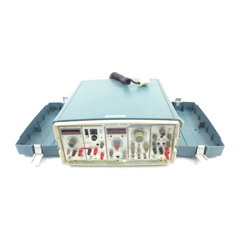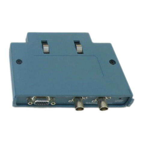
7B70
(SN
B205000
and
Up)
SECTION
2
OPERA
TlNGINSTRUCTIONS
Changeinformation, ifany, affecting thissection willbe found at the rear ofthemanual.
General
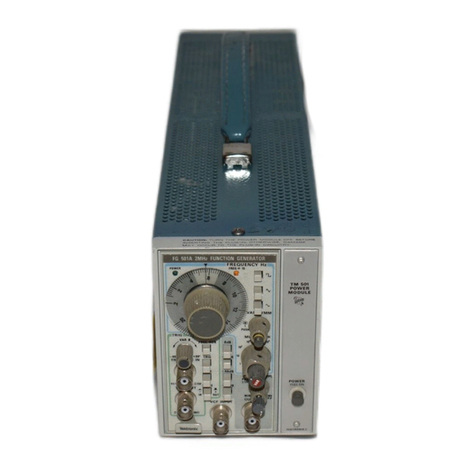
The 7B70 plug-in unit operates with a Tektronix
7000-series indicator oscilloscope and a 7A-series vertical
plug-in unit to form a complete oscilloscope system. To
effectively use the 7B70
its
operation and capabilities
should be known. This section describes the operation of
the front-panel controls, gives first-time and general opera-
ting information and
lists
some basic applications for this
instrument.
l
nstallation
The 7B70
is
designed tooperateinthe horizontal plug-in
compartments of Tektronix 7000-seriesoscilloscopes. The
7B70 can also be installed inavertical plug-incompartment
to provide a sweep that runs vertically on the CRT. How-
ever, when used inthis manner, there
is
no retrace blanking
or internal triggering provision and the unit may not meet
the specifications given in Section
1.
The instructions in
this manual are written for use of the 7B70 inahorizontal
plug-incompartmentof the oscilloscope.
When the 7B70
is
used with an oscilloscope which has
two horizontalplug-incompartments, installthis unit inthe
B (right) compartment. Then, if
a
delaying-sweep unit
is
installed inthe A (DELAYINGTIME BASE)compartment,
delayed-sweepoperation
is
available.The 7870will operate
EXT
TRIG IN
OR
EM
VOLTS
IN
TEKTRONIX
O
-6-
7610
TtME
BASE
I
ele ease/
Latch
Fig.
2-1.
Location
of
release latch.
properly in the A compartment for all horizontal modes of
operation exceptdelaying sweep.
To install the 7B70 into a plug-in compartment, push
it
in until it fits firmly into the indicator plug-in compart-
ment. To remove, pull the release latch (see Fig.
2-11
to
disengage the unit from the indicator and pull
it
out of the
plug-in compartment. Even though the horizontal gain of
the indicator oscilloscope
is
standardized to minimize ad-
justment when insertingplug-in units, the sweep calibration
of the 7870 should be checked when
it
is
inserted intothe
indicator to verify measurement accuracy. The procedure
for checking the unit is given under Sweep Calibration
Check in this section.
FRONT-PANEL CONTROLS
General
All controls requiredfor the operation of the 7870 are
located on the front panel of the unit (see Fig.
2-2).
To
make full use of the capabilities of this instrument, the
opetator should be familiar with the function and use of
each of these controls. A brief description of the front-
panel controls and connector
is
given here. More detailed
information
is
given under General OperatingInformation.
Triggering Controls
LEVELISLOPE Selects the amplitude point and
slope of trigger signal on which the
sweep is triggered. When the indica-
tor line on the outer ring
is
to the
left of center, the sweep is triggered
on the positive-going slope of the
trigger signal, as shown by the
positive-going waveform. To the
right of center, the sweep
is
trig-
gered on the negative-goingslope of
the trigger signal as shown by the
negative-goingwaveform.
TR
IG'D Light indicates that the sweep is
triggered and will produceadisplay
with correct setting of the POSI-
TION control and the controls on
the associated verticalunit and indi-
cator oscilloscope.
Scans
by
ArtekMedia
O
2006
