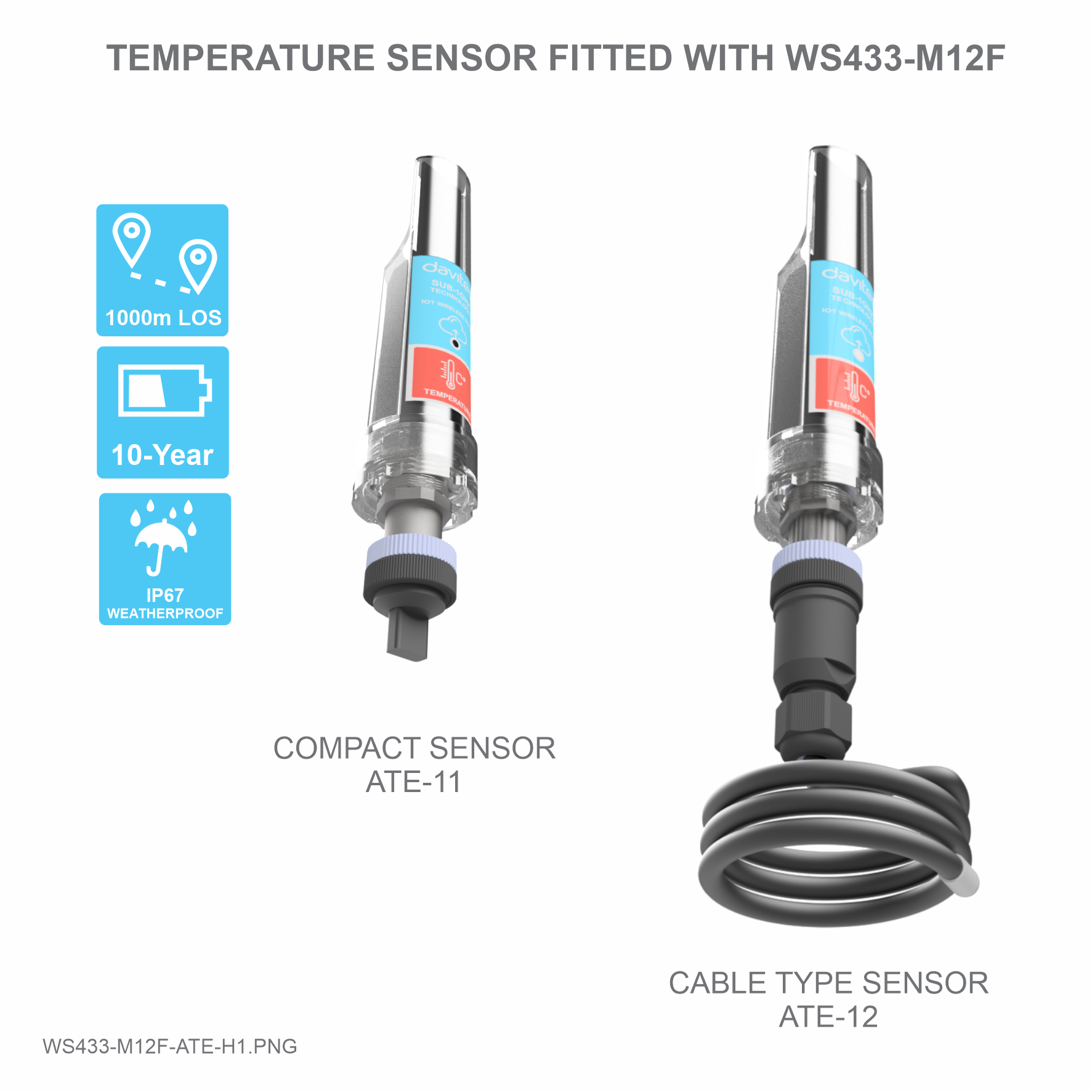
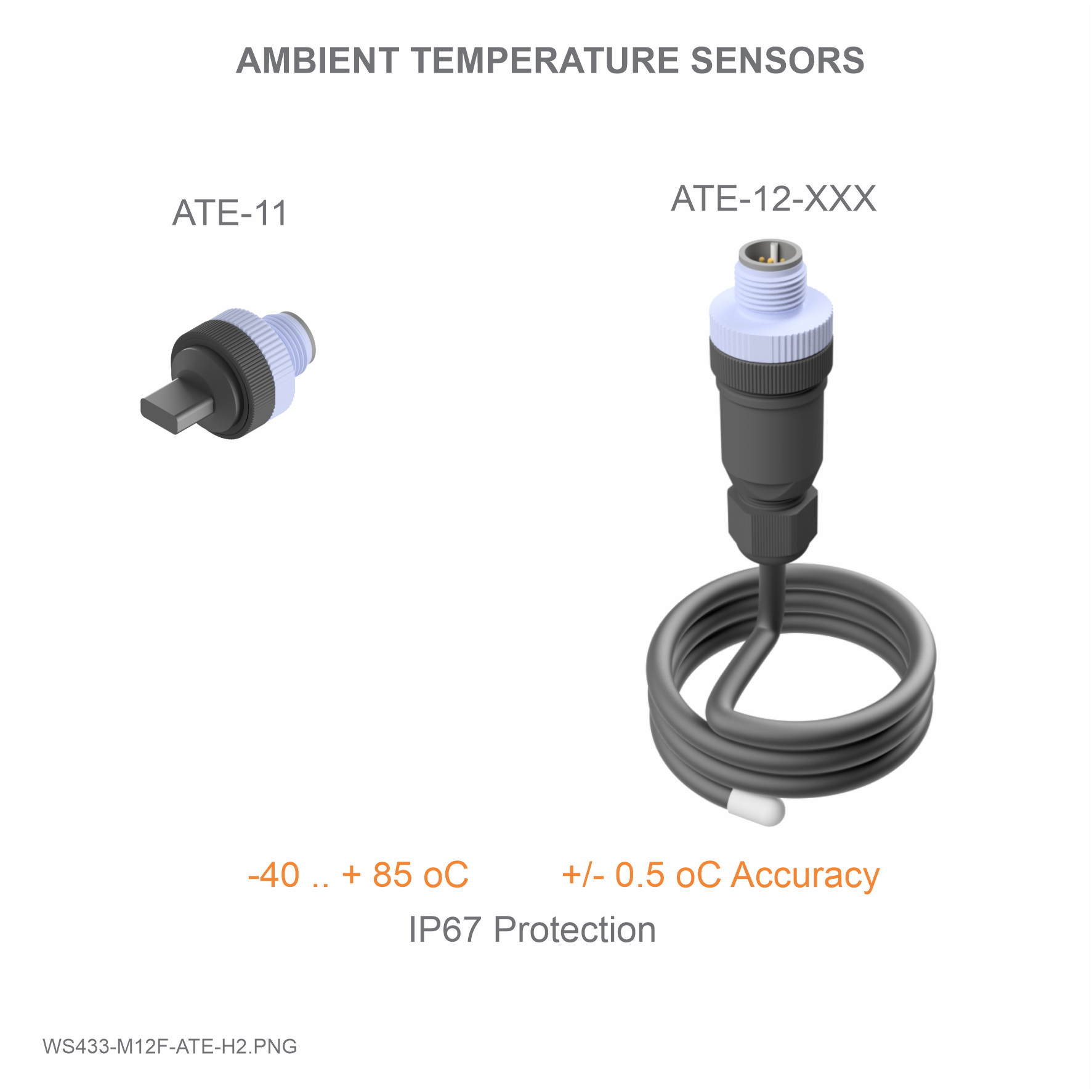
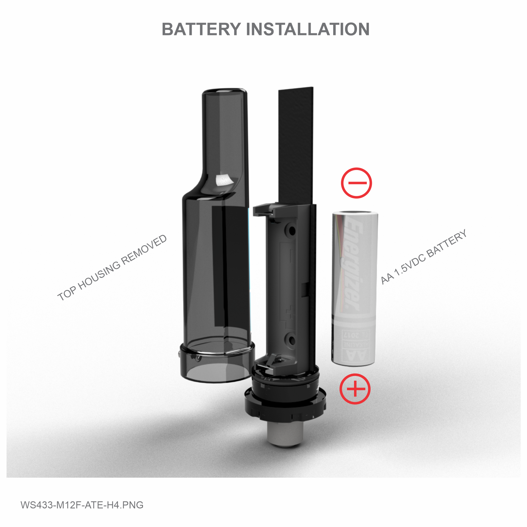
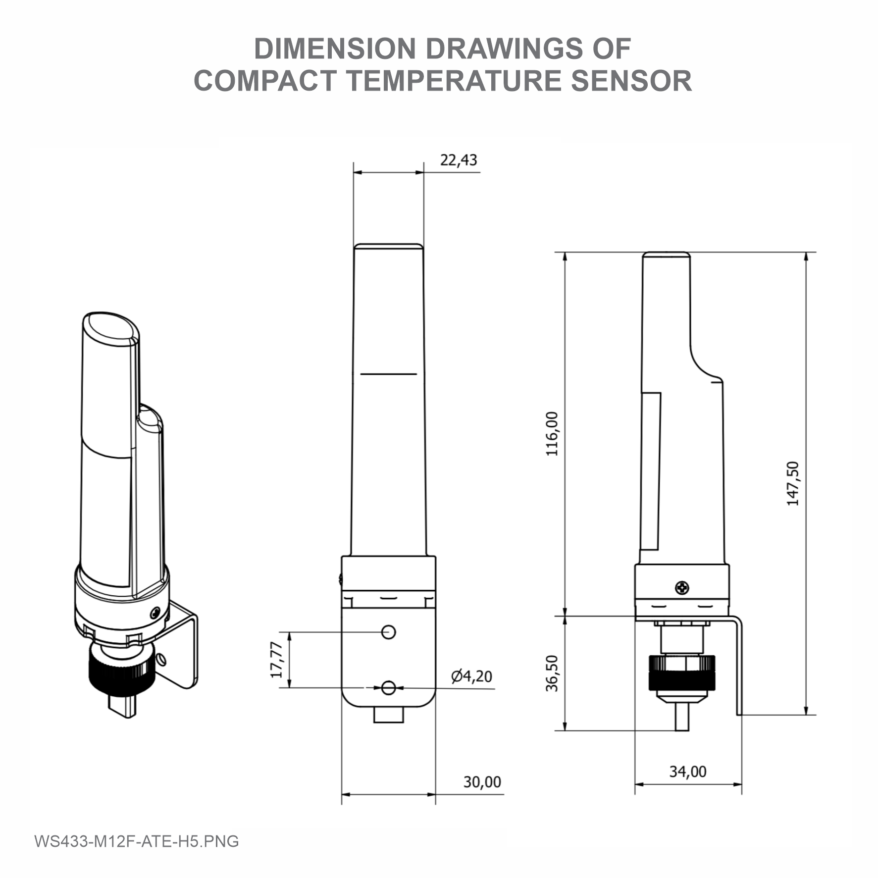
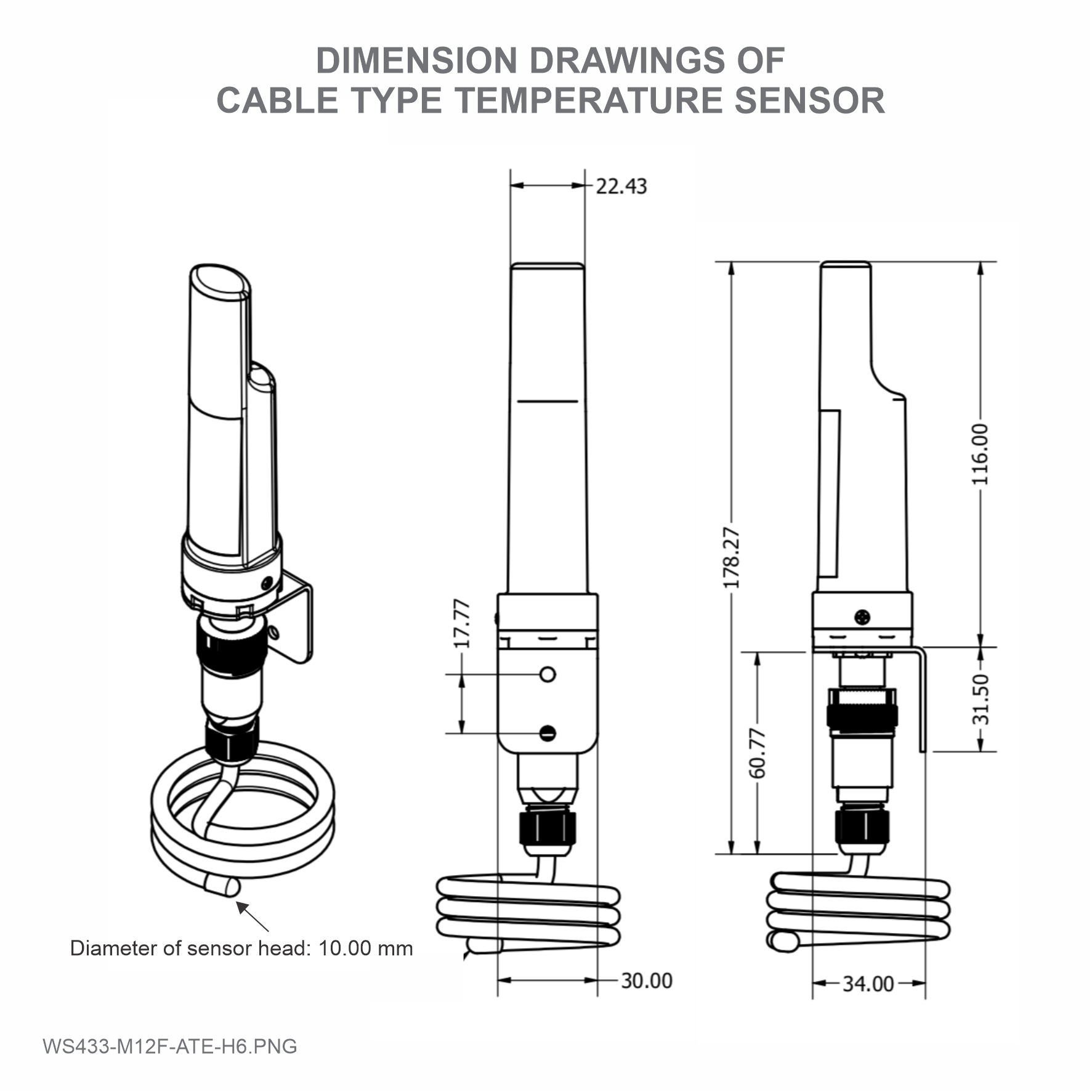
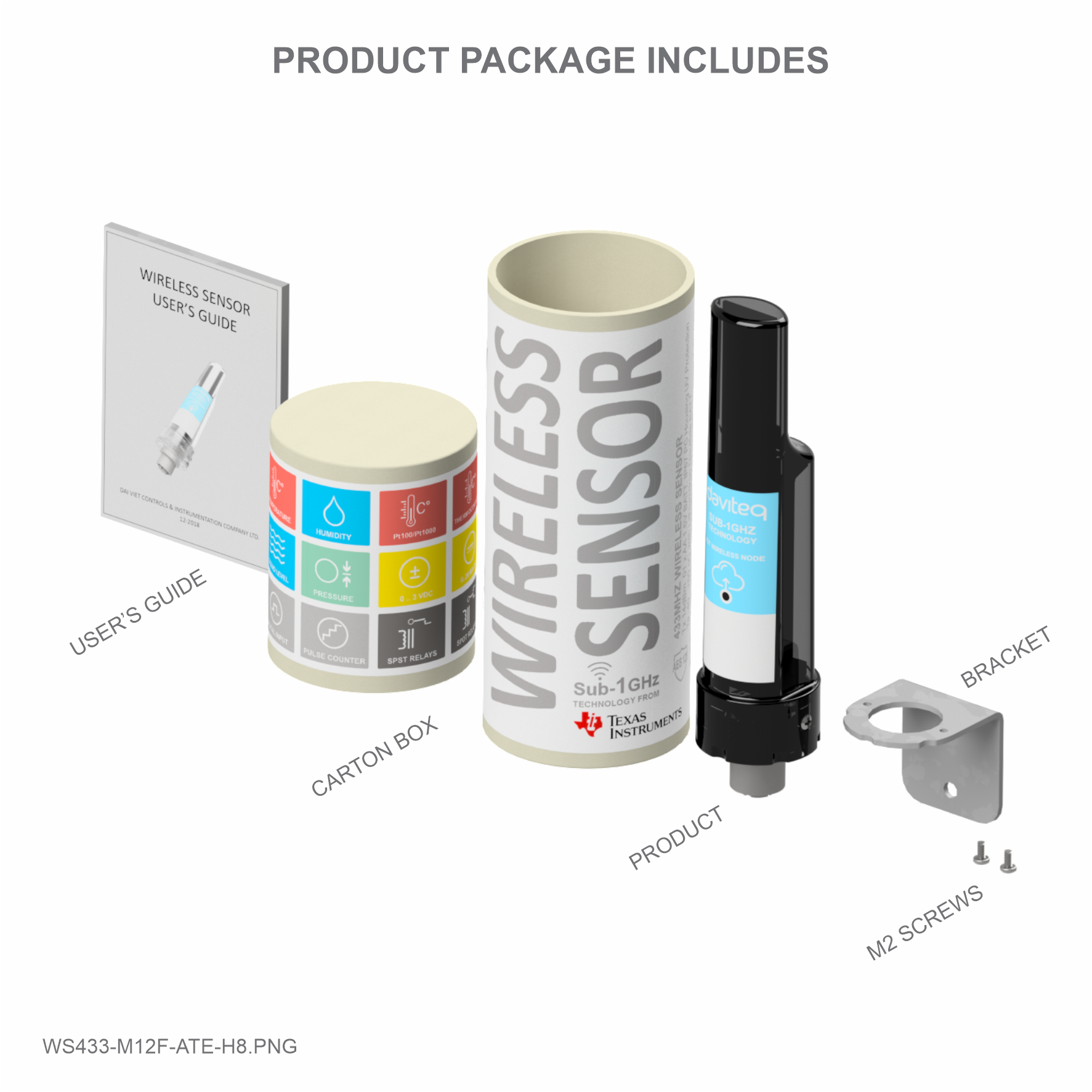
daviteq WS433-M12F-ATE User manual

WS433-M12F-ATE-MN-EN-01
FEB-2020
SKU
WS433-M12F-ATE
HW Ver.
2.5
FW Ver.
5.04
Item Code
WS433-M12F
Wireless Sensor Transmitter 433Mhz, compatible with all DULP sensor
modules, AA 1.5VDC battery, IP67
ATE-11
Compact ambient Temperature Sensor DULP module, M12-male
connector
ATE-12-300
300mm Cable type ambient Temperature Sensor DULP module, M12-
male connector
Notes
* Must order for both wireless transmitter and sensor module
HW Ver.
FW Ver.
Release Date
Functions Change
2.5
5.04
NOV-2019
Change RF data rate by button
Wireless Ambient Temperature Sensor is a combination of wireless sensor transmitter WS433-M12F and ambient
temperature sensor ATE, it utilizes Digital temperature sensor delivers high accuracy measurement in range -35 to +
70oC. The wireless portion is Sub-GHz technology from Texas Instruments allows long range transmission at ultra-low
power consumption. It will connect 2-way wirelessly to the wireless co-ordinator WS433-CL to send data and receiving
the configuration. It can be configured the operation parameters like data sending interval, health check
cycle...remotely from Globiots platform or via ModbusRTU software (thru the WS433-CL). Its default data rate is 50
kbps, can be switched to 625 bps to increase the communication range. It can last up to 10 years with a single AA
battery. There are a lot of applications as environment monitoring for office, warehouse, data center, hospital,
agriculture...
USER GUIDE FOR WIRELESS
AMBIENT TEMPERATURE SENSOR
WS433-M12F-ATE
This document is applied for the following products
1. Functions Change Log
2. Introduction

SENSOR SPECIFICATION :
Sensor
Digital type, factory calibrated, IP67, immersible to ice-
water for quick validation
Measuring range
-35 .. + 70 oC
Accuracy & Resolution
+/- 0.5oC, 0.125oC
Material
PA plastic with PVC cable
Electrical connection
M12-male connector
WIRELESS SPECIFICATION :
Data speed
Up to 50kbps
Tranmission distance, LOS
500m
Antenna
Internal Antenna, 3 dbi
Battery
01 x AA 1.5VDC, up to 10-year operation, depends on
configuration
Frequency Band
ISM 433Mhz, Sub-GHz technology from Texas
Instrument, USA
International Compliance
ETSI EN 300 220, EN 303 204 (Europe) FCC CFR47
Part15 (US), ARIB STD-T108 (Japan)
Security Standard
AES-128
Operating temperature of PCB
-40oC..+60oC (with AA L91 Energizer)
Housing
Poly-carbonate, IP67
Installation method
L-type bracket SUS304 , by M4 screws or double-sided
3M tape (included)
Product dimensions
125x30x30mm
3. Specification

Process of measurement
When the sensor sampling time interval is reached, for example 2 minutes, the node will wake up and switch ON the
power supply to supply the energy to external sensor to start the measurement. Depends on the type and
characteristic of external sensor, the sensor will take a certain time to finish the measurement.
For example, the measurement time is 200mS, after this time, the node will read the value of sensor using I2C, node
will switch OFF power supply to external sensor to save energy.
Once reading the sensor value, the raw data is X, it can be scaled to any engineering value by the following formula:
Y = aX + b
Where
X: the raw value from sensor
Y: the calculated value for parameter 1's value or parameter 2's value
5. Operation principle

a: constant (default value is 1)
b: constant (default value is 0)
So, if there is no user setting for a and b ==> Y = X
The Y value will be compared with Lo and Hi threshold.
Status bytes of sensor Node
Hi-Byte is error code
Error code
Description
0
No error
1
Just exchange the sensor module but node has not been reset ==> please take out the
battery for 20s then install it again to reset node to recognize the new sensor module
2
Error, sensor port M12F shorted to GND
3
Error, sensor port M12F shorted to Vcc
4
Error, sensor port M12F shorted each other
Lo-Byte is sensor type
Error code
Description
0
No error
1
Just exchange the sensor module but node has not been reset ==> please take out the
battery for 20s then install it again to reset node to recognize the new sensor module
2
Error, sensor port M12F shorted to GND
3
Error, sensor port M12F shorted to Vcc
4
Error, sensor port M12F shorted each other
Logic status of parameters
Hi-Byte is Logic status of parameter 1
If parameter 1's value > high threshold 1 => Hi-Byte of Logic status = 1
If parameter 1's value < low threshold 1 => Hi-Byte of Logic status = 0
If parameter 1 is digital => Hi-Byte of Logic status = parameter 1's value
Timer up 1 = (Total time when Hi-Byte of Logic status = 1)
Timer down 1 = (Total time when Hi-Byte of Logic status = 0)
RisingEdge counter 1 = (Counter value when Hi-Byte of Logic status changes from 0 to 1)
FallingEdge counter 1 = (Counter value when Hi-Byte of Logic status changes from 1 to 0)
Lo-Byte is Logic status of parameter 2
If parameter 2's value > high threshold 2 => Lo-Byte of Logic status = 1
If parameter 2's value < low threshold 2 => Lo-Byte of Logic status = 0
If parameter 2 is digital => Lo-Byte of Logic status = parameter 2's value
Timer up 2 = (Total time when Lo-Byte of Logic status = 1)
Timer down 2 = (Total time when Lo-Byte of Logic status = 0)
RisingEdge counter 2 = (Counter value when Lo-Byte of Logic status changes from 0 to 1)
FallingEdge counter 2 = (Counter value when Lo-Byte of Logic status changes from 1 to 0)
Ambient Temperature Sensor Module (ATE)

Feature measuring ambient temperature:
Measure the ambient temperature, module type IP67
Measuring range -20 .. + 85 oC
Accuracy ±0.5oC
Resolution 0.125oC
Step 1: Using Philips screw driver to unscrew M2 screw at the side of housing and carefully pull out the top
plastic housing in the vertical direction.
Step 2: Press the button until you see LED flashes 3 times to reset
Take off the sensor cover like Step 1 and press the button until you see LED flashes 2 times for 625 kps option
You can configure the wireless sensor with the co-ordinator by following the steps in the link below:
http://www.daviteq.com/en/manuals/books/long-range-wireless-co-ordinator-ws433-cl/page/user-guide-
for-long-range-wireless-co-ordinator-ws433-cl
Locate the place where the wireless sensor is mounted, from that locate the position to mount the bracket;
Placing the wireless module on bracket and secure it by 02 x M2 screws (supplied in accessory bag)
Note: The bracket can be mounted on the wireless module in both direction, upward or downward
6. Configuration
6.1 Reset Sensor Node
6.2 Data rate configuration 625 kps
6.3 Wireless sensor configuration with co-ordinator
7. Installation
7.1 Mounting bracket installation

The mounting bracket is made from hard metallic material. The following steps are for mounting this bracket;
The bracket will be fixed on the wall or surface by 2 x M4 screws (supplied by customer) or double-sided 3M tape
(included in accessory bag in carton box);
DO NOT install the wireless module inside a complete metallic box or housing. The RF signal can not pass
through metallic wall;
This wireless module would be installed a semi-metallic box, because the RF signal can pass through the non-
metal wall/are;
The best case is to install the wireles module inside or Non-metallic box;
Some non-metallic materials: plastic, glass, wood, leather, concrete, cement…
7.2 Installation location

The sensor module has M12-male connector which is matched with M12-female connector on wireless module;
Carefully plug the sensor module onto wireless module, using HAND to tighten slowly until stop;
Note: please DO NOT over tightening by hand or other tool, it can damages the M12 connector;
7.3 IO Wiring & Sensor installation
7.4 Power Supply & Battery installation

Steps for battery installation:
Using Philips screw driver to unscrew M2 screw at the side of housing
Carefully pull out the top plastic housing in the vertical direction

No.
Phenomena
Reason
Solutions
1
The status LED of wireless
sensor doesn't light up
No power supply
Configuration
function of the LED is
not correct
Check that the battery is empty or
not installed correctly
Reconfigure the led light function
exactly as instructed
2
Wireless sensor not connected
to co-ordinator
No power supply
The configuration
function of the RF
data rate is incorrect
Check that the battery is empty or
not installed correctly
Reconfigure the RF data rate with
the button according to the
instructions
9. Support contacts
Distributor in Malaysia
AVO Technology Sdn. Bhd.
Official Website: www.avo.com.my
No. 17, Jalan 3/23A, Taman Danau Kota, 53300 Kuala
Lumpur, Wilayah Persekutuan Kuala Lumpur, Malaysia
General : +603-4143 2288
Mobile : +012-376 7181
Fax : +603-4143 3388
Distributor in Australia and New Zealand
Templogger Pty Ltd
Tel: 1800 LOGGER
Email: contact@templogger.net
Manufacturer
Dai Viet Controls & Instrumentation Company Ltd.
No.11 Street 2G, Nam Hung Vuong Res., An Lac Ward, Binh Tan Dist., Ho Chi Minh City, Vietnam.
Tel: +84-28-6268.2523/4 (ext.122)
Email: info@daviteq.com | www.daviteq.com
8. Troubleshooting
Table of contents
Other daviteq Accessories manuals

daviteq
daviteq WSSFC-V1A-025 User manual

daviteq
daviteq WS433-TAG User manual

daviteq
daviteq WSSFCB-NH3 User manual

daviteq
daviteq WSSFC-ULA-01 User manual

daviteq
daviteq WSSFC-AC User manual

daviteq
daviteq WS433-AC User manual

daviteq
daviteq CAP10G User manual

daviteq
daviteq WS433-DI User manual

daviteq
daviteq CAP10 User manual

daviteq
daviteq A420-FCL User manual
Popular Accessories manuals by other brands

Alarmcom
Alarmcom ADC-IS-300-LP installation guide

Silvercrest
Silvercrest SRL 100 A1 operating manual

Orcam
Orcam MyCharger user guide

Oregon Scientific
Oregon Scientific Wireless Outdoor Temperature and Humidity Sensor THGR 238... user manual

BleBox
BleBox airsensor user manual

Ives
Ives Artisan 054 installation instructions