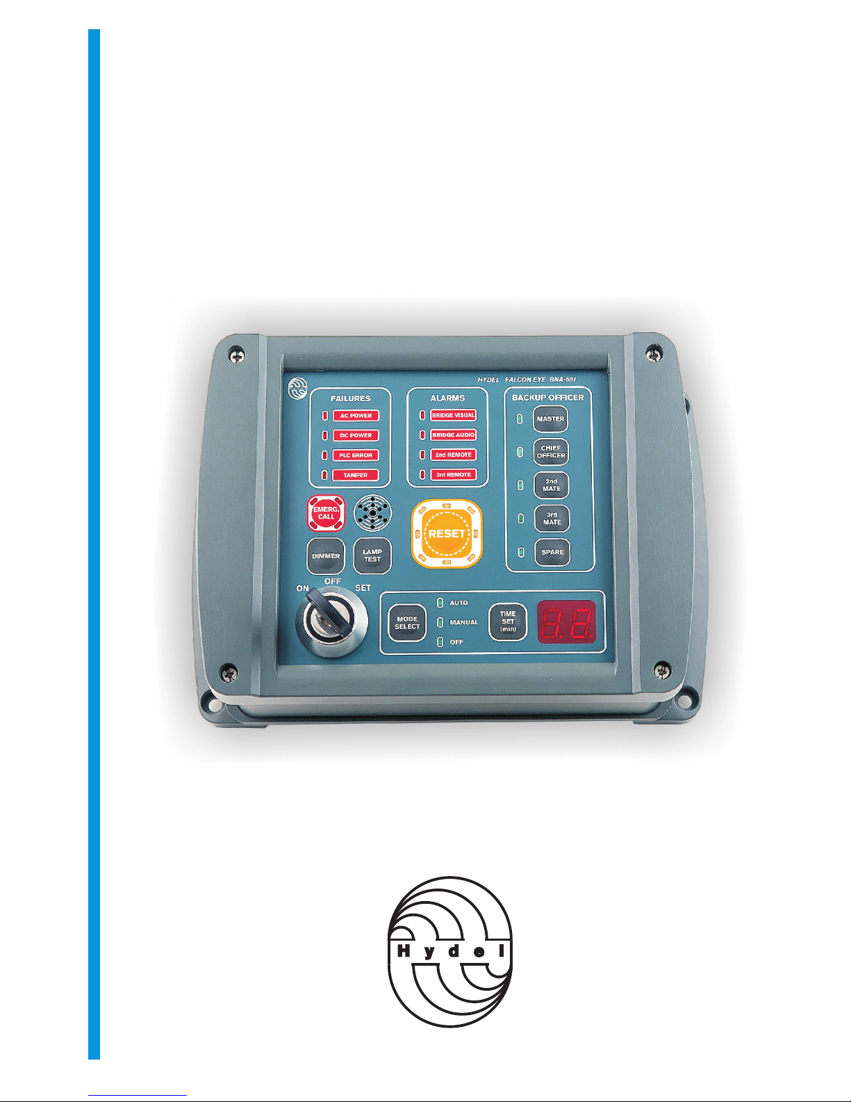
1.2.3 Control Panel (dwg. 04)
Control Panel must be positioned in a bridge location providing proper lookout. It can be flush mounted or
bulkhead mounted.
Bulkhead mount
Use the template on page 31 to mark hole positions. Drill the appropriate pilot holes. Unscrew the four screws
(page 23). Remove the front cover of the unit. Mount the mounting base to the bulkhead using self tapping
screws. Insert the RS485 cable through the cable gland . Make the connections to the screw terminals
according to interconnection diagram (dwg.11). Mount the front cover and tighten the retaining screws. Tighten
the cable gland.
Flush Mount
Use the template on page 32 to mark the appropriate cutout and mounting hole positions. Unscrew the four
screws (page 23). Remove the mounting base of the unit. Attach RS485 cable to the screw terminals according
to interconnection diagram (dwg.11) and secure it with cable ties. Mount the unit with self tapping screws.
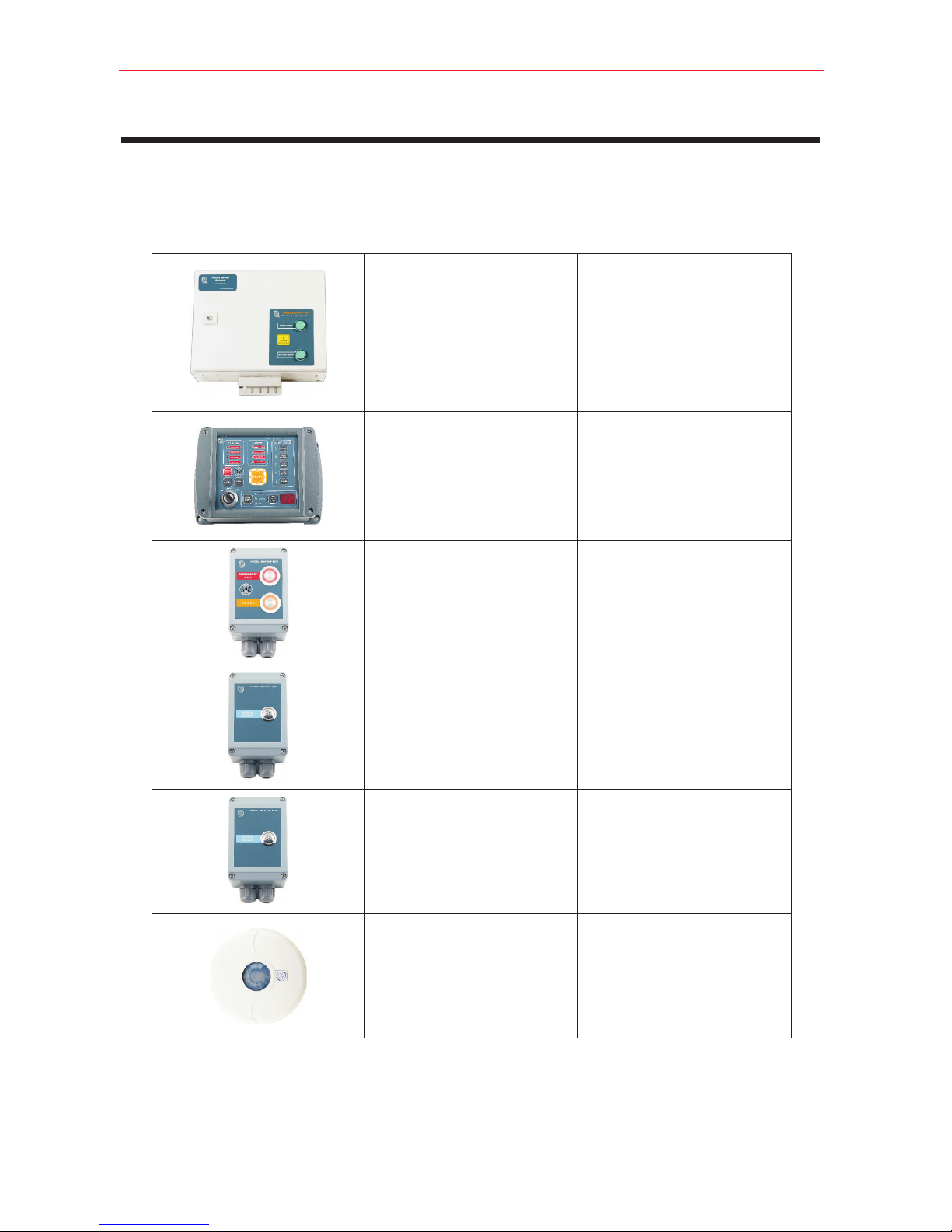
1.2.4 PIR/MW Detectors (dwg. 04)
o
PIR/MW detectors are 360 devices and must be installed on the ceiling of the bridge. They must be mounted so
as to cover all positions where the OOW might reasonably be, that offer proper lookout. Refer to page 29 for
coverage diagram. Avoid all obstructions and place the detectors away from heat generating devices,
fluorescence lights and other possible interference sources.
1.2.5 Bridge Reset and Alarm Units (dwg. 05, 06)
Bridge Reset and Alarm Units shall be easily accessible from the conning position, the workstation for
navigating and maneuvering, and the workstation for monitoring and the bridge wings. The first stage audible
alarm shall be audible from all operational positions on the bridge where the OOW may reasonably be expected
to be stationed. The visual alarm shall be visible from all operational positions on the bridge where the OOW
may reasonably be expected to be stationed.
To mount the unit remove the front cover loosening the four retaining screws (see page 24). Secure the
mounting base to the bulkhead using self tapping screws. Insert the signal cables to the cable glands.
Make the connections according to interconnection diagram (dwg.11). Replace the front cover and tighten the
four retaining screws. Tighten the cable glands.
1.2.6 Cabin and Messroom Alarm Units. (dwg. 07, 08, 09)
Cabin Alarm Units must be located to the Master’s and backup officers cabins at positions allowing unobstructed
sound transmission.
Messroom Alarm Units must be mounted to locations that allow the alerting of as many as possible of the crew.
To mount the unit remove the front cover loosening the four retaining screws (see page 26). Secure the
mounting base to the bulkhead using self tapping screws. Insert the signal cables to the cable glands. Make the
connections according to interconnection diagram (dwg.11). Replace the front cover and tighten the four
retaining screws. Tighten the cable glands.
Page 10
FALCON EYE BNA501 BNWAS
Revision A 8/2011