Teledyne Lecroy Frontline X500 User manual

Introduction
Use this document for installing a Frontline X500 Battery Pack as an external power source for the Frontline X500 protocol
analyzer. Once installed, refer to the X500 Quick Start Guide on how to use the X500 protocol analyzer. Detailed hardware
and software information is contained in the Wireless Protocol Suite Hardware and Software User Manual. The manual is
also available on FTE.com.
Components
Inspect the received shipping container for any damage. Unpack the container and account for each of the system
components listed on the accompanying packing list. Visually inspect each component for any damage. In the event of
damage, notify Teledyne LeCroy. Retain all shipping materials for shipper's inspection. The X500 battery does not contain
any user serviceable items. Any repairs and maintenance must be performed by a service technician that has been trained
and approved by Teledyne LeCroy.
The analyzer package includes the following components in addition to the X500 battery pack:
Before installing the battery pack on the X500, it is highly recommended to fully charge it.To do so, connect the power
adapter to the battery charging adapter. The LED turns red indicating the adapter is powered correctly. Then connect the
battery charging adapter to the battery pack. The LED indicator on the charging adapter starts blinking blue. When it's fully
charged, the LED turns solid green. Proceed to the installation section below.
Qty Description
1 15V 8A power supply
1 Battery charging adapter for standalone charging
Frontline X500TM Battery
Installation Guide
1
2

3Battery Installation
The Frontline X500 has an external battery pack option that allows you to extend the range of the analyzer to include
locations without easy access to external power sources. The battery pack can be connected to the X500 to operate solely
on battery power for about two hours. The battery is charged with an external charging adapter (provided by Teledyne
LeCroy) or can be charged when installed with the X500 and connected to an external power source.
To install a battery pack, follow the steps below:
Figure 1 – Frontline X500 battery
1. Turn off power and disconnect the external power source. Ensure that the power switch in the back of the X500 battery
pack is off.
Figure 2 - Frontline X500 battery switch in the off state
2. Open the battery compartment by removing the two screws on the underside of the unit. Take the cover off.

Figure 3 - Frontline X500 showing battery connection compartment
3. Remove the four side screws (two on each side of the unit) to allow connecting the four thumb screws on the battery
pack
Figure 4 - Frontline X500 showing screws on the sides
4. Place the Frontline X500 in the battery connection slot and tighten the four thumbscrews to securely connect the battery
pack to the X500.

Figure 5 - Frontline X500 and Battery installed
5. After installing the battery, apply power to the X500 by turning the switch to ON. Check the battery charge on the front
panel battery charge LEDs.
Figure 6- X500 Battery in the ON state
6. If a charge is necessary, connect the external power source to the X500 until the battery is fully charged. Once you connect
the power source the LEDs will start blinking based on the charge level.

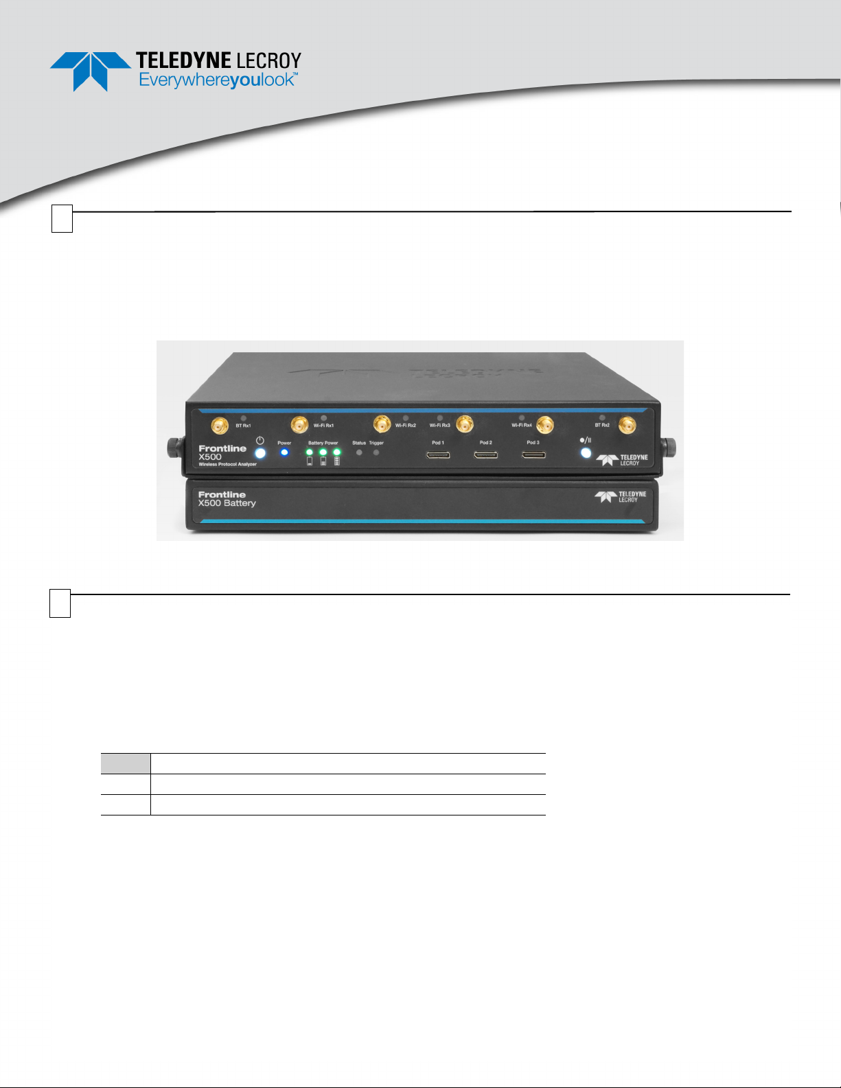
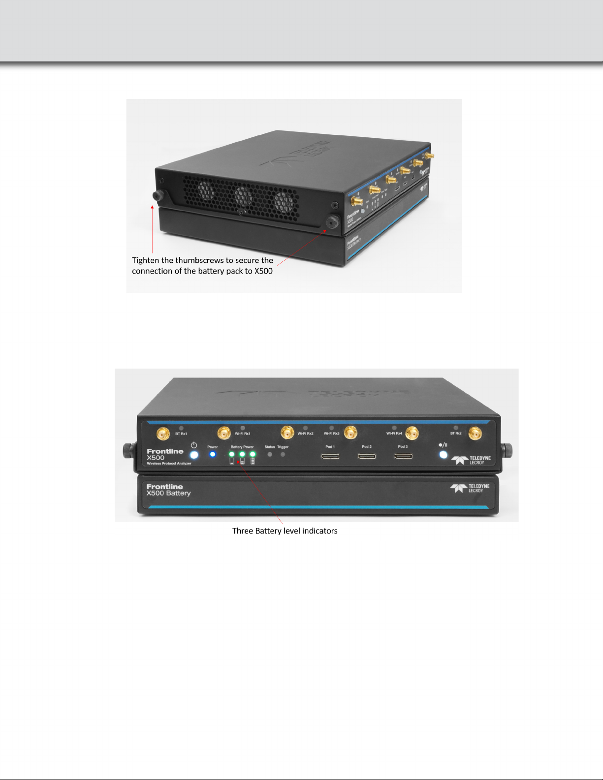
Table 1: X500 Battery Power Status Indicators
General Precautions
Handling
• Avoid shorting the battery.
• Do not immerse in water.
• Do not disassemble or deform the battery.
• Do not expose to or dispose of the battery in fire.
• Avoid excessive physical shock or vibration.
• Keep out of the reach of children.
• Never use a battery that appears to have suffered abuse.
Charge & Discharge
• Battery should be charged when docked on X500 or power adapter provided by Teledyne.
• Never use a modified or damaged charger.
• Specified product use only.
Storage
• Store in a cool, dry, and well-ventilated area.
Disposal
• Regulations vary for different countries. Dispose of in accordance with local regulations.
Indicator Color State Status Indicated
Battery
Level 1
None Off Battery not present OR
Battery not charged
Green
Green
Constant Battery discharging. Capacity 20% - 45%.
Slow Flash Battery charging. Capacity 20% - 45%.
Yellow Slow Flash Battery charging. Capacity <20%.
Fast Flash Battery discharging. Capacity <20%.
Battery
Level 2
None Off Battery not present OR
Battery <45% capacity, and not charging.
Green
Green
Constant Battery discharging. Capacity 45% - 70%.
Flash Battery charging. Capacity 45% - 70%.
Battery
Level 3
None Off Battery not present OR
Battery <70% capacity, and not charging.
Green
Green
Constant Battery discharging. Capacity 70% - 100%.
Flash Battery charging. Capacity 70% - 100%.
4

Trademarks and Servicemarks
Teledyne LeCroy, Wireless Protocol Suite, Frontline and X500 Analyzer are trademarks of Teledyne LeCroy. Microsoft and Windows are registered
trademarks of Microsoft Inc. The Bluetooth SIG owns the Bluetooth word mark and logos, and use of such marks is under license. All other
trademarks are property of their respective companies.
Changes
Product specifications are subject to change without notice.
Teledyne LeCroy reserves the right to revise the information in this document without notice or penalty.
Teledyne LeCroy Customer Support
Periodically check the Teledyne LeCroy Protocol Solutions Group web site for software updates and other support related to this product.
Web: http://www.fte.com/products/default.aspx
Sales: Frontline_OnlineSales@Teledyne.com
Support: Frontline_Techsupport@Teledyne.com
© 2021 Teledyne LeCroy, Inc. All rights reserved.
Part Number: 934244-00 Rev A
This document may be printed and reproduced without additional permission, but all copies should contain this copyright notice.
Specifications
• Type: Rechargeable Smart Lithium Ion Battery Pack
• Assembly: External, user removable
• Dimensions: 310.39 x 241.3 x 56.39 mm (12.22'' x 9.5'' x 2.22'')
• Temperature Operating: 32° F to 113° F (0° C to 45° C) for charging and -4° F to 140° F(-20° C to 60° C) for discharging
• Power Capacity: 90 WAh
• Operating time: ~2 hours (varies based on RF activity)
5
Table of contents