Teledyne Tekmar Lumin 15-2500-074 User manual


Copyright © 2016 Teledyne Technologies Incorporated
All rights reserved. Reproduction, adaptation, or translation without permission is prohibited, except as allowed under copy-
right laws. Printed in the U.S.A.
Updated Information
The information contained in this document is subject to change without notice.
Trademarks
The companies indicated own the following trademarks:
Teledyne Tekmar
4736 Socialville Foster Road
Mason, OH 45040 U.S.A
www.teledynetekmar.com
Toll Free: 800-543-4461
Sales/Support: 800-874-2004
Main: 513-229-7000
Fax: 513-229-7050
Tekmar ..........................................Teledyne Instruments, Inc.
All other brands or product names are trademarks or registered trademarks of their respective owners.

Table of Contents
Lumin User Manual 1 - 1
Lumin User Manual
Table of Contents
Preface
P.1 Warranty . . . . . . . . . . . . . . . . . . . . . . . . . . . . . . . . . . . . . . . . . . . . . . . . . . P-1
P.2 Teledyne Tekmar Customer Support Center. . . . . . . . . . . . . . . . . . . . . . . P-1
P.3 Essential Instructions. . . . . . . . . . . . . . . . . . . . . . . . . . . . . . . . . . . . . . . . . P-1
P.4 Notations and Hazard Severity Levels. . . . . . . . . . . . . . . . . . . . . . . . . . . . P-2
P.5 Lumin Safety Symbols. . . . . . . . . . . . . . . . . . . . . . . . . . . . . . . . . . . . . . . . P-3
P.6 Lumin Safety Labels . . . . . . . . . . . . . . . . . . . . . . . . . . . . . . . . . . . . . . . . . P-5
P.7 Working Safely. . . . . . . . . . . . . . . . . . . . . . . . . . . . . . . . . . . . . . . . . . . . . . P-6
Chapter 1: Introduction
1.1 Purge and Trap Background . . . . . . . . . . . . . . . . . . . . . . . . . . . . . . . . . . . 1-1
1.1.1 Purge and Trap Fundamentals. . . . . . . . . . . . . . . . . . . . . . . . . . . . . 1-1
1.1.2 Brief History . . . . . . . . . . . . . . . . . . . . . . . . . . . . . . . . . . . . . . . . . . . 1-2
1.2 Purge and Trap Operation Overview . . . . . . . . . . . . . . . . . . . . . . . . . . . . . 1-2
1.2.1 Trapping, Adsorption and Desorption. . . . . . . . . . . . . . . . . . . . . . . . 1-3
1.3 Lumin Specifications . . . . . . . . . . . . . . . . . . . . . . . . . . . . . . . . . . . . . . . . . 1-4
1.4 Lumin Component Overview . . . . . . . . . . . . . . . . . . . . . . . . . . . . . . . . . . . 1-7
1.4.1 Sample Mount and Sparger . . . . . . . . . . . . . . . . . . . . . . . . . . . . . . . 1-8
1.4.2 Guardian™ Foam Sensor & Eliminator (Optional) . . . . . . . . . . . . . . 1-8
1.4.3 Status Light. . . . . . . . . . . . . . . . . . . . . . . . . . . . . . . . . . . . . . . . . . . . 1-9
1.4.4 Sample Purge Gas Inlet . . . . . . . . . . . . . . . . . . . . . . . . . . . . . . . . . . 1-9
1.4.5 Mass Flow Controller (MFC). . . . . . . . . . . . . . . . . . . . . . . . . . . . . . 1-10
1.4.6 Sample Pathway. . . . . . . . . . . . . . . . . . . . . . . . . . . . . . . . . . . . . . . 1-10
1.4.7 Analytical Trap . . . . . . . . . . . . . . . . . . . . . . . . . . . . . . . . . . . . . . . . 1-11
1.4.8 Moisture Control System (MCS). . . . . . . . . . . . . . . . . . . . . . . . . . . 1-11
1.4.9 Carrier Gas Inlet Line/Heated Sample Transfer Line . . . . . . . . . . . 1-12
1.4.10 Valving . . . . . . . . . . . . . . . . . . . . . . . . . . . . . . . . . . . . . . . . . . . . . 1-13
1.4.11 24VDC Power Supply. . . . . . . . . . . . . . . . . . . . . . . . . . . . . . . . . . 1-15
1.4.12 5VDC Power Supply. . . . . . . . . . . . . . . . . . . . . . . . . . . . . . . . . . . 1-15
1.4.13 Multi-Channel Temperature Control Board. . . . . . . . . . . . . . . . . . 1-16
1.4.14 CPU Communication Board (Master Board). . . . . . . . . . . . . . . . . 1-17
1.4.15 DC Valve Control Board . . . . . . . . . . . . . . . . . . . . . . . . . . . . . . . . 1-18
1.5 Optional Autosampler. . . . . . . . . . . . . . . . . . . . . . . . . . . . . . . . . . . . . . . . 1-19
1.6 Optional Guardian™ Foam Sensor and Foam Eliminator . . . . . . . . . . . . 1-19
Chapter 2: Installation and Setup
2.1 Pre-Installation. . . . . . . . . . . . . . . . . . . . . . . . . . . . . . . . . . . . . . . . . . . . . . 2-1
2.1.1 Overview. . . . . . . . . . . . . . . . . . . . . . . . . . . . . . . . . . . . . . . . . . . . . . 2-1
2.1.2 Operating Environment. . . . . . . . . . . . . . . . . . . . . . . . . . . . . . . . . . . 2-1
2.1.3 Work Surface Requirements. . . . . . . . . . . . . . . . . . . . . . . . . . . . . . . 2-1
2.1.4 Electrical Requirements . . . . . . . . . . . . . . . . . . . . . . . . . . . . . . . . . . 2-2
2.1.5 Gas Supply Requirements . . . . . . . . . . . . . . . . . . . . . . . . . . . . . . . . 2-2
2.1.6 Minimum Computer Requirements. . . . . . . . . . . . . . . . . . . . . . . . . . 2-4
2.1.7 Required Tools and Supplies for Installation . . . . . . . . . . . . . . . . . . 2-4
2.2 Unpacking the Lumin . . . . . . . . . . . . . . . . . . . . . . . . . . . . . . . . . . . . . . . . . 2-5
2.3 Installation Kit Box . . . . . . . . . . . . . . . . . . . . . . . . . . . . . . . . . . . . . . . . . . . 2-5
2.4 Concentrator Overview . . . . . . . . . . . . . . . . . . . . . . . . . . . . . . . . . . . . . . . 2-6
2.5 Electrical and Data Connections . . . . . . . . . . . . . . . . . . . . . . . . . . . . . . . . 2-9
2.5.1 AC Power Cord. . . . . . . . . . . . . . . . . . . . . . . . . . . . . . . . . . . . . . . . . 2-9

Table of Contents
Lumin User Manual
1 - 2
2.5.2 Connect the USB Interface Cable. . . . . . . . . . . . . . . . . . . . . . . . . . 2-10
2.5.3 GC I/O (Input/Output) Connection. . . . . . . . . . . . . . . . . . . . . . . . . . 2-10
2.6 Connecting the Lumin Sample Purge Gas Supply . . . . . . . . . . . . . . . . . . 2-11
2.7 Lumin Carrier Gas and Sample Transfer Line Connection to the Gas
Chromatograph (GC) . . . . . . . . . . . . . . . . . . . . . . . . . . . . . . . . . . . . . . . . 2-12
2.8 Routing the Drain Tubing . . . . . . . . . . . . . . . . . . . . . . . . . . . . . . . . . . . . . 2-14
2.9 Install Lumin TekLink Software. . . . . . . . . . . . . . . . . . . . . . . . . . . . . . . . . 2-15
2.9.1 Microsoft®SQL Server Installation . . . . . . . . . . . . . . . . . . . . . . . . . 2-16
2.9.2 .Net Installation . . . . . . . . . . . . . . . . . . . . . . . . . . . . . . . . . . . . . . . . 2-17
2.10 USB Driver Installation . . . . . . . . . . . . . . . . . . . . . . . . . . . . . . . . . . . . . . 2-17
2.11 Create an Instrument Profile. . . . . . . . . . . . . . . . . . . . . . . . . . . . . . . . . . 2-18
2.12 Autosampler Setup and Connection. . . . . . . . . . . . . . . . . . . . . . . . . . . . 2-22
2.12.1 Communication Cable Connection . . . . . . . . . . . . . . . . . . . . . . . . 2-22
2.12.2 Aqueous Transfer Line Installation . . . . . . . . . . . . . . . . . . . . . . . . 2-22
2.12.3 Autosampler Method Configuration. . . . . . . . . . . . . . . . . . . . . . . . 2-23
2.13 Guardian™ Foam Sensor and Foam Eliminator (Optional) . . . . . . . . . . 2-23
2.13.1 Configuring the Guardian™ Foam Sensor & Eliminator . . . . . . . . 2-25
Chapter 3: Lumin TekLink Software Overview
3.1 About Lumin TekLink Software. . . . . . . . . . . . . . . . . . . . . . . . . . . . . . . . . . 3-1
3.2 The Lumin TekLink Software Environment. . . . . . . . . . . . . . . . . . . . . . . . . 3-1
3.2.1 Touchscreen Capability. . . . . . . . . . . . . . . . . . . . . . . . . . . . . . . . . . . 3-1
3.2.2 “Pinnable” Screens . . . . . . . . . . . . . . . . . . . . . . . . . . . . . . . . . . . . . . 3-2
3.2.3 Title Bar. . . . . . . . . . . . . . . . . . . . . . . . . . . . . . . . . . . . . . . . . . . . . . . 3-2
3.2.4 Open, Save, Load, and Print Buttons . . . . . . . . . . . . . . . . . . . . . . . . 3-3
3.2.5 Instrument Control Buttons . . . . . . . . . . . . . . . . . . . . . . . . . . . . . . . . 3-4
3.2.6 Delete at Next Archive Check-Box . . . . . . . . . . . . . . . . . . . . . . . . . . 3-4
3.3 Primary Screens. . . . . . . . . . . . . . . . . . . . . . . . . . . . . . . . . . . . . . . . . . . . . 3-5
3.3.1 The Home Screen. . . . . . . . . . . . . . . . . . . . . . . . . . . . . . . . . . . . . . . 3-5
3.3.2 Instrument Status Panel . . . . . . . . . . . . . . . . . . . . . . . . . . . . . . . . . . 3-6
3.4 Methods Screen . . . . . . . . . . . . . . . . . . . . . . . . . . . . . . . . . . . . . . . . . . . . . 3-7
3.4.1 Standby Tab . . . . . . . . . . . . . . . . . . . . . . . . . . . . . . . . . . . . . . . . . . . 3-7
3.4.2 Purge Tab . . . . . . . . . . . . . . . . . . . . . . . . . . . . . . . . . . . . . . . . . . . . . 3-8
3.4.3 Desorb Tab . . . . . . . . . . . . . . . . . . . . . . . . . . . . . . . . . . . . . . . . . . . 3-10
3.4.4 Bake Tab. . . . . . . . . . . . . . . . . . . . . . . . . . . . . . . . . . . . . . . . . . . . . 3-11
3.4.5 AQUATek 100 Tab . . . . . . . . . . . . . . . . . . . . . . . . . . . . . . . . . . . . . 3-12
3.5 Schedules Screen. . . . . . . . . . . . . . . . . . . . . . . . . . . . . . . . . . . . . . . . . . . 3-14
3.6 Tools Screen. . . . . . . . . . . . . . . . . . . . . . . . . . . . . . . . . . . . . . . . . . . . . . . 3-15
3.6.1 Prime Menu. . . . . . . . . . . . . . . . . . . . . . . . . . . . . . . . . . . . . . . . . . . 3-16
3.6.2 Commands Menu . . . . . . . . . . . . . . . . . . . . . . . . . . . . . . . . . . . . . . 3-16
3.6.3 System Menu . . . . . . . . . . . . . . . . . . . . . . . . . . . . . . . . . . . . . . . . . 3-18
3.6.4 About. . . . . . . . . . . . . . . . . . . . . . . . . . . . . . . . . . . . . . . . . . . . . . . . 3-28
3.6.5 Diagnostics . . . . . . . . . . . . . . . . . . . . . . . . . . . . . . . . . . . . . . . . . . . 3-28
3.7 Create an Instrument Profile. . . . . . . . . . . . . . . . . . . . . . . . . . . . . . . . . . . 3-32
3.8 Connect to an Instrument Profile . . . . . . . . . . . . . . . . . . . . . . . . . . . . . . . 3-35
3.9 Deactivate an Instrument Profile. . . . . . . . . . . . . . . . . . . . . . . . . . . . . . . . 3-36
3.10 Creating a Method . . . . . . . . . . . . . . . . . . . . . . . . . . . . . . . . . . . . . . . . . 3-37
3.10.1 Save the Method. . . . . . . . . . . . . . . . . . . . . . . . . . . . . . . . . . . . . . 3-38
3.11 Open a Method. . . . . . . . . . . . . . . . . . . . . . . . . . . . . . . . . . . . . . . . . . . . 3-39
3.11.1 Print a Method. . . . . . . . . . . . . . . . . . . . . . . . . . . . . . . . . . . . . . . . 3-41
3.12 Creating a Schedule. . . . . . . . . . . . . . . . . . . . . . . . . . . . . . . . . . . . . . . . 3-42
3.12.1 Save Schedule . . . . . . . . . . . . . . . . . . . . . . . . . . . . . . . . . . . . . . . 3-45
3.12.2 Load (Run) the Schedule . . . . . . . . . . . . . . . . . . . . . . . . . . . . . . . 3-46
3.12.3 Abort a Sample or Schedule. . . . . . . . . . . . . . . . . . . . . . . . . . . . . 3-47

Table of Contents
Lumin User Manual 1 - 3
Chapter 4: Instrument Operations
4.1 Concentrator Mode Descriptions . . . . . . . . . . . . . . . . . . . . . . . . . . . . . . . . 4-1
4.2 Lumin Valve Output Chart . . . . . . . . . . . . . . . . . . . . . . . . . . . . . . . . . . . . . 4-3
4.3 Lumin with AQUATek 100 Valve Output Chart . . . . . . . . . . . . . . . . . . . . . 4-6
4.4 Optimization. . . . . . . . . . . . . . . . . . . . . . . . . . . . . . . . . . . . . . . . . . . . . . . 4-10
4.4.1 Temperatures . . . . . . . . . . . . . . . . . . . . . . . . . . . . . . . . . . . . . . . . . 4-10
4.4.2 Standby Mode. . . . . . . . . . . . . . . . . . . . . . . . . . . . . . . . . . . . . . . . . 4-10
4.4.3 Purge Ready Mode. . . . . . . . . . . . . . . . . . . . . . . . . . . . . . . . . . . . . 4-11
4.4.4 Pre-Purge Mode . . . . . . . . . . . . . . . . . . . . . . . . . . . . . . . . . . . . . . . 4-11
4.4.5 Sample Temperature and Pre-Heat Mode . . . . . . . . . . . . . . . . . . . 4-11
4.4.6 Purge Mode . . . . . . . . . . . . . . . . . . . . . . . . . . . . . . . . . . . . . . . . . . 4-12
4.4.7 Dry Purge Mode . . . . . . . . . . . . . . . . . . . . . . . . . . . . . . . . . . . . . . . 4-12
4.4.8 Desorb Ready Mode. . . . . . . . . . . . . . . . . . . . . . . . . . . . . . . . . . . . 4-12
4.4.9 Desorb Pre-Heat Mode. . . . . . . . . . . . . . . . . . . . . . . . . . . . . . . . . . 4-12
4.4.10 Desorb Mode . . . . . . . . . . . . . . . . . . . . . . . . . . . . . . . . . . . . . . . . 4-13
4.4.11 Bake Mode . . . . . . . . . . . . . . . . . . . . . . . . . . . . . . . . . . . . . . . . . . 4-13
4.4.12 Analytical Trap Recommended Conditioning Settings . . . . . . . . . 4-13
4.4.13 Analytical Trap Recommended Operating Conditions . . . . . . . . . 4-14
Chapter 5: Maintenance and Troubleshooting
5.1 Replacing Parts . . . . . . . . . . . . . . . . . . . . . . . . . . . . . . . . . . . . . . . . . . . . . 5-1
5.2 Preventative Maintenance Checks. . . . . . . . . . . . . . . . . . . . . . . . . . . . . . . 5-2
5.2.1 Daily Maintenance Checks. . . . . . . . . . . . . . . . . . . . . . . . . . . . . . . . 5-2
5.2.2 Weekly Maintenance Checks . . . . . . . . . . . . . . . . . . . . . . . . . . . . . . 5-2
5.2.3 Monthly Maintenance Checks. . . . . . . . . . . . . . . . . . . . . . . . . . . . . . 5-2
5.3 Preventative Maintenance Chart . . . . . . . . . . . . . . . . . . . . . . . . . . . . . . . . 5-3
5.4 GC/IO Cable and GC Type Reference. . . . . . . . . . . . . . . . . . . . . . . . . . . . 5-4
5.5 Instrument Access Panels . . . . . . . . . . . . . . . . . . . . . . . . . . . . . . . . . . . . . 5-5
5.6 Plumbing Overview . . . . . . . . . . . . . . . . . . . . . . . . . . . . . . . . . . . . . . . . . . 5-8
5.7 Electrical Overview. . . . . . . . . . . . . . . . . . . . . . . . . . . . . . . . . . . . . . . . . . 5-10
5.7.1 Power Supplies. . . . . . . . . . . . . . . . . . . . . . . . . . . . . . . . . . . . . . . . 5-10
5.7.2 Printed Circuit Boards. . . . . . . . . . . . . . . . . . . . . . . . . . . . . . . . . . . 5-11
5.8 Glassware Cleaning Procedures . . . . . . . . . . . . . . . . . . . . . . . . . . . . . . . 5-12
5.9 Sparger Replacement . . . . . . . . . . . . . . . . . . . . . . . . . . . . . . . . . . . . . . . 5-13
5.10 Analytical Trap Replacement. . . . . . . . . . . . . . . . . . . . . . . . . . . . . . . . . 5-15
5.11 Analytical Trap Conditioning . . . . . . . . . . . . . . . . . . . . . . . . . . . . . . . . . 5-18
5.12 Analytical Trap Heater Jacket . . . . . . . . . . . . . . . . . . . . . . . . . . . . . . . . 5-19
5.13 Analytical Trap Cooling Fan. . . . . . . . . . . . . . . . . . . . . . . . . . . . . . . . . . 5-21
5.14 MCS Cooling Fan. . . . . . . . . . . . . . . . . . . . . . . . . . . . . . . . . . . . . . . . . . 5-25
5.15 Pencil Filter Replacement . . . . . . . . . . . . . . . . . . . . . . . . . . . . . . . . . . . 5-28
5.16 Check Valve. . . . . . . . . . . . . . . . . . . . . . . . . . . . . . . . . . . . . . . . . . . . . . 5-29
5.17 Valve Manifold Replacement . . . . . . . . . . . . . . . . . . . . . . . . . . . . . . . . . 5-30
5.18 Valve Replacement . . . . . . . . . . . . . . . . . . . . . . . . . . . . . . . . . . . . . . . . 5-31
5.19 Moisture Control System (MCS) . . . . . . . . . . . . . . . . . . . . . . . . . . . . . . 5-33
5.20 Mass Flow Controller (MFC) . . . . . . . . . . . . . . . . . . . . . . . . . . . . . . . . . 5-35
5.21 6-Port Valve . . . . . . . . . . . . . . . . . . . . . . . . . . . . . . . . . . . . . . . . . . . . . . 5-36
5.22 Power Entry Module (PEM) Fuse Replacement . . . . . . . . . . . . . . . . . . 5-37
5.23 Multi-Channel Temperature Control Board Fuse Replacement. . . . . . . 5-40
5.23.1 Main Fuse. . . . . . . . . . . . . . . . . . . . . . . . . . . . . . . . . . . . . . . . . . . 5-40
5.23.2 Heater Output Fuses . . . . . . . . . . . . . . . . . . . . . . . . . . . . . . . . . . 5-42
5.24 Multi-Channel Temperature Control PCB Replacement . . . . . . . . . . . . 5-44
5.25 CPU Communication (Master) PCB Replacement. . . . . . . . . . . . . . . . . 5-47
5.26 DC Valve Control PCB Replacement. . . . . . . . . . . . . . . . . . . . . . . . . . . 5-50
5.27 5VDC Power Supply Replacement . . . . . . . . . . . . . . . . . . . . . . . . . . . . 5-53
5.28 24VDC Power Supply Replacement . . . . . . . . . . . . . . . . . . . . . . . . . . . 5-55

Table of Contents
Lumin User Manual
1 - 4
5.29 Upgrade Firmware . . . . . . . . . . . . . . . . . . . . . . . . . . . . . . . . . . . . . . . . . 5-56
5.29.1 Download Firmware . . . . . . . . . . . . . . . . . . . . . . . . . . . . . . . . . . . 5-56
5.29.2 Upgrade Board Firmware . . . . . . . . . . . . . . . . . . . . . . . . . . . . . . . 5-56
5.30 Upgrade Software. . . . . . . . . . . . . . . . . . . . . . . . . . . . . . . . . . . . . . . . . . 5-56
5.31 Troubleshooting . . . . . . . . . . . . . . . . . . . . . . . . . . . . . . . . . . . . . . . . . . . 5-57
5.31.1 Benchmark Test . . . . . . . . . . . . . . . . . . . . . . . . . . . . . . . . . . . . . . 5-57
5.31.2 Initial Leak Check . . . . . . . . . . . . . . . . . . . . . . . . . . . . . . . . . . . . . 5-59
5.31.3 Advanced Leak Check Guidelines . . . . . . . . . . . . . . . . . . . . . . . . 5-61
5.31.4 Advanced Leak Checking Flow Chart. . . . . . . . . . . . . . . . . . . . . . 5-64
5.31.5 No Power Flow Chart . . . . . . . . . . . . . . . . . . . . . . . . . . . . . . . . . . 5-65
5.31.6 Top-of-Trap (TOT) Injection Port. . . . . . . . . . . . . . . . . . . . . . . . . . 5-66
5.31.7 No Response Flow Chart . . . . . . . . . . . . . . . . . . . . . . . . . . . . . . . 5-70
5.31.8 Low Response Flow Chart . . . . . . . . . . . . . . . . . . . . . . . . . . . . . . 5-71
5.31.9 Carryover Contamination Flow Chart. . . . . . . . . . . . . . . . . . . . . . 5-72
5.32 Returning the Lumin . . . . . . . . . . . . . . . . . . . . . . . . . . . . . . . . . . . . . . . . 5-72
5.33 Unit and Parts Disposal . . . . . . . . . . . . . . . . . . . . . . . . . . . . . . . . . . . . . 5-73
5.34 Technical Assistance . . . . . . . . . . . . . . . . . . . . . . . . . . . . . . . . . . . . . . . 5-73
5.34.1 Teledyne Tekmar Customer Support . . . . . . . . . . . . . . . . . . . . . . 5-73
Appendix A: Diagrams
A.1 Lumin Electrical Schematic . . . . . . . . . . . . . . . . . . . . . . . . . . . . . . . . . . . . A-2
A.2 Lumin Plumbing Diagram. . . . . . . . . . . . . . . . . . . . . . . . . . . . . . . . . . . . . . A-3
A.3 Lumin Flow Diagrams. . . . . . . . . . . . . . . . . . . . . . . . . . . . . . . . . . . . . . . . . A-4
A.3.1 Lumin - Basic Flow Diagram. . . . . . . . . . . . . . . . . . . . . . . . . . . . . . .A-4
A.3.2 Lumin - Standby Dry Purge Flow Diagram. . . . . . . . . . . . . . . . . . . .A-5
A.3.3 Lumin Purge Flow Diagram . . . . . . . . . . . . . . . . . . . . . . . . . . . . . . .A-6
A.3.4 Lumin Desorb Flow Diagram . . . . . . . . . . . . . . . . . . . . . . . . . . . . . .A-7
A.3.5 Lumin Bake Flow Diagram . . . . . . . . . . . . . . . . . . . . . . . . . . . . . . . .A-8
A.4 Lumin With Guardian™ Foam Sensor (GFS) & Eliminator Flow DiagramsA-9
A.4.1 Lumin With GFS & Eliminator - Basic Flow Diagram . . . . . . . . . . . .A-9
A.4.2 Lumin With GFS & Eliminator - Standby/Dry Purge Flow Diagram A-10
A.4.3 Lumin With GFS & Eliminator - Eliminator Ready Flow Diagram . .A-11
A.4.4 Lumin With GFS & Eliminator - Purge Flow Diagram. . . . . . . . . . .A-12
A.4.5 Lumin With GFS & Eliminator - Add Defoamer Flow Diagram . . . .A-13
A.4.6 Lumin With GFS & Eliminator - Eliminator Rinse Flow Diagram . .A-14
A.4.7 Lumin With GFS & Eliminator - Desorb Flow Diagram. . . . . . . . . .A-15
A.4.8 Lumin With GFS & Eliminator - Bake Flow Diagram . . . . . . . . . . .A-16
List of Figures
1-1 Headspace Equilibrium Diagram . . . . . . . . . . . . . . . . . . . . . . . . . . . . . . . . 1-2
1-2 Sample Mount and Sparger . . . . . . . . . . . . . . . . . . . . . . . . . . . . . . . . . . . . 1-8
1-3 Unit Status Light/Mode Indicator . . . . . . . . . . . . . . . . . . . . . . . . . . . . . . . . 1-9
1-4 Mass Flow Controller . . . . . . . . . . . . . . . . . . . . . . . . . . . . . . . . . . . . . . . . 1-10
1-5 Lumin Analytical Trap Compartment . . . . . . . . . . . . . . . . . . . . . . . . . . . . 1-11
1-6 Moisture Control System . . . . . . . . . . . . . . . . . . . . . . . . . . . . . . . . . . . . . 1-12
1-7 Carrier Gas Inlet Line and Heated Sample Transfer Line . . . . . . . . . . . . 1-12
1-8 Lumin Valve Manifold and Solenoid Valves . . . . . . . . . . . . . . . . . . . . . . . 1-13
1-9 Heated 6-Port Valve. . . . . . . . . . . . . . . . . . . . . . . . . . . . . . . . . . . . . . . . . 1-13
1-10 3-Port Sample Valve. . . . . . . . . . . . . . . . . . . . . . . . . . . . . . . . . . . . . . . . 1-14
1-11 24VDC Power Supply. . . . . . . . . . . . . . . . . . . . . . . . . . . . . . . . . . . . . . . 1-15
1-12 5VDC Power Supply. . . . . . . . . . . . . . . . . . . . . . . . . . . . . . . . . . . . . . . . 1-15
1-13 Multi-Channel Temperature Control Board. . . . . . . . . . . . . . . . . . . . . . . 1-16
1-14 Multi-Channel Temperature Control Board. . . . . . . . . . . . . . . . . . . . . . . 1-16
1-15 CPU Communication Board (Master Board) . . . . . . . . . . . . . . . . . . . . . 1-17

Table of Contents
Lumin User Manual 1 - 5
1-16 CPU Communication Board Location . . . . . . . . . . . . . . . . . . . . . . . . . . 1-17
1-17 DC Valve Control Board. . . . . . . . . . . . . . . . . . . . . . . . . . . . . . . . . . . . . 1-18
1-18 DC Valve Control Board Location . . . . . . . . . . . . . . . . . . . . . . . . . . . . . 1-18
2-1 Installation Kit Box Diagram. . . . . . . . . . . . . . . . . . . . . . . . . . . . . . . . . . . . 2-5
2-2 Front of Lumin . . . . . . . . . . . . . . . . . . . . . . . . . . . . . . . . . . . . . . . . . . . . . . 2-6
2-3 Back of Lumin . . . . . . . . . . . . . . . . . . . . . . . . . . . . . . . . . . . . . . . . . . . . . . 2-7
2-4 Right Side of Lumin . . . . . . . . . . . . . . . . . . . . . . . . . . . . . . . . . . . . . . . . . . 2-8
2-5 Left Side of the Lumin . . . . . . . . . . . . . . . . . . . . . . . . . . . . . . . . . . . . . . . . 2-8
2-6 Lumin Power Entry Module . . . . . . . . . . . . . . . . . . . . . . . . . . . . . . . . . . . . 2-9
2-7 Lumin USB Connection . . . . . . . . . . . . . . . . . . . . . . . . . . . . . . . . . . . . . . 2-10
2-8 Rear of Lumin - Sample Purge Gas Connection . . . . . . . . . . . . . . . . . . . 2-12
2-9 Connecting to the GC Carrier Gas. . . . . . . . . . . . . . . . . . . . . . . . . . . . . . 2-13
2-10 Lumin TekLink Installation Wizard. . . . . . . . . . . . . . . . . . . . . . . . . . . . . 2-15
2-11 Microsoft® SQL Server Installation Notification Message . . . . . . . . . . . 2-16
2-12 .NET Setup Installation Notification Message . . . . . . . . . . . . . . . . . . . . 2-16
2-13 Microsoft SQL Server Installation Wizard . . . . . . . . . . . . . . . . . . . . . . . 2-17
2-14 Creating an Instrument Profile. . . . . . . . . . . . . . . . . . . . . . . . . . . . . . . . 2-19
2-15 Options Tab . . . . . . . . . . . . . . . . . . . . . . . . . . . . . . . . . . . . . . . . . . . . . . 2-20
2-16 Leak Check Tab. . . . . . . . . . . . . . . . . . . . . . . . . . . . . . . . . . . . . . . . . . . 2-20
2-17 Instrument Manager - Profile Set to Default. . . . . . . . . . . . . . . . . . . . . . 2-21
2-18 Aqueous Transfer Line Access Point. . . . . . . . . . . . . . . . . . . . . . . . . . . 2-23
2-19 Configuration Dialog- Guardian™ Foam Sensor. . . . . . . . . . . . . . . . . . 2-25
3-1 On-Screen Keyboard. . . . . . . . . . . . . . . . . . . . . . . . . . . . . . . . . . . . . . . . . 3-2
3-2 Pin Function. . . . . . . . . . . . . . . . . . . . . . . . . . . . . . . . . . . . . . . . . . . . . . . . 3-2
3-3 Schedules Screen Title Bar . . . . . . . . . . . . . . . . . . . . . . . . . . . . . . . . . . . . 3-3
3-4 Open, Save, Load, and Print Buttons . . . . . . . . . . . . . . . . . . . . . . . . . . . . 3-3
3-5 Control Buttons . . . . . . . . . . . . . . . . . . . . . . . . . . . . . . . . . . . . . . . . . . . . . 3-4
3-6 Delete at Next Archive Check-Box - Schedule Screen . . . . . . . . . . . . . . . 3-4
3-7 Open Dialog Source Drop-down Menu . . . . . . . . . . . . . . . . . . . . . . . . . . . 3-5
3-8 Home Screen. . . . . . . . . . . . . . . . . . . . . . . . . . . . . . . . . . . . . . . . . . . . . . . 3-5
3-9 Instrument Status Panel. . . . . . . . . . . . . . . . . . . . . . . . . . . . . . . . . . . . . . . 3-6
3-10 Instrument Status Zone Display Options . . . . . . . . . . . . . . . . . . . . . . . . . 3-7
3-11 Methods Screen - Standby Tab. . . . . . . . . . . . . . . . . . . . . . . . . . . . . . . . 3-8
3-12 Methods Screen - Purge Tab. . . . . . . . . . . . . . . . . . . . . . . . . . . . . . . . . . 3-9
3-13 Methods Screen - Desorb Tab. . . . . . . . . . . . . . . . . . . . . . . . . . . . . . . . 3-11
3-14 Methods Screen - Bake Tab . . . . . . . . . . . . . . . . . . . . . . . . . . . . . . . . . 3-12
3-15 AQUATek 100 Tab. . . . . . . . . . . . . . . . . . . . . . . . . . . . . . . . . . . . . . . . . 3-13
3-16 Schedules Screen . . . . . . . . . . . . . . . . . . . . . . . . . . . . . . . . . . . . . . . . . 3-15
3-17 Tools Screen . . . . . . . . . . . . . . . . . . . . . . . . . . . . . . . . . . . . . . . . . . . . . 3-15
3-18 Leak Check Dialog. . . . . . . . . . . . . . . . . . . . . . . . . . . . . . . . . . . . . . . . . 3-16
3-19 Bake Dialog . . . . . . . . . . . . . . . . . . . . . . . . . . . . . . . . . . . . . . . . . . . . . . 3-17
3-20 Tools - Configuration - General Tab . . . . . . . . . . . . . . . . . . . . . . . . . . . 3-19
3-21 Tools - Configuration - Options Tab. . . . . . . . . . . . . . . . . . . . . . . . . . . . 3-20
3-22 Tools - Configuration - Leak Check Tab . . . . . . . . . . . . . . . . . . . . . . . . 3-21
3-23 Tools - Instrument Manager. . . . . . . . . . . . . . . . . . . . . . . . . . . . . . . . . . 3-22
3-24 System Properties Dialog . . . . . . . . . . . . . . . . . . . . . . . . . . . . . . . . . . . 3-22
3-25 System Properties - Email Server Tab. . . . . . . . . . . . . . . . . . . . . . . . . . 3-23
3-26 System Properties - Email Alerts Tab . . . . . . . . . . . . . . . . . . . . . . . . . . 3-24
3-27 History Filter for Email Events Dialog . . . . . . . . . . . . . . . . . . . . . . . . . . 3-25
3-28 System Properties - Data Tab . . . . . . . . . . . . . . . . . . . . . . . . . . . . . . . . 3-26
3-29 System Properties - Connection Tab. . . . . . . . . . . . . . . . . . . . . . . . . . . 3-27
3-30 System Properties - Misc Tab . . . . . . . . . . . . . . . . . . . . . . . . . . . . . . . . 3-27
3-31 About Dialog . . . . . . . . . . . . . . . . . . . . . . . . . . . . . . . . . . . . . . . . . . . . . 3-28
3-32 Diagnostics - Valves and Flows. . . . . . . . . . . . . . . . . . . . . . . . . . . . . . . 3-29
3-33 AQUATek100 Dialog . . . . . . . . . . . . . . . . . . . . . . . . . . . . . . . . . . . . . . . 3-30

Table of Contents
Lumin User Manual
1 - 6
3-34 History Form - Instrument History. . . . . . . . . . . . . . . . . . . . . . . . . . . . . . 3-30
3-35 History Form Filter - Instrument History . . . . . . . . . . . . . . . . . . . . . . . . . 3-31
3-36 Upgrade Firmware Dialog. . . . . . . . . . . . . . . . . . . . . . . . . . . . . . . . . . . . 3-31
3-37 Creating an Instrument Profile . . . . . . . . . . . . . . . . . . . . . . . . . . . . . . . . 3-33
3-38 Options Tab . . . . . . . . . . . . . . . . . . . . . . . . . . . . . . . . . . . . . . . . . . . . . . 3-34
3-39 Leak Check Tab . . . . . . . . . . . . . . . . . . . . . . . . . . . . . . . . . . . . . . . . . . . 3-34
3-40 Instrument Manager . . . . . . . . . . . . . . . . . . . . . . . . . . . . . . . . . . . . . . . . 3-36
3-41 Methods Screen . . . . . . . . . . . . . . . . . . . . . . . . . . . . . . . . . . . . . . . . . . . 3-37
3-42 Save Method As Dialog . . . . . . . . . . . . . . . . . . . . . . . . . . . . . . . . . . . . . 3-38
3-43 New method Saved - Name in Title Bar. . . . . . . . . . . . . . . . . . . . . . . . . 3-39
3-44 Methods Screen . . . . . . . . . . . . . . . . . . . . . . . . . . . . . . . . . . . . . . . . . . . 3-40
3-45 Open Method Dialog. . . . . . . . . . . . . . . . . . . . . . . . . . . . . . . . . . . . . . . . 3-40
3-46 25 mL Method Open. . . . . . . . . . . . . . . . . . . . . . . . . . . . . . . . . . . . . . . . 3-41
3-47 Method Print Dialog . . . . . . . . . . . . . . . . . . . . . . . . . . . . . . . . . . . . . . . . 3-41
3-48 Blank Schedule. . . . . . . . . . . . . . . . . . . . . . . . . . . . . . . . . . . . . . . . . . . . 3-42
3-49 Zero in Vial Column Becomes Blank . . . . . . . . . . . . . . . . . . . . . . . . . . . 3-43
3-50 Standards Drop-Down . . . . . . . . . . . . . . . . . . . . . . . . . . . . . . . . . . . . . . 3-44
3-51 Schedules Screen Right-Click Options. . . . . . . . . . . . . . . . . . . . . . . . . . 3-45
3-52 Save Schedule . . . . . . . . . . . . . . . . . . . . . . . . . . . . . . . . . . . . . . . . . . . . 3-45
3-53 Schedule Loaded . . . . . . . . . . . . . . . . . . . . . . . . . . . . . . . . . . . . . . . . . . 3-46
3-54 Instrument Status Panel Updated. . . . . . . . . . . . . . . . . . . . . . . . . . . . . . 3-46
3-55 Aborted Schedule. . . . . . . . . . . . . . . . . . . . . . . . . . . . . . . . . . . . . . . . . . 3-47
3-56 Confirm Selected, Schedule Aborted . . . . . . . . . . . . . . . . . . . . . . . . . . . 3-48
3-57 Schedule Hold - Instrument Status Panel. . . . . . . . . . . . . . . . . . . . . . . . 3-49
5-1 Front of the Lumin . . . . . . . . . . . . . . . . . . . . . . . . . . . . . . . . . . . . . . . . . . . 5-5
5-2 Analytical Trap Compartment and Sparger Panel Open . . . . . . . . . . . . . . 5-6
5-3 Right Side of Lumin . . . . . . . . . . . . . . . . . . . . . . . . . . . . . . . . . . . . . . . . . . 5-6
5-4 Left Side of Lumin. . . . . . . . . . . . . . . . . . . . . . . . . . . . . . . . . . . . . . . . . . . . 5-7
5-5 Plumbing Components. . . . . . . . . . . . . . . . . . . . . . . . . . . . . . . . . . . . . . . . 5-8
5-6 Plumbing Components. . . . . . . . . . . . . . . . . . . . . . . . . . . . . . . . . . . . . . . . 5-9
5-7 5 VDC (Left) and 24 VDC (Right) Power Supplies. . . . . . . . . . . . . . . . . . 5-10
5-8 Printed Circuit Board Locations . . . . . . . . . . . . . . . . . . . . . . . . . . . . . . . . 5-11
5-9 Sparger Connections . . . . . . . . . . . . . . . . . . . . . . . . . . . . . . . . . . . . . . . . 5-13
5-10 Analytical Trap Compartment. . . . . . . . . . . . . . . . . . . . . . . . . . . . . . . . . 5-15
5-11 Analytical Trap Diagram. . . . . . . . . . . . . . . . . . . . . . . . . . . . . . . . . . . . . 5-15
5-12 Trap Heater and RTD Plugs. . . . . . . . . . . . . . . . . . . . . . . . . . . . . . . . . . 5-16
5-13 Analytical Trap Connections. . . . . . . . . . . . . . . . . . . . . . . . . . . . . . . . . . 5-17
5-14 Bake Dialog . . . . . . . . . . . . . . . . . . . . . . . . . . . . . . . . . . . . . . . . . . . . . . 5-18
5-15 Analytical Trap Compartment. . . . . . . . . . . . . . . . . . . . . . . . . . . . . . . . . 5-19
5-16 Analytical Trap Diagram. . . . . . . . . . . . . . . . . . . . . . . . . . . . . . . . . . . . . 5-19
5-17 Trap Heater and RTD Plugs. . . . . . . . . . . . . . . . . . . . . . . . . . . . . . . . . . 5-20
5-18 Analytical Trap Cooling Fan . . . . . . . . . . . . . . . . . . . . . . . . . . . . . . . . . . 5-21
5-19 DC Valve Printed Circuit Board (PCB) . . . . . . . . . . . . . . . . . . . . . . . . . . 5-22
5-20 Analytical Cooling Fan Mounting Bracket. . . . . . . . . . . . . . . . . . . . . . . . 5-23
5-21 Analytical Trap Cooling Fan Opening at Insulation Box. . . . . . . . . . . . . 5-24
5-22 MCS Cooling Fan. . . . . . . . . . . . . . . . . . . . . . . . . . . . . . . . . . . . . . . . . . 5-25
5-23 DC Valve Printed Circuit Board (PCB) . . . . . . . . . . . . . . . . . . . . . . . . . . 5-26
5-24 MCS Cooling Fan Cable Routing . . . . . . . . . . . . . . . . . . . . . . . . . . . . . . 5-27
5-25 Pencil Filter. . . . . . . . . . . . . . . . . . . . . . . . . . . . . . . . . . . . . . . . . . . . . . . 5-28
5-26 Check Valve . . . . . . . . . . . . . . . . . . . . . . . . . . . . . . . . . . . . . . . . . . . . . . 5-29
5-27 Front and Back Valve Manifold. . . . . . . . . . . . . . . . . . . . . . . . . . . . . . . . 5-30
5-28 Front and Back Valve Manifold. . . . . . . . . . . . . . . . . . . . . . . . . . . . . . . . 5-32
5-29 Analytical Trap Connections to the MCS . . . . . . . . . . . . . . . . . . . . . . . . 5-33
5-30 MCS Cover Plate Removal. . . . . . . . . . . . . . . . . . . . . . . . . . . . . . . . . . . 5-34
5-31 MCS . . . . . . . . . . . . . . . . . . . . . . . . . . . . . . . . . . . . . . . . . . . . . . . . . . . . 5-34

Table of Contents
Lumin User Manual 1 - 7
5-32 Mass Flow Controller. . . . . . . . . . . . . . . . . . . . . . . . . . . . . . . . . . . . . . . 5-35
5-33 6-Port Valve. . . . . . . . . . . . . . . . . . . . . . . . . . . . . . . . . . . . . . . . . . . . . . 5-37
5-34 Lumin Power Entry Module (PEM). . . . . . . . . . . . . . . . . . . . . . . . . . . . . 5-38
5-35 PEM Fuse Module Cover Open. . . . . . . . . . . . . . . . . . . . . . . . . . . . . . . 5-38
5-36 Fuse Module Removed . . . . . . . . . . . . . . . . . . . . . . . . . . . . . . . . . . . . . 5-39
5-37 Fuse Orientation in Fuse Module. . . . . . . . . . . . . . . . . . . . . . . . . . . . . . 5-39
5-38 Multi-Channel Temperature Control Board . . . . . . . . . . . . . . . . . . . . . . 5-40
5-39 Multi-Channel Temperature Control Board Diagram - Main Fuse . . . . . 5-41
5-40 Multi-Channel Temperature Control Board . . . . . . . . . . . . . . . . . . . . . . 5-42
5-41 Multi-Channel Temperature Control Board
Diagram - Heater Output Fuses . . . . . . . . . . . . . . . . . . . . . . . . . . . . . . . . 5-43
5-42 Multi-Channel Temperature Control Board . . . . . . . . . . . . . . . . . . . . . . 5-44
5-43 Multi-Channel Temperature Control Board . . . . . . . . . . . . . . . . . . . . . . 5-45
5-44 Multi-Channel Temperature Control Board Diagram . . . . . . . . . . . . . . . 5-46
5-45 CPU Communication Board (Master Board) . . . . . . . . . . . . . . . . . . . . . 5-47
5-46 CPU Communication Board (Master Board) . . . . . . . . . . . . . . . . . . . . . 5-48
5-47 CPU Communication Board (Master Board) Diagram . . . . . . . . . . . . . . 5-49
5-48 DC Valve Control Board. . . . . . . . . . . . . . . . . . . . . . . . . . . . . . . . . . . . . 5-50
5-49 DC Valve Control Board. . . . . . . . . . . . . . . . . . . . . . . . . . . . . . . . . . . . . 5-51
5-50 DC Valve Control Board. . . . . . . . . . . . . . . . . . . . . . . . . . . . . . . . . . . . . 5-52
5-51 5 V DC Power Supply . . . . . . . . . . . . . . . . . . . . . . . . . . . . . . . . . . . . . . 5-53
5-52 5VDC Power Supply . . . . . . . . . . . . . . . . . . . . . . . . . . . . . . . . . . . . . . . 5-53
5-53 24VDC Power Supply . . . . . . . . . . . . . . . . . . . . . . . . . . . . . . . . . . . . . . 5-55
5-54 Upgrade Firmware Dialog . . . . . . . . . . . . . . . . . . . . . . . . . . . . . . . . . . . 5-56
5-55 Benchmark Test. . . . . . . . . . . . . . . . . . . . . . . . . . . . . . . . . . . . . . . . . . . 5-57
5-56 Benchmark Test Prompt . . . . . . . . . . . . . . . . . . . . . . . . . . . . . . . . . . . . 5-58
5-57 Print Benchmark Results . . . . . . . . . . . . . . . . . . . . . . . . . . . . . . . . . . . . 5-58
5-58 Instrument Status During Leak Check. . . . . . . . . . . . . . . . . . . . . . . . . . 5-59
5-59 Leak Checking Flow Chart. . . . . . . . . . . . . . . . . . . . . . . . . . . . . . . . . . . 5-60
5-60 6-Port Valve. . . . . . . . . . . . . . . . . . . . . . . . . . . . . . . . . . . . . . . . . . . . . . 5-61
5-61 4-Way Tee . . . . . . . . . . . . . . . . . . . . . . . . . . . . . . . . . . . . . . . . . . . . . . . 5-61
5-62 Vent Valve on Valve Manifold . . . . . . . . . . . . . . . . . . . . . . . . . . . . . . . . 5-62
5-63 Sample Valve. . . . . . . . . . . . . . . . . . . . . . . . . . . . . . . . . . . . . . . . . . . . . 5-62
5-64 Purge Valve Normally Open (NO) tubing to the 4-Way Tee . . . . . . . . . 5-63
5-65 No Power Flow Chart. . . . . . . . . . . . . . . . . . . . . . . . . . . . . . . . . . . . . . . 5-65
5-66 Disassembled TOT Injection Port . . . . . . . . . . . . . . . . . . . . . . . . . . . . . 5-66
5-67 Valco™ Plug Nut in Sample Mount . . . . . . . . . . . . . . . . . . . . . . . . . . . . 5-67
5-68 Figure 5-9: TOT Injection Port Assembled and Installed. . . . . . . . . . . . 5-68
5-69 Model Drop-Down Menu . . . . . . . . . . . . . . . . . . . . . . . . . . . . . . . . . . . . 5-68
5-70 No Response Flow Chart. . . . . . . . . . . . . . . . . . . . . . . . . . . . . . . . . . . . 5-70
5-71 Low Response Flow Chart. . . . . . . . . . . . . . . . . . . . . . . . . . . . . . . . . . . 5-71
5-72 Carryover Contamination Flow Chart. . . . . . . . . . . . . . . . . . . . . . . . . . . 5-72
A-1 Lumin Electrical Schematic . . . . . . . . . . . . . . . . . . . . . . . . . . . . . . . . . . . . A-2
A-2 Lumin Plumbing Diagram . . . . . . . . . . . . . . . . . . . . . . . . . . . . . . . . . . . . . A-3
A-3 Lumin - Basic Flow Diagram . . . . . . . . . . . . . . . . . . . . . . . . . . . . . . . . . . . A-4
A-4 Lumin - Standby/Dry Purge Flow Diagram . . . . . . . . . . . . . . . . . . . . . . . . A-5
A-5 Lumin - Purge Flow Diagram. . . . . . . . . . . . . . . . . . . . . . . . . . . . . . . . . . . A-6
A-6 Lumin - Desorb Flow Diagram. . . . . . . . . . . . . . . . . . . . . . . . . . . . . . . . . . A-7
A-7 Lumin - Bake Flow Diagram . . . . . . . . . . . . . . . . . . . . . . . . . . . . . . . . . . . A-8
A-8 Lumin With GFS & Eliminator - Basic Flow Diagram. . . . . . . . . . . . . . . . . A-9
A-9 Lumin With GFS & Eliminator - Standby/Dry Purge Flow Diagram. . . . . A-10
A-10 Lumin With GFS & Eliminator - Eliminator Ready Flow Diagram . . . . . A-11
A-11 Lumin With GFS & Eliminator - Purge Flow Diagram . . . . . . . . . . . . . . A-12
A-12 Lumin With GFS & Eliminator - Add Defoamer Flow Diagram . . . . . . . A-13
A-13 Lumin With GFS & Eliminator - Eliminator Rinse Flow Diagram . . . . . . A-14

Table of Contents
Lumin User Manual
1 - 8
A-14 Lumin With GFS & Eliminator - Desorb Flow Diagram . . . . . . . . . . . . .A-15
A-15 Lumin With GFS & Eliminator - Bake Flow Diagram . . . . . . . . . . . . . . .A-16
List of Tables
1-1 General Specifications . . . . . . . . . . . . . . . . . . . . . . . . . . . . . . . . . . . . . . . . 1-4
1-2 Performance Specifications . . . . . . . . . . . . . . . . . . . . . . . . . . . . . . . . . . . . 1-4
1-3 Methods, Applications, and Certifications. . . . . . . . . . . . . . . . . . . . . . . . . . 1-5
1-4 Temperatures. . . . . . . . . . . . . . . . . . . . . . . . . . . . . . . . . . . . . . . . . . . . . . . 1-5
1-5 Liquid Handling. . . . . . . . . . . . . . . . . . . . . . . . . . . . . . . . . . . . . . . . . . . . . . 1-6
1-6 Sample Gas Requirements . . . . . . . . . . . . . . . . . . . . . . . . . . . . . . . . . . . . 1-6
1-7 Electrical Requirements . . . . . . . . . . . . . . . . . . . . . . . . . . . . . . . . . . . . . . . 1-6
1-8 Valving . . . . . . . . . . . . . . . . . . . . . . . . . . . . . . . . . . . . . . . . . . . . . . . . . . . . 1-6
1-9 Computer Requirements . . . . . . . . . . . . . . . . . . . . . . . . . . . . . . . . . . . . . . 1-6
1-10 Other Features . . . . . . . . . . . . . . . . . . . . . . . . . . . . . . . . . . . . . . . . . . . . . 1-6
1-11 Lumin Components . . . . . . . . . . . . . . . . . . . . . . . . . . . . . . . . . . . . . . . . . 1-7
1-12 Unit Status Light Indications. . . . . . . . . . . . . . . . . . . . . . . . . . . . . . . . . . . 1-9
1-13 Valves and Functions. . . . . . . . . . . . . . . . . . . . . . . . . . . . . . . . . . . . . . . 1-14
2-1 Minimum Computer Requirements. . . . . . . . . . . . . . . . . . . . . . . . . . . . . . . 2-4
4-1 Lumin Mode Descriptions. . . . . . . . . . . . . . . . . . . . . . . . . . . . . . . . . . . . . . 4-2
4-2 Lumin Valve Output Chart . . . . . . . . . . . . . . . . . . . . . . . . . . . . . . . . . . . . . 4-3
4-3 Lumin with AQUATek 100 - Valve Output Chart . . . . . . . . . . . . . . . . . . . . 4-6
4-4 Analytical Trap Recommended Conditioning Temperatures and Times . 4-13
4-5 Analytical Trap Recommended Operating Conditions . . . . . . . . . . . . . . . 4-14
5-1 Daily Maintenance Checklist . . . . . . . . . . . . . . . . . . . . . . . . . . . . . . . . . . . 5-2
5-2 Weekly Maintenance Checklist. . . . . . . . . . . . . . . . . . . . . . . . . . . . . . . . . . 5-2
5-3 Monthly Maintenance Checklist . . . . . . . . . . . . . . . . . . . . . . . . . . . . . . . . . 5-2
5-4 Preventative Maintenance Chart . . . . . . . . . . . . . . . . . . . . . . . . . . . . . . . . 5-3
5-5 GC/IO Cable and GC System Reference. . . . . . . . . . . . . . . . . . . . . . . . . . 5-4
5-6 Lumin PCB Selector Switch Settings . . . . . . . . . . . . . . . . . . . . . . . . . . . . 5-11
5-7 Lumin Fuse Ratings (2 IEC 5 x 20 mm Fuses). . . . . . . . . . . . . . . . . . . . . 5-39
5-8 Main Fuse. . . . . . . . . . . . . . . . . . . . . . . . . . . . . . . . . . . . . . . . . . . . . . . . . 5-42
5-9 Heater Output Fuses . . . . . . . . . . . . . . . . . . . . . . . . . . . . . . . . . . . . . . . . 5-44

Warranty
Lumin User Manual P - 1
Lumin User Manual
Preface
P.1 Warranty
Refer to www.teledynetekmar.com for the Terms and Conditions of Sale and the product
warranty. Any questions regarding this policy and its application should be directed to:
P.2 Teledyne Tekmar Customer Support Center
U.S. Phone: (800) 874-2004
International (Outside the U.S.): Country Code + 1 (513) 229-7000
NOTE
For technical troubleshooting also review the procedures in Section 5.34
"Technical Assistance".
P.3 Essential Instructions
NOTE
It is important that you read this page before proceeding!
Teledyne Tekmar designs, manufactures, and tests its products to meet many national
and international standards. The Lumin is a sophisticated technical product and must
be properly installed, used, and maintained to ensure that it operates within normal
specifications. You must adhere to and integrate the following instructions into your
safety program when installing, using, and maintaining the Lumin. Failure to follow the
proper instructions may invalidate the warranty.
Read all instructions prior to installing, operating, and servicing the product.
Follow all warnings, cautions, and instructions marked on, and supplied with
the product and this manual. If you do not understand any of the instructions,
contact your Teledyne Tekmar representative for clarification.
Educate your personnel in the proper installation, operation, and
maintenance of the product. Only qualified personnel should install, operate,
update, program, and maintain the product.
Install your equipment as specified in Chapter 2: "Installation and Setup" of
this manual and according to applicable local and national codes. Connect all
products to the proper electrical and pressure sources.
Install all instruments and accessories connected to the Lumin according to
the procedures provided in their specific User Manuals. Guidance included in
this manual on external connections is for general reference.

Notations and Hazard Severity Levels
Lumin User Manual
P - 2
Only trained service personnel should replace blown fuses, and only after
identifying and correcting the problem which caused the fuse(s) to blow. For
continued protection, replace only with same type and fuse rating of fuse.
When replacement parts are required, ensure that qualified individuals use
replacement parts specified by Teledyne Tekmar. Unauthorized parts and
products can affect the product’s performance and jeopardize safety. Using
look-alike substitutions may result in fire, electrical hazards, or improper
operation.
Ensure that all equipment doors are closed and protective covers are in place
(except when maintenance is being performed by qualified personnel) to
prevent electrical shock and personal injury.
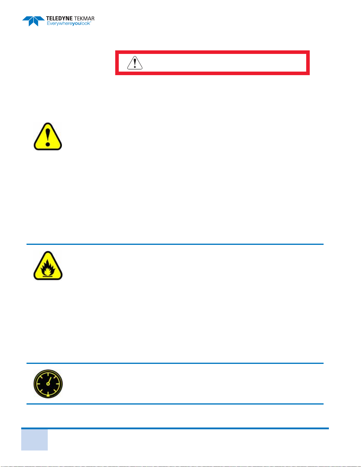
P.4 Notations and Hazard Severity Levels
This manual uses Notations and Hazard Severity Levels to emphasize information that
is important for instrument functionality and user and instrument safety. The four levels
consist of:
NOTE
Note is used for information and descriptions to ensure correct usage to
prevent damage of the instrument.
Caution
Cautions identify a potential hazard, which if not avoided, may result in minor
or moderate injury. This category can also warn you of unsafe practices, or
conditions that may cause property damage.
WARNING
Warnings identify a potentially hazardous condition, which if not avoided,
could result in death or serious injury.
DANGER
DANGER is limited to the most extreme situations to identify
an imminent hazard, which if not avoided, will result in death
or serious injury.
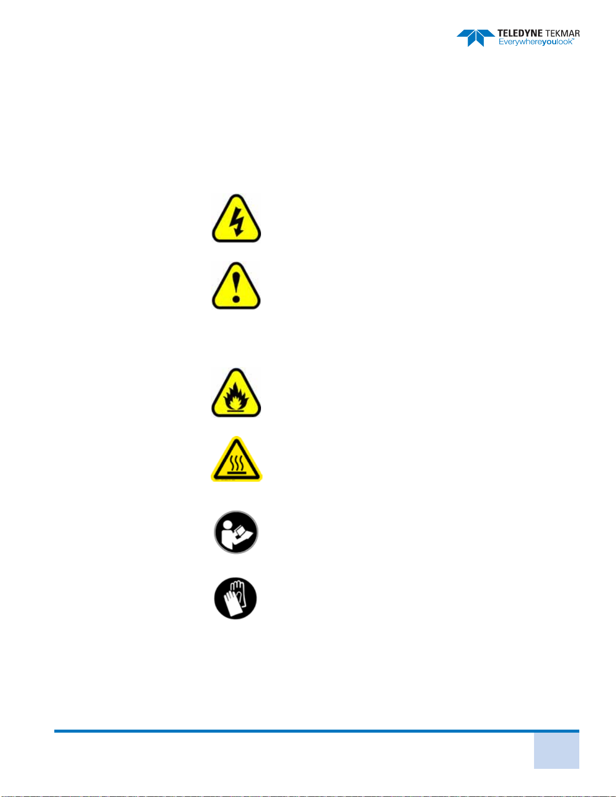
Lumin Safety Symbols
Lumin User Manual P - 3
P.5 Lumin Safety Symbols
The Lumin instrument is labeled in compliance with the marking and nomenclature
specified in the EN61010-1:2010 safety standard. The following symbols and their
associated signal words are used in the manual and on instrument labels.
L’instrument Lumin est étiqueté en conformité avec le marquage et la nomenclature
spécifiés dans le standard de sécurité EN61010-1:2010. Les étiquettes ci-dessous et leurs
marquages associés sont utilisés dans le manuel et sur l’étiquetage de l’instrument.
Electrical Hazard!
Risque électrique!
Warning/Caution! A hazardous or potentially hazardous situa-
tion that, if not avoided, will result in product and/or property
damage and possible injury and/or death.
Danger/Attention! Un risque ou une situation potentielle à ris-
que, qui n’est pas respectée, résultera dans le dommage du
produit et/ou des biens et la possibilité de blessures et/ou de
mort
Fire Hazard!
Risque de feu!
Burn hazard. Hot surface inside. Allow this area to cool before
servicing.
Risque de brulure. Surface chaude à l’intérieur. Attendre le
refroidissement de cette zone avant entretien
Read the Appropriate Documentation!
Lire la documentation appropriée
Skin Contact Hazard! Use protective gloves and other
appropriate PPE.
Risque au contact de la peau. Utiliser des gants de protection ou
autres équipements de protection personnel appropries.

Lumin Safety Labels
Lumin User Manual P - 5
P.6 Lumin Safety Labels
Electrical Ground
Prise de terre
WARNING: Electrical shock hazard. Do not operate without cover.
DANGER - Risque d’électrocution. Ne pas utiliser sans capot.
WARNING: To avoid electrical shock, disconnect supply before
changing fuses.
DANGER - Pour éviter le risque d’électrocution, débrancher l’alimen-
tation avant de remplacer les fusibles.
WARNING: For continued fire protection, replace with same type and
rating of fuses.
DANGER - Pour prévenir le risque d’incendie, remplacer avec des fus-
ibles de même type et de même caractéristique.
WARNING: Remove the power cable before performing maintenance
and/or servicing the instrument.
DANGER - Débrancher le câble d’alimentation avant toutes interven-
tions de maintenance et/ou d’entretien sur l’instrument.
CAUTION: Maximum pressure for carrier gas is 200 PSI (13.8 bar)
ATTENTION: La pression maximale pour le gaz porteur est de 200 PSI
(13.8 bar).
CAUTION: Inlet pressure recommended for sample gas is a minimum
of 65 PSI to maximum of 100 PSI (4.5 to 6.9 bar).
ATTENTION: La pression d’entrée recommandée pour le gaz échantil-
lonné doit être comprise entre 65 PSI et 100PSI (4.5 to 6.9 bar).
Power entry module requires:
La puissance de module d’entrée nécessite:
2 IEC 5 x 20 mm fuses
100V operation
T 10.0A – 250v
115V operation
T 10.0A – 250v
230V operation
T 5.0A – 250v
Working Safely
Lumin User Manual
P - 6
P.7 Working Safely
DANGER
If the equipment is used in a manner not specified herein, the
protection provided by the equipment may be impaired!
The Lumin weighs 27 lbs (12.2 kg). If this weight exceeds your lifting ability, lift and position the
Lumin with two people. Lift and position the Lumin by the base only.
Route tubing drain lines to slope downward only. Do not extend tubing into the waste bottle
more than 3 to 5” (7.6 to 12.7 cm). Failure to follow these directions may result in improper
drainage of the Lumin.
Please be aware that if the Lumin, its components, and/or accessories are used in a manner not
specified by Teledyne Tekmar, protection by the equipment may be impaired.
Only use replacement parts supplied or approved by Teledyne Tekmar when performing
maintenance on the Lumin. Use of unapproved parts could result in damage to the instrument,
as well as personal injury.
Running an improper method may damage the Lumin. Setting up a new method should be
performed by personnel who are properly trained, knowledgeable, and well acquainted with
the Lumin.
Ensure that the installation location allows the concentrator to be easily turned off and the
power cord disconnected, in the event of an emergency.
The circuit used to power the Lumin should be protected by a Certified/Listed 15/20 Circuit
Breaker for short circuit protection.
Do not plug the Lumin into an extension cord. An extension cord may overheat and cause a fire.
Do not replace the Lumin mains supply AC power cable with a cable of any other type or rating.
Ensure the power cable is routed away from, and is not capable of contacting, any hot surface.
Only replace fuses with those of the same type and rating. Refer to Section 5.22 "Power Entry
Module (PEM) Fuse Replacement".
To avoid the risk of fire and maintain optimum instrument performance, install the
concentrator on a non-flammable surface and maintain a minimum 6” (15.24 cm) perimeter
around the unit that is unobstructed by flammable material or other equipment.
NEVER use hydrogen or other flammable gas with the Lumin. Venting of this gas creates an
explosion hazard. Follow the manufacturer’s directions for safe handling of gas and chemicals.
Also refer to the Safety Data Sheets (SDSs) for information on specific chemicals.
To avoid injury to yourself or damage to the Lumin, do not exceed the recommended pressure
settings. Observe safety regulations when handling pressurized gas. For more information see
Matheson™ Gases Data Book (available from the Matheson Company, East Rutherford, New
Jersey)

Lumin User Manual P - 7
Sample and associated waste may contain hazardous and toxic substances. Follow the proper
safety and health practices, as well as anticipating all regulatory limitations before using or
disposing of chemicals.
To avoid electrical shock:
Do not operate without the panels, covers and guards installed.
Plug the power cord into a properly grounded outlet.
The Lumin uses extremely high voltage! To avoid electrical shock, turn OFF and
unplug before servicing.
To maintain fire protection, always replace fuses with the same type and rating of fuse.
Risk of Eye Injury. Wear safety glasses and other appropriate PPE. It is recommended that safety
glasses be worn at all times in the presence of pressurized gases.
This instrument contains heated components. Touching any heated zone during the operation
of the instrument can cause a burn. To prevent injury, allow areas with this label to cool before
servicing.
When accessing the sample mount, 4-way tee, moisture control system (MCS), analytical trap
compartment or 6-port valve (in the valve oven area), allow the components to cool to room
temperature.
Analytical Trap Sample Mount
4-Way Tee
6-Port Valve
MCS


1 - 1
Lumin User Manual
Chapter 1: Introduction
The Lumin is a modern laboratory instrument designed to concentrate Volatile Organic
Compounds (VOCs) from samples using the Purge and Trap (P&T) technique. The
Lumin uses advanced P&T technology that allows accelerated automatic processing of
liquid samples for analysis by Gas Chromatograph (GC). The Lumin purges VOCs from
liquids onto an analytical trap. The trap is then rapidly heated and the analytes are swept
with carrier gas onto the column for separation and detection.
1.1 Purge and Trap Background
1.1.1 Purge and Trap Fundamentals
When using a concentrator system, it is not essential to understand how it works.
However, a good grasp of the fundamentals helps you prevent problems and assists you
when you are faced with tasks such as method development and troubleshooting. This
section is not intended to be a full theoretical evaluation of P&T gas chromatography.
The primary purpose of this section is to help develop an understanding of how and why
compounds are concentrated. While gas chromatography is a very powerful analytical
tool, it does have several limitations. Many different techniques have gradually been
developed to overcome these limitations. These techniques are for a wide variety of
sample types. The limitations which P&T concentration is designed to overcome,
include:
1. Lack of sensitivity
GC detectors provide remarkable sensitivity. However, there are a number of areas
where greater sensitivity is necessary. These include:
Environmental Analysis - Many pollutants must be measured at low levels;
sometimes, in the sub-part per billion (ppb) range.
Flavor and Fragrance Analysis - The human nose is one of the most
sensitive detectors in existence. To provide an analytical system with
comparable sensitivity, some method of concentration is required.
2. Inability to tolerate water injections
Many GC columns and detectors do not perform well in the presence of water.
Water may drastically reduce the lifetime of the column and adversely affect the
detector performance.
3. The sample must be in vapor or vaporizable form
Gas chromatography operates as an interaction between vapor and liquid phases.
The sample must start out as a vapor. For this reason, there are many samples,
such as pollutants in soil or flavors in solid food, which cannot be directly
introduced into a GC.
The ability to analyze VOCs is a vital part of environmental monitoring, outgassing
studies, flavor or fragrance analysis, among others. P&T is a technique that
separates the VOCs from a matrix. After separation, the VOCs are then
concentrated and injected into the GC for separation and detection.

Chapter 1: Introduction
Lumin User Manual
1 - 2
1.1.2 Brief History
In the 1960’s, P&T was used in the study of bodily fluids. In the mid-to-late 1970’s, P&T
became a technique that was well-known and widely applied due the need to monitor
VOCs in drinking water. Using this technique, it was possible to detect sub-ppm level
VOCs of a wide variety. Today, P&T is routinely applied in the environmental area for the
analysis of VOCs in soil and water. The arrival of microprocessor-driven systems allows
the concentrator to be more precise and automated, giving the operator more time for
other projects.
1.2 Purge and Trap Operation Overview
A measured amount of sample is placed in a sealed vessel. The sample is purged with
inert gas, causing VOCs to be swept out of the sample. The VOCs are retained in an
analytical trap, which allows the purge gas to pass through to vent. The VOCs are then
desorbed by heating the trap, injected into the GC by back-flushing the trap with carrier
gas, and separated and detected by normal GC operation.
While purging and sweeping the sample with an inert gas sounds simple, it is in reality a
very complex process. Purging a sample to extract analytes is a gas extraction. There are
many factors that affect the efficiency of this extraction. The amount of each compound
purged is proportional to both its vapor pressure and its solubility in the sample. Both of
these are, in turn, affected by the sample temperature. Consider the case of a sample
sealed in a closed vial. Above the sample is a vapor space, which is usually referred to as
the headspace. If you allow the sample sufficient time, VOCs in the sample will migrate
into the vapor space. After a certain period of time at a constant temperature, the
concentration of the volatile compounds in each phase will be stabilized, the chemical
system will have reached equilibrium (Figure 1-1).
Figure 1-1 Headspace EquilibriumDiagram
Table of contents
Other Teledyne Tekmar Laboratory Equipment manuals


Popular Laboratory Equipment manuals by other brands


THORLABS
THORLABS M617F2 manual

Genetix
Genetix QPix Robot Manual

Science First
Science First Therm Bath III manual

Agilent Technologies
Agilent Technologies 53150A Service guide

Steinberg Systems
Steinberg Systems SBS-LZ-300D user manual

Lifecanvas Technologies
Lifecanvas Technologies SMARTLABEL Quick installation guide


