Teledyne 5800 Use and care manual

1
11
CAUTION
CAUTION
5800 115V Refrigeration Module
Removal and Replacement
Instruction Sheet 60-4702-048
Revision H, November 8,
2019
These instructions cover the 4700 and 5800 115V
refrigerator module replacement. Before attempting to
remove and replace a module observe the following
precautions:
Removing a module exposes you to electrical and
mechanical hazards. Always disconnect the AC
powercord before attemptingto removeany
module. Only trained service personnel may
remove or replace these modules.
Modules contain circuit boards and sensitive electronics
that can be damaged by a discharge of static electricity.
Avoid touching the internal components. Only handle
the module by the edges or exterior surfaces.
Electricalconnectorsandwires canbe damagedif
improperly handled. Electrical connectors must only be
handled by the connector body. Never grasp the wires
or use tools to disconnect a connector. Never allow a
module to hang by its wiring.
Removing the Module - Serial Number
216B and Newer
Complete the following to remove the existing
refrigerator module.
1. Unplug the line cord to remove the AC power.
2. Remove the coil shield, back cover, and
insulation panel (Figure 1). When removing the
foam insulation panel, take precautions not to
damage the foam around the tubing (see inset,
Figure 1).
Refrigeration module
Foam insulation panel
Back cover
Coil Shield
Earth groundbondingconductor.Do not
removeor disconnect.Ifthis conductormust
bedisconnected to remove a module, it must
be reconnected when installing the
replacement module.
Required Parts andTools
●Replacement refrigeration module assembly:
❍
115 VAC sampler (P/N 60-5804-190)
❍
Nylon cable tie (P/N 489-0110-00)
❍
Permagum sealant (P/N 090-0200-38)
●#3 Phillips screwdriver
●/32" nut driver or socket wrench
●Wire cutters
●Flat-blade screwdriver
●Putty knife
Foam insulation panel
Figure 1: Open rear compartment
3. Cut the cable tie holding the power cord that
runs through the refrigeration assembly
(Figure 2).
Cut cable tie
1. PermagumisaregisteredtrademarkofthePresstiteEngineering
Company.
Figure 2: Cut cable tie to free line cord
CAUTION
WARNING

Instruction Sheet 60-4702-048 Revision H, November 8, 2019
Gray
Blue
Brown
Black
Heater
Wire
Green/
yellow
4. Remove the refrigeration module mounting
screws (Figure 3).
5. Carefully pull the module out and rotate
clockwise to expose the wiring connectors. The
bushing holding the AC line cord in place should
slide along the cord (see inset, Figure 3). During
reinstallation, the slack created in this step must
be removed.
Keep the module as close to the refrigerator body as
possibleto avoid pulling the wiring taut and damaging
the connectors.
Figure 3: Remove refrigeration module mounting
screws
6. Remove the terminal cover of the compressor
(Figure 4). For serial number 219K02629 or
newer, remove the screw and lock washer that
hold the green/yellow ground wire in place on
the compressor.
Figure 4: Access compressor overload
Ascrewdriver
may be used to release the latch.
7. Disconnect the four (4) compressor wires from
the power supply cable (Figure 5).
a. While holding the overload relay in place,
disconnect the brown wire.
b. Disconnect the blue wire from the capacitor
and relay assembly from the gray wire on the
power supply cable.
c. Disconnect the black heater wire from the
black wire on the power supply cable.
d. With the 11/32" nut driver or socket wrench,
remove the nut holding the green/yellow
ground wire on the module chassis.
Figure 5: Disconnect compressor wires
8. The evaporator temperature sensor is mounted
on the sixth coil up on the evaporator (Figure 6)
and has a black rubber molded housing. Cut the
ties holding this sensor in place and move it out
of the frame.
Figure 6: Remove evaporator temperature sensor
Pull module out and
rotate clockwise
Line cord bushing
CAUTION

Instruction Sheet 60-4702-048 Revision H, November 8, 2019
Bushing
Power supply
cables
9. Remove the power cord from the refrigeration
assembly.
a. Slide the bushing sideways away from the
refrigeration module until it is free (Figure 7).
Avoid bending the refrigeration tubing.
b. Pull the power cord through the module.
Figure 7: Remove line cord from module
Module Replacement
Complete the following to install the new refrigerator
module.
10. Ensure that the control wiring runs through the
channel in the refrigerator body (Figure 8).
Two thick, black cables connect the power supply with
the AC and compressor (Figure 8). Ensure that
cables are side by side and not crossed during
reassembly.
Figure 8: Rear view with module removed
11. Install the evaporator temperature sensor at the
top of the sixth coil (Figure 6), using the cable
ties provided.
To operate correctly, the sensor must be
mounted in the exact position illustrated in
Figure 6.
When installing the black
molded sensor do not
overtighten the cable tie on the
sensor body, as internal
damage may occur. The sensor
should be snug against the coil,
but the rubber housing should
not be visibly dented.
12. Reconnect the four (4) compressor wires to the
power supply cable (Figure 5):
a. Connect the brown wire to the overload relay.
b. Connect the gray wire from the power supply
to the blue wire from the capacitor and relay
assembly.
c. Connect the black wire from the power
supply to a black wire from the heater.
d. With the 11/32" wrench, connect the green/
yellow ground wire with the nut to the
threaded standoff on the frame.
13. Reinstall the terminal cover onto the
compressor.
14. Connect the green/yellow ground wire from the
module chassis to the compressor with the
included screw and lock washer.
Earth ground bonding conductor. Ensure that
the green/yellow wire is reconnected to this
terminal.
15. Slide the refrigeration module to the rear of the
refrigerator and place the drain tube in the drip
pan on the module (Figure 9).
Figure 9: Position drain tube in fronthalfofthe drip
pan
16. Ensure the black gasket is aligned and gasket
nubs are inserted in corresponding holes onthe
frame of the refrigerator module (Figure 10).
CAUTION
Note
Note

Instruction Sheet 60-4702-048 Revision H, November 8, 2019
Figure 10: Position gasket on refrigeration module
frame and ensure each gasket nub is inserted in
corresponding hole
17. Route the AC power cord through the
refrigeration module and secure it in place with
the bushing (Figure 11).
Bushing
Figure 11:SecureAC PowerCord (Fulllengthofline
cord not depicted)
18. Install the module, tipping the top back while
sliding the bottom forward. When the bottom of
the system is in place, push the top into place
(Figure 12). Ensure the slack in the power cord is
removed before securing refrigeration module
frame.
Push top
in
second.
Push
bottom in
first.
Figure 12: Slide module into place
When reinstalling the refrigeration module, do not pinch
the sensor wiring.
When reinstalling all self-tapping screws, avoid
destroying the plastic threads. First seat each screw in
its hole and, without pressing down, rotate the screw
counter-clockwise until it falls into its thread groove with
a “click.”Then tighten the screw.
19. Reinstall the refrigeration module mounting
screws (Step 4).
20. Install the cable tie to secure the power cord
that runs through the refrigeration assembly
(Figure 13).
Duringreinstallation,Ensuretheslackinthepowercord
is removed before securing refrigeration module frame.
Install
cable tie
Figure 13: Install cable tie to secure power cord
CAUTION
CAUTION
Gasket
Nub
CAUTION

Instruction Sheet 60-4702-048 Revision H, November 8, 2019
PROGRAM
CONFIGURE
VIEW LOG
SELECT DIAG: (<-->)
TEST 'RAM'
Refrigeration module
Insulation panel
Back cover
Cover brace
21. Reinstall the coil shield, back cover, and
insulation panel (Figure 1). When installing the
foam insulation panel, take precautions not to
damage the foam around the tubing (see inset,
Figure 1).
22. Restore AC power to the 5800 refrigerator.
23. Review the refrigerator temperature diagnostic
test, as described in the following section.
RefrigeratorTemperature Diagnostic
The REFRIG TEMPERATURE diagnostic test displays the
temperature of the refrigerated compartment.
To start the diagnostics from the standby screen:
1. Select the CONFIGURE option and press Enter.
2. Press the left arrow button until the RUN
DIAGNOSTICS option is displayed. Press Enter.
3. Press the right arrow key 7 times to display
REFRIG TEMPERATURE. Press Enter to start the test.
When this test is started, the sampler will display the
temperature until the Stop or Enter button is pressed.
There is no pass or fail. This test provides continuous
temperature monitoring.
As the refrigerator cycles off and on, the reported
temperature will rise above and below the set
temperature. However, the average reported
temperature should be the same as the configured
temperature. The evaporator temperature may read as
low as –20 °C at times; this is considered normal.
If the screen displays an asterisk (*) or inaccurate
temperature reading, the temperature sensor cable may
be malfunctioning.
Removing the Module - Serial Number
216B and Older
Complete the following to remove the existing
refrigerator module.
1. Unplug the line cord to remove the AC power.
2. Remove the cover brace, back cover, and
insulation panel (Figure 14).
Figure 14: Open rear compartment
3. Cut the cable tie holding the power cord that
runs through the refrigeration assembly
(Figure 15).
Figure 15: Cut cable tie to free line cord
4. Remove the refrigeration module mounting
screws (Figure 16).
Note that the refrigeration module has an adhesive
strip just above the rear coils. The bottom center
screw may be slightly hidden by this.
5. Carefully pull the module out and rotate
clockwise to expose the wiring connectors. The
bushing holding the AC line cord in place should
slide along the cord (see Figure 16, inset). During
reinstallation, the slack created in this step must
be removed.
Note
REFRIG TEMPERATURE:
AIR= C EVAP= C
SELECT DIAG: (<-->)
REFRIG TEMPERATURE
SELECT OPTION: (<--
>)
RUN DIAGNOSTICS

Instruction Sheet 60-4702-048 Revision H, November 8, 2019
Fan
Brown
Black
Capacitor
and relay
Blue
Keep the module as close to the refrigerator body as
possibleto avoid pulling the wiring taut and damaging
the connectors.
7. Disconnect the three (3) compressor wires from
the power supply cable (Figure 18).
a. While holding the overload relay in place,
disconnect the brown wire.
Pull module out and
rotate clockwise
Adhesive strip
Line cord bushing
Figure 16: Remove refrigeration module
6. Remove the terminal cover of the compressor
(Figure 17).
Figure17:Access compressoroverload and relay
A screwdriver may be used to release the latch.
If the unit has a newer power supply with four wires
(brown, gray, black and green) refer to Step 7 in
section 216B on newer wiring instructions.
b. Disconnect the blue wire from the blue wire
on the power supply cable or the blue wire
from the capacitor and relay.
c. With the 11/32" nut driver or socket wrench,
remove the nut holding the green/yellow
ground wire on the module chassis.
Figure 18: Disconnect compressor wires
8. The evaporator temperature sensor is mounted
on the sixth coil up on the evaporator
(Figure 19). Note that some older 4700 models
have a metal sensor, while current models have a
black rubber molded housing. Cut the ties
holding the evaporator sensor in place and move
it out of the frame.
Older (4700 only) Current (4700 & 5800)
Figure 19: Remove evaporator temperature sensor
Note
CAUTION

Instruction Sheet 60-4702-048 Revision H, November 8, 2019
Bushing
9. Remove the power cord from the refrigeration
assembly.
a. Slide the bushing sideways away from the
refrigeration module until it is free. (Figure
20). Avoid bending the refrigeration tubing.
b. Pull the power cord through the refrigeration
module.
Figure 20: Remove line cord from module
Module Replacement
Complete the following to install the new refrigerator
module.
10. Ensure that the power supply cables are routed
through the proper channels in the refrigerator
housing (Figure 21).
Two thick, black cables connect the power supply with
the AC and compressor. Ensure that cables are side
by side and not crossed during reassembly.
11. Using a flat screwdriver or putty knife, remove
the adhesive strips from the refrigerator housing
(Figure 21).
Figure 21: Rear view with module removed
Route
power supply cables then remove adhesive strips
12. Seal the indicated areas with Permagum1 sealing
compound (Figure 22).
1. PermagumisaregisteredtrademarkofthePresstiteEngineering
Company.
Figure 22: Seal grooves on refrigerator housing
with Permagum
13. Route the AC power cord through the
refrigeration module and secure it in place with
the bushing (Figure 23).
Bushing
Figure 23:SecureAC PowerCord (Fulllengthofline
cord not depicted)
14. Install the evaporator temperature sensor at the
top of the sixth coil (Figure 19), using the cable
ties provided.
To operate correctly the sensor must be
mounted in the exact position illustrated in
Figure 19.
When installing the black
molded sensor, do not
overtighten the cable tie on the
sensor body, as internal
damage may occur. The sensor
should be snug against the coil,
but the rubber housing should
not be visibly dented.
15. Connect the compressor power wires (refer to
Figure 18):
If unit has newer power supply with four wires (brown,
gray, black and green) refer to step 12 above in the
216B and newer wiring instructions.
a. Connect the brown wire to the overload.
b. Connect the blue wire to the blue wire from
the new capacitor and relay.
Note
Note
Power supply
cables
Adhesive strips
Note
Permagum

Instruction Sheet 60-4702-048 Revision H, November 8, 2019
Gasket
Nub
CAUTION
CAUTION
c. With the 11/32" wrench, connect the green and
yellow ground wire with the nut to the
threaded standoff on the frame.
The black wire from the heater is not utilized.
16. Reinstall the terminal cover that was removed in
step 6.
17. Connect the green/yellow ground wire from the
module chassis to the compressor with the
included screw and lock washer.
Earth ground bonding conductor. Ensure the
green/yellow wire is reconnected to this
terminal.
18. Slide the refrigeration module to the rear of the
refrigerator and place the drain tube in the drip
pan on the module (Figure 24).
Figure 24: Position drain tube in fronthalfof drip pan.
19. Ensure the black gasket is aligned and gasket
nubs are inserted in corresponding holes onthe
frame of the refrigerator module (Figure 25).
Figure 25: Position gasket on refrigeration module
frame and ensure each gasket nub is inserted in
corresponding hole
20. Route the AC power cord through the
refrigeration module and secure it in place with
the bushing (Figure 26).
Bushing
Figure 26:SecureAC Power Cord(Fulllengthofline
cord not depicted)
When reinstalling the refrigeration module, do not pinch
the sensor wiring.
21. Install the module, tipping the top back while
sliding the bottom forward. When the bottom of
the system is in place, push the top into place
(Figure 27). Ensure the slack in the power cord is
removed before securing refrigeration module
frame.
Push top
in
second.
Push
bottom in
first.
Figure 27: Slide module into place
When reinstalling all self-tapping screws, avoid
destroying the plastic threads. First seat each screw in
its hole and, without pressing down, rotate the screw
counter-clockwise until it falls into its thread groove with
a “click.”Then tighten the screw.
22. Reinstall the refrigeration module mounting
screws (Step 4).
CAUTION
Note

Instruction Sheet 60-4702-048 Revision H, November 8, 2019
PROGRAM
CONFIGURE
VIEW LOG
SELECT DIAG: (<-->)
TEST 'RAM'
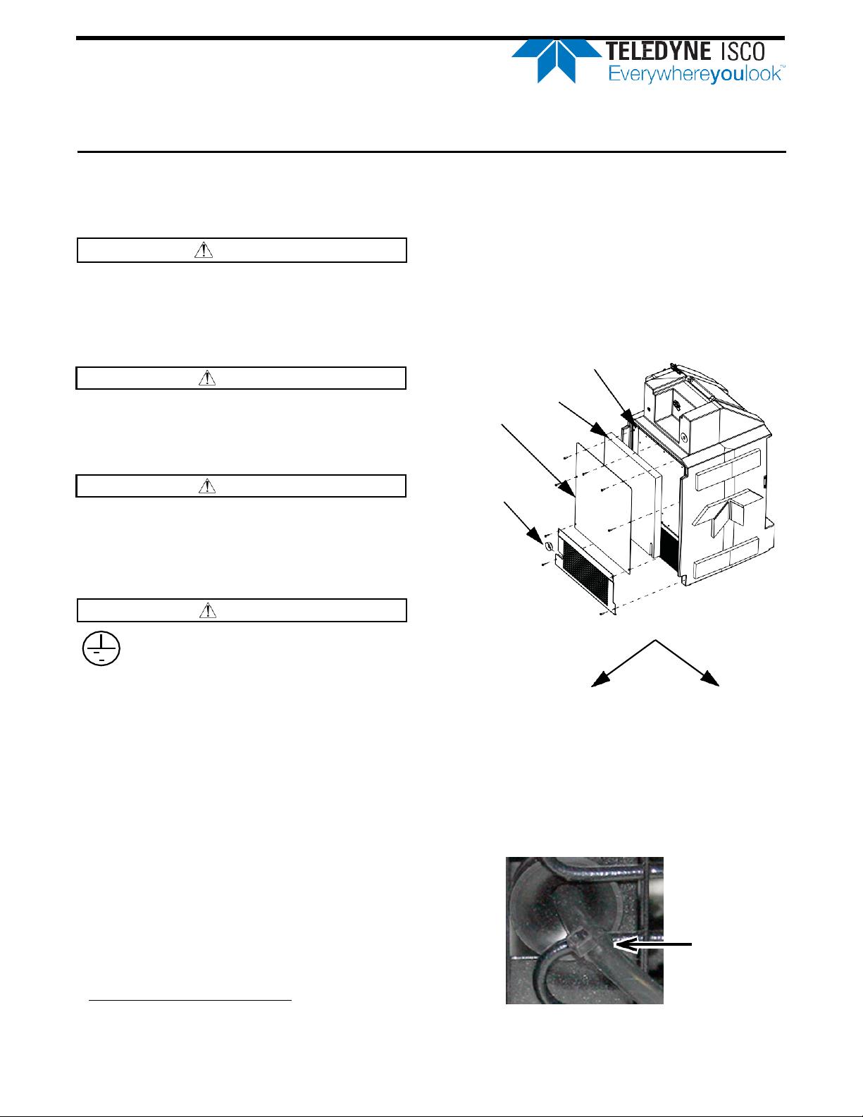
23. Install the cable tie to secure the power cord
that runs through the refrigeration assembly
(Figure 28). Ensure the slack in the power cord is
removed before securing refrigeration module
frame.
Install
cable tie
Figure 28: Install cable tie tosecure power cord
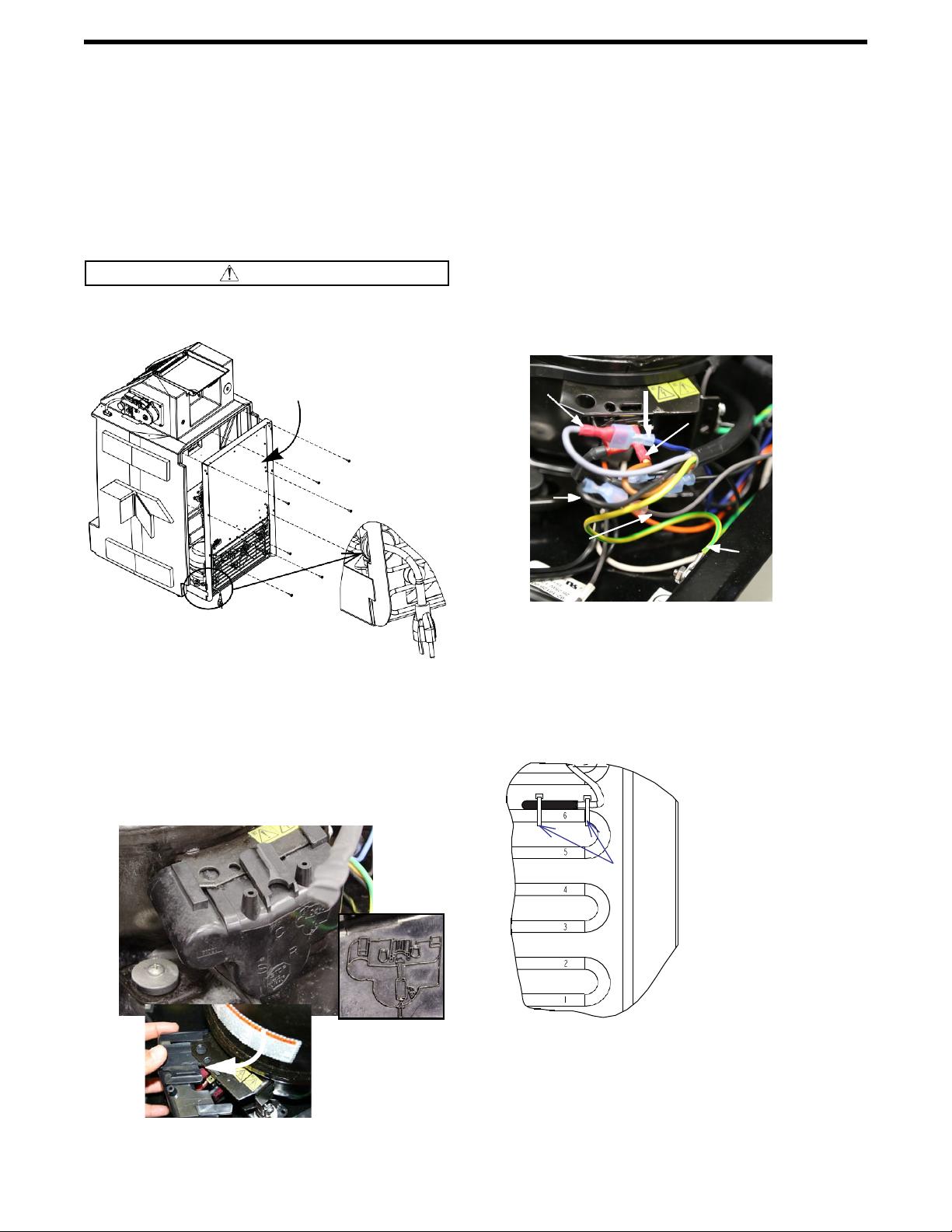
a. Mark two corners of the foam insulation with
1 1/2” x 4 1/2” lines (Figure 29).
Figure 29: Mark foam insulation
b. Cut the insulation panel as marked in the
previous step (Figure 30).
Figure 30: Cut foam insulation
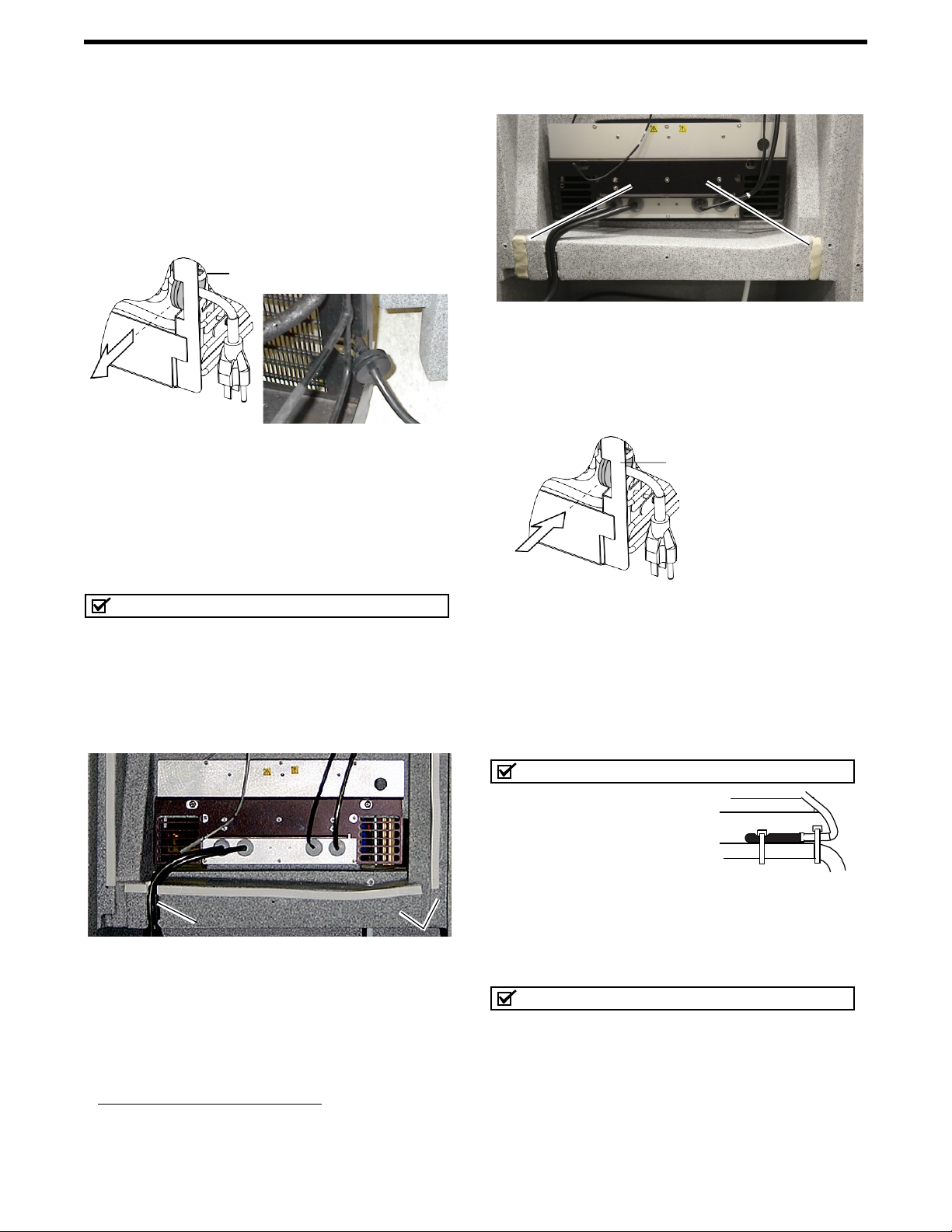
c. Install foam panel on the refrigeration
module, taking precautions not to damage the
foam around the tubing (Figure 31).
Figure 31: Install the insulation panel
24. Reinstall the cover brace, back cover, and
insulation panel (Figure 14).
a. Restore AC power to the 5800 refrigerator.
25. Review the refrigerator temperature diagnostic
test, as described in the following section.
RefrigeratorTemperature Diagnostic
The REFRIG TEMPERATURE diagnostic displays the
temperature of the refrigerated compartment.
To start the diagnostics from the standby screen:
1. Select the CONFIGURE option and press Enter.
2. Press the left arrow button until the RUN
DIAGNOSTICS option is displayed. Press Enter.
3. Press the right arrow key 7 times to display
REFRIG TEMPERATURE. Press Enter to start the test.
When this test is started, the sampler should display
the temperature until you press the Stop or Enter
button. There is no pass or fail. This test simply
provides continuous temperature monitoring.
As the refrigerator cycles off and on, the reported
temperature will rise above and below the set
temperature. However, the average reported
temperature should be the same as the configured
temperature. The evaporator temperature may at times
read as low as –20° C; this is considered normal.
If the screen displays an asterisk (*) or inaccurate
temperature reading, the temperature sensor cable may
be malfunctioning.
Last modified November 8, 2019
Teledyne Isco
P.O. Box 82531, Lincoln, Nebraska, 68501 USA
Toll-free: (866) 298-6174 • Phone: (402) 464-0231 • Fax: (402) 465-3001
E-mail: IscoService@teledyne.com
Teledyne Isco is continually improving its products and reserves the right to change product
specifications, replacement parts, schematics, and instructions without notice.
REFRIG TEMPERATURE:
AIR= C EVAP= C
SELECT DIAG: (<-->)
REFRIG TEMPERATURE
SELECT OPTION: (<--
>)
RUN DIAGNOSTICS
1 1/2 x 4 1/2 marks
Other manuals for 5800
4
Table of contents
Other Teledyne Control Unit manuals