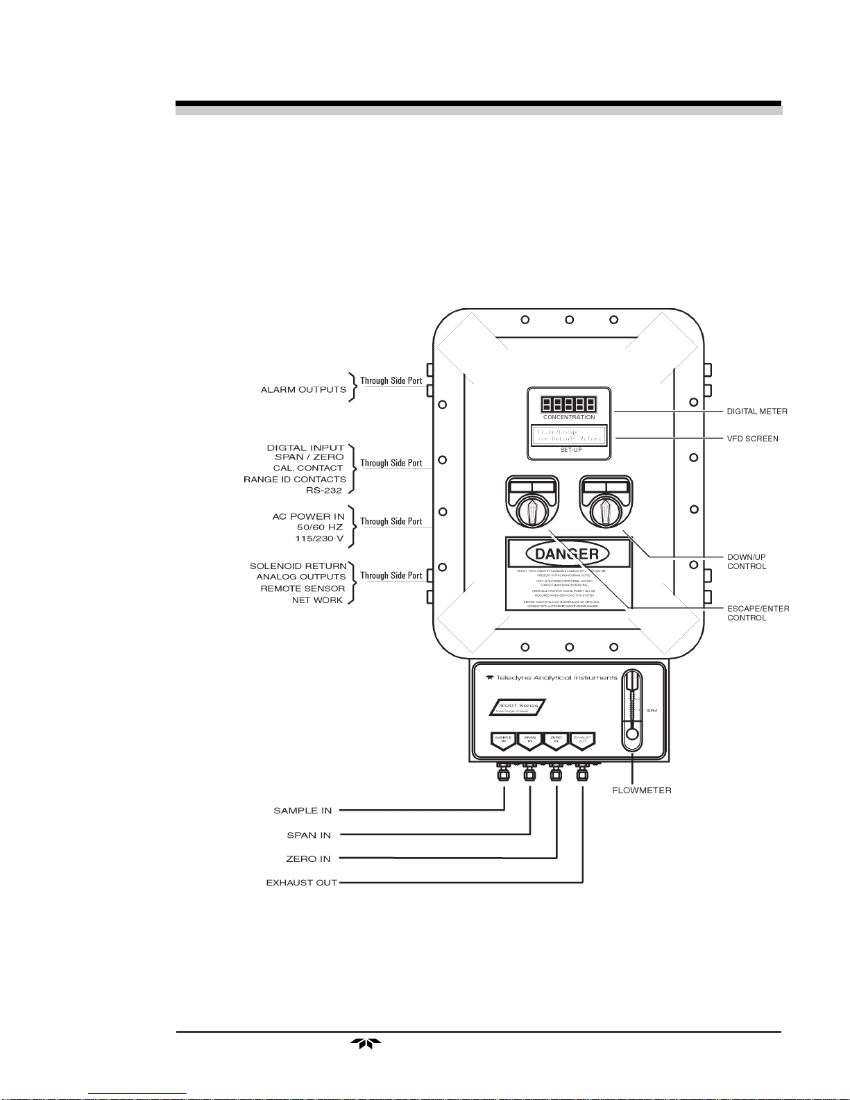
Teledyne 3020T User manual

i
Trace Oxygen Analyzer
Teledyne Analytical Instruments
OPERATING INSTRUCTIONS FOR
Model 3020T
Trace Oxygen Analyzer
HIGHLY TOXIC AND OR FLAMMABLE LIQUIDS OR GASES MAY BE PRESENT IN THIS
MONITORING SYSTEM.
PERSONAL PROTECTIVE EQUIPMENT MAY BE REQUIRED WHEN SERVICING THIS SYSTEM.
HAZARDOUS VOLTAGES EXIST ON CERTAIN COMPONENTS INTERNALLY WHICH MAY PER-
SIST FOR A TIME EVEN AFTER THE POWER IS TURNED OFF AND DISCONNECTED.
ONLY AUTHORIZED PERSONNEL SHOULD CONDUCT MAINTENANCE AND/OR SERVICING.
BEFORE CONDUCTING ANY MAINTENANCE OR SERVICING CONSULT WITH AUTHORIZED
SUPERVISOR/MANAGER.
DANGER
P/N M65908
11/22/99
ECO # 99-0459

ii
Model 3020T
Teledyne Analytical Instruments
Copyright©1999TeledyneAnalyticalInstruments
All Rights Reserved. No part of this manual may be reproduced, transmitted, tran-
scribed, stored in a retrieval system, or translated into any other language or computer
language in whole or in part, in any form or by any means, whether it be electronic,
mechanical, magnetic, optical, manual, or otherwise, without the prior written consent of
TeledyneAnalyticalInstruments,16830ChestnutStreet,CityofIndustry,CA 91749-1580.
Warranty
This equipment is sold subject to the mutual agreement that it is warranted by us free
from defects of material and of construction, and that our liability shall be limited to
replacing or repairing at our factory (without charge, except for transportation), or at
customer plant at our option, any material or construction in which defects become
apparent within one year from the date of shipment, except in cases where quotations or
acknowledgements provide for a shorter period. Components manufactured by others bear
the warranty of their manufacturer. This warranty does not cover defects caused by wear,
accident, misuse, neglect or repairs other than those performed by Teledyne or an autho-
rized service center. We assume no liability for direct or indirect damages of any kind and
the purchaser by the acceptance of the equipment will assume all liability for any damage
which may result from its use or misuse.
We reserve the right to employ any suitable material in the manufacture of our
apparatus, and to make any alterations in the dimensions, shape or weight of any parts, in
so far as such alterations do not adversely affect our warranty.
ImportantNotice
This instrument provides measurement readings to its user, and serves as a tool by
which valuable data can be gathered. The information provided by the instrument may
assist the user in eliminating potential hazards caused by his process; however, it is
essential that all personnel involved in the use of the instrument or its interface, with the
process being measured, be properly trained in the process itself, as well as all instrumenta-
tion related to it.
The safety of personnel is ultimately the responsibility of those who control process
conditions. While this instrument may be able to provide early warning of imminent danger,
it has no control over process conditions, and it can be misused. In particular, any alarm or
control systems installed must be tested and understood, both as to how they operate and
as to how they can be defeated. Any safeguards required such as locks, labels, or redun-
dancy, must be provided by the user or specifically requested of Teledyne at the time the
order is placed.
Therefore, the purchaser must be aware of the hazardous process conditions. The
purchaser is responsible for the training of personnel, for providing hazard warning
methods and instrumentation per the appropriate standards, and for ensuring that hazard
warning devices and instrumentation are maintained and operated properly.
Teledyne Analytical Instruments, the manufacturer of this instrument, cannot
accept responsibility for conditions beyond its knowledge and control. No statement
expressed or implied by this document or any information disseminated by the manufactur-
er or its agents, is to be construed as a warranty of adequate safety control under the
user’s process conditions.

iii
Trace Oxygen Analyzer
Teledyne Analytical Instruments
SpecificModelInformation
Theinstrumentforwhichthismanualwassuppliedmayincorporateoneor
moreoptionsnotsuppliedinthestandardinstrument.Commonlyavailable
optionsarelistedbelow,withcheckboxes.Anythatareincorporatedinthe
instrumentforwhichthismanualwassuppliedareindicatedbyacheckmarkin
thebox.
InstrumentSerialNumber:__________________________
Theinstrumentwiththeaboveserialnumberhasthefollowing
Options:
❏3020T-C Threegasinputs,forsample,zeroandspangases,with
threesolenoid-actuatedgas-flowcontrolvalvesbuiltin.
Valvesareautomaticallysynchronizedtotheanalyzer's
electroniccontrolsequences.
❏3020T–F Built-in flame arresters for Groups C and D service.
❏3020T–G Built-in flame arresters for Groups C and D service, plus
gas-control valves as in –C option, above.
❏3020T–H Built-inflamearrestersforGroupB(hydrogen)service.
❏3020T–I Built-inflamearrestersforGroupB(hydrogen)service,
plus gas-control valves as in –C option, above.
❏19" Rack Mount
The 19" Relay Rack Mount units are available with
either one or two series 3000 analyzer Control Units
installed in a standard 19" panel and ready to mount in a
standard rack. See Appendix for details.
❏CellClass* ____________________(L-2C standard).
EnterClass Designation
* See Part II, Chapter 2 and/or any addendum that may be
attachedtothismanualforcellspecifications.

iv
Model 3020T
Teledyne Analytical Instruments
Table of Contents
1 Introduction
1.1 Overview........................................................................ 1-1
1.2 Typical Applications....................................................... 1-1
1.3 Main Features of the Analyzer ....................................... 1-1
1.4 Model Designations ....................................................... 1-2
1.5 OperatorInterface .......................................................... 1-3
1.5.1 UP/DOWN Switch.................................................. 1-4
1.5.2 ESCAPE/ENTER Switch....................................... 1-4
1.5.3 Displays................................................................. 1-5
1.6 Recognizing Difference Between LCD & VFD............... 1-5
1.7 Rear Panel Equipment Interface .................................... 1-5
1.7.1 Electrical Connector Panel .................................... 1-5
1.7.2 Gas Connector Panel............................................. 1-7
2 OperationalTheory
2.1 Introduction .................................................................... 2-1
2.2 Micro-Fuel Cell Sensor .................................................. 2-1
2.2.1 Principles of Operation ............................................ 2-1
2.2.2 Anatomy of a Micro-Fuel Cell .................................. 2-2
2.2.3 Electrochemical Reactions ...................................... 2-3
2.2.4 The Effect of Pressure.............................................. 2-4
2.2.5 Calibration Characteristics ...................................... 2-4
2.3 Sample System.............................................................. 2-5
2.4 Electronics and Signal Processing ................................ 2-6
2.5 Temperature Control ...................................................... 2-8
3 Installation
3.1 Unpacking the Analyzer................................................. 3-1
3.2 Mounting the Analyzer ................................................... 3-1
3.3 Electrical Connections ................................................... 3-3
3.3.1 Primary Input Power............................................... 3-4
3.3.2 Fuse Installation..................................................... 3-4
3.3.3 Analog Outputs ...................................................... 3-4
3.3.4 Alarm Relays ......................................................... 3-6
3.3.5 Digital Remote Cal Inputs...................................... 3-7
3.3.6 Range ID Relays ................................................... 3-9
3.3.7 NetworkI/O ............................................................ 3-9
3.3.8 RS-232 Port ........................................................... 3-9
3.3.9 Remote Sensor and Solenoid Valves ....................3-10
3.4 Installing the Micro-Fuel Cell ........................................ 3-11

v
Trace Oxygen Analyzer
Teledyne Analytical Instruments
3.5 Gas Connections .......................................................... 3-12
3.6 Testing the System........................................................ 3-14
4 Operation
4.1 Introduction .................................................................... 4-1
4.2 Using the Controls ......................................................... 4-1
4.2.1 Mode/Function Selection ....................................... 4-2
4.2.1.1 Analysis Mode ............................................... 4-2
4.2.1.2 Setup Mode ................................................... 4-2
4.2.2 Data Entry.............................................................. 4-4
4.2.2.1 ENTER .......................................................... 4-4
4.2.2.2 ESCAPE........................................................ 4-4
4.3 The AUTO-CAL Function............................................... 4-5
4.4 The PWD Function ........................................................ 4-5
4.4.1 Entering the Password........................................... 4-6
4.4.2 Installing or Changing the Password ..................... 4-7
4.5 The LOGOUT Function.................................................. 4-8
4.6 The VERSION Screen ................................................... 4-8
4.7 The SELF TEST Function.............................................. 4-9
4.8 The ZERO and SPAN Functions ................................... 4-9
4.8.1 Zero Cal................................................................. 4-10
4.8.1.1 Auto Mode Zeroing ........................................ 4-10
4.8.1.2 Manual Mode Zeroing.................................... 4-11
4.8.1.3 Cell Failure .................................................... 4-11
4.8.2 Span Cal................................................................ 4-12
4.8.2.1 Auto Mode Spanning ..................................... 4-12
4.8.2.2 Manual Mode Spanning................................. 4-13
4.9 The ALARMS Function.................................................. 4-14
4.10 The RANGE Function.................................................... 4-16
4.10.1 Setting the Analog Output Ranges......................... 4-16
4.10.2 Fixed Range Analysis............................................ 4-17
4.11 The CONTRAST Function............................................. 4-18
4.12 The STANDBY Function................................................ 4-18
4.13 The
Analysis Mode ........................................................
4-19
Maintenance
5.1 Routine Maintenance..................................................... 5-1
5.2 Major Internal Components............................................ 5-1
5.3 Cell Replacement .......................................................... 5-2
5.3.1 Storing and Handling Replacement Cells ............... 5-3
5.3.2 When to Replace a Cell........................................... 5-3
5.3.3 Removing the Micro-Fuel Cell ................................. 5-4

vi
Model 3020T
Teledyne Analytical Instruments
5.3.4 Installing a New Micro-Fuel Cell.............................. 5-6
5.2.5 CellWarranty ........................................................... 5-6
5.4 Fuse Replacement......................................................... 5-7
5.5 System Self Diagnostic Test........................................... 5-7
Appendix
A-1 Specifications ................................................................ A-1
A-2 Recommended 2-Year Spare Parts List ......................... A-3
A-3 Drawing List................................................................... A-4
A-4 Application Notes on Restrictors, Pressures & Flow...... A-4
A-5 Material Safety Data Sheet ............................................ A-5

1-1
Trace Oxygen Analyzer Introduction 1
Teledyne Analytical Instruments
Introduction
1.1 Overview
The Teledyne Analytical Instruments Model 3020T Trace Oxygen
Analyzerisaversatilemicroprocessor-basedinstrumentfordetectingoxygen
atthe parts-per-million (ppm) level in avariety ofgases. Thismanualcovers
theModel 3020T, trace oxygen, explosion-proof,bulkhead-mountunits
only.
1.2 Typical Applications
A few typical applications of the Model 3020T are:
• Monitoringinertgasblanketing
• Airseparationandliquefaction
• Chemicalreactionmonitoring
• Semiconductormanufacturing
• Petrochemicalprocesscontrol
• Qualityassurance
• Gasanalysiscertification.
1.3 Main Features of the Analyzer
The Model 3020T Trace Oxygen Analyzer is sophisticated yet simple
to use. The main features of the analyzer include:
• A2-line alphanumeric displayscreen,drivenby microprocessor
electronics,thatcontinuouslypromptsandinformstheoperator.
• High resolution, accurate readings of oxygen content from low
ppm levels through 25%. Large, bright, meter readout.
• Stainlesssteelcellblock.

1-2
1 Introduction Model 3020T
Teledyne Analytical Instruments
• Advanced Micro-Fuel Cell, redesigned for trace analysis, has an
expected life of one year.
• Versatile analysis over a wide range of applications.
• Microprocessorbasedelectronics:8-bitCMOSmicroprocessor
with 32 kB RAM and 128 kB ROM.
• Three user definable output ranges (from 0-10 ppm through 0-
250,000 ppm) allow best match to users process and equipment.
• Air-calibrationrangefor convenient spanning at20.9 %.
• AutoRanging allows analyzer to automatically selectthe proper
presetrange for a givenmeasurement.Manual override allows
the user to lock onto a specific range of interest.
• Twoadjustableconcentrationalarmsandasystemfailurealarm.
• Extensiveself-diagnostictesting,atstartupandondemand, with
continuouspower-supplymonitoring.
• RS-232 serial digital port for use with a computer or other digital
communicationdevice.
• Four analog outputs: two for measurement (0–1 V dc and
Isolated 4–20 mA dc) and two for range identification.
1.4 Model Designations
3020T: Standardmodel.
3020T-C: In addition to all standard features, this model also has
separate ports for zero and span gases, and built-in control
valves. The internal valves are entirely under the control of
the3020Telectronics,toautomaticallyswitchbetween gases
insynchronizationwiththeanalyzer’soperations
3020T-F: Flame arrestors for Groups C and D installed.
3020T-G: Flame arrestors for Groups C and D, & -C option, installed.
3020T-H: Flamearrestors for Group B (hydrogen) installed.
3020T-I: Flame arrestors for Group B, & -C option, installed.
All of the above options are available in combination.

1-3
Trace Oxygen Analyzer Introduction 1
Teledyne Analytical Instruments
1.5 Operator Interface
All controls and displays on the standard 3020T are accessible from
outside the housing. The instrument has two simple operator controls. A
digitalmeter,analphanumericdisplay,andasample flowmeter give the
operator constant feedback from the instrument. See Figure 1-1. The controls
are described briefly here and in greater detail in chapter 4.
Figure 1-1: Model 3020T Controls, Indicators, and Connectors

1-4
1 Introduction Model 3020T
Teledyne Analytical Instruments
1.5.1 UP/DOWN Switch
Functions: The UP/DOWN switch is used to select the function to be
performed. Choose UP or DOWN to scroll through the following list of
elevenfunctions:
•Auto-Cal Setupanautomaticcalibrationsequence.
•PWD Installapasswordtoprotectyouranalyzersetup.
• Logout Locks Setup Mode.
• Version Displays model and version of analyzer.
•Self-Test Runsinternaldiagnosticprogram,displaysresults.
•Span Spancalibratetheanalyzer.
•Zero Zerocalibratetheanalyzer.
•Alarms Setthealarmsetpointsandattributes.
•Range Set up the 3 user definable ranges for the instrument.
•Contrast Allows adjustment of LCD contrast.
•Standby Leaves analyzer powered, but no outputs or displays.
WARNING: THE POWER CABLE MUST BE DISCONNECTED TO
FULLY REMOVE POWER FROM THE INSTRUMENT.
Subfunctions: Once a Function is entered, the UP/DOWN switch is
used to select between any subfunctions displayed on the VFD screen.
Parameter values: When modifiable values are displayed on the
VFD, the UP/DOWN switch can be used to increment or decrement the
values.
1.5.2 ESCAPE/ENTER Switch
Data Entry: The ESCAPE/ENTER switch is used to input data, from
thealphanumericVFDscreenintotheinstrument:
•Escape Moves VFD display back to the previous screen in a
series. If none remains, returns to the
Analyze
screen.
•Enter With a Subfunction Selected: Moves VFD display on to
the next screen in a series. If none remains, returns to
the
Analyze
screen.
With a Value Selected: Enters the value into the
analyzer as data. AdvancesVFD to next operation.
(See Chapter 4 for details.)
Contrast Function is
DISABLED
(Refer to Section 1.6)

1-5
Trace Oxygen Analyzer Introduction 1
Teledyne Analytical Instruments
1.5.3 Displays
DigitalMeterDisplay: The meter display is a LED device that
produceslarge, bright, 7-segment numbers that arelegible inany lighting.It
produces a continuous readout from 0-10,000 ppm and then switches to a
continuouspercentreadoutfrom1-25%.Itisaccurate across all analysis
rangeswithoutthediscontinuityinherentinanalograngeswitching.
Alphanumeric Interface Screen: The VFD screen is an easy-to-use
interfacefromoperatorto analyzer. It displays values, options, andmessages
thatgivetheoperatorimmediatefeedback.
Flowmeter: Monitors the flow of gas past the sensor. Readout is 0.2 to
2.4standard liters per minute (SLPM).
1.6 Recognizing Difference Between LCD &
VFD
LCD has GREEN background with BLACK characters. VFD has
DARK background with GREEN characters. In the case of VFD - NO
CONTRAST ADJUSTMENT IS NEEDED.
1.7 Equipment Interface
1.7.1 Electrical Connector Panel
The electrical connector panel, shown in Figure 1-2, contains the
electricalconnections forexternalinlets andoutlets.Theconnectorsare
describedbriefly here and in detail intheInstallationchapter of this manual.
CAUTION: The power cable must be disconnected to fully
remove power from the instrument.
Access:To access the electrical connector panel, or the sensor block,
the control panel doubles as a door that can be unbolted and swung open.
ElectricalConnections:Theelectricalconnectionsontheelectrical
connector panel are described briefly here, and in more detail in chapter 3
Installation.
•Power Connection 115 or 230 V dc, 50 or 60 Hz.
•Analog Outputs 0-1 V dc concentration plus 0-1 V dc
range ID, and isolated 4-20 mA dc plus
4-20 mA dc range ID.

1-6
1 Introduction Model 3020T
Teledyne Analytical Instruments
•Alarm Connections 2concentration alarms and 1system
alarm.
•RS-232 Port Serialdigitalconcentrationsignaloutput
andcontrolinput.
•Remote Valves Usedforcontrollingexternalsolenoid
valves,ifdesired.
Figure 1-2: Electrical Connector Panel

1-7
Trace Oxygen Analyzer Introduction 1
Teledyne Analytical Instruments
•Remote Sensor Used for external sensor and
thermocouple,ifdesired.
•Remote Span/Zero Digitalinputs allowexternalcontrol of
analyzercalibration.
•CalibrationContact To notifyexternalequipmentthat
instrumentisbeingcalibratedand
readingsarenotmonitoringsample.
•Range ID Contacts Fourseparate,dedicated,rangerelay
contacts. Low, Medium, High, Cal.
•Network I/O Serialdigitalcommunicationsforlocal
network access. For future expansion.
Notimplementedatthisprinting.
1.7.2 Gas Connector Panel
The gas connector panel, shown in Figure 1-3, contains the gas con-
nections for external inlets and outlets. Those that are optional are shown
shaded in the figure. The connectors are described briefly here and in detail
inthe Installationchapterof thismanual.
Figure 1-3: Model 3020T Gas Connector Panel
•GasInlet andOutlet Oneinlet(mustbeexternallyvalved)
and one exhaust out.

1-8
1 Introduction Model 3020T
Teledyne Analytical Instruments
Optional:
•CalibrationGasPorts Separate fittings for zero, span and
samplegasinput, plus internal valves for
automaticallyswitchingthegasesin
sync with the 3020 electronics.
Note: If you require highly accurate Auto-Cal timing, use external
Auto-Cal control where possible. The internal clock in the
Model 3020T is accurate to 2-3 %. Accordingly, internally
scheduled calibrations can vary 2-3 % per day.

2-1
Trace Oxygen Analyzer Operational Theory 2
Teledyne Analytical Instruments
Operational Theory
2.1 Introduction
Theanalyzer is composedof threesubsystems:
1. Micro-FuelCellSensor
2. SampleSystem
3. ElectronicSignalProcessing,DisplayandControl
The sample system is designed to accept the sample gas and transport it
throughtheanalyzerwithoutcontaminatingoraltering the sample prior to
analysis.The Micro-FuelCellisan electrochemicalgalvanicdevicethat
translatesthe amount of oxygenpresentin the sample into anelectrical
current.The electronicsignalprocessing, displayandcontrolsubsystem
simplifiesoperationofthe analyzerandaccuratelyprocessesthesampled
data.Themicroprocessorcontrolsallsignalprocessing,input/outputand
displayfunctionsfortheanalyzer.
2.2 Micro-Fuel Cell Sensor
2.2.1 Principles of Operation
The oxygen sensor used in the Model 3020T series is a Micro-Fuel Cell
designedandmanufacturedbyAnalyticalInstruments.Itisasealedplastic
disposableelectrochemicaltransducer.
The active components of the Micro-Fuel Cell are a cathode, an anode,
and the 15% aqueous KOH electrolyte in which they are immersed. The cell
convertsthe energy froma chemicalreaction into an electricalcurrent inan
externalelectricalcircuit.Itsactionissimilartothatofabattery.
There is, however, an important difference in the operation of a battery
as compared to the Micro-Fuel Cell: In the battery, all reactants are stored
within the cell, whereas in the Micro-Fuel Cell, one of the reactants (oxygen)
comes from outside the device as a constituent of the sample gas being

2-2
2 Operational Theory Model 3020T
Teledyne Analytical Instruments
analyzed. The Micro-Fuel Cell is therefore a hybrid between a battery and a
true fuel cell. (All of the reactants are stored externally in a true fuel cell.)
2.2.2 Anatomy of a Micro-Fuel Cell
The Micro-Fuel Cell is a cylinder only 1¼ inches in diameter and 1¼
inches thick. It is made of an extremely inert plastic, which can be placed
confidentlyinpracticallyanyenvironmentorsamplestream.Itiseffectively
sealed, although one end is permeable to oxygen in the sample gas. The
other end of the cell is a contact plate consisting of two concentric foil rings.
The rings mate with spring-loaded contacts in the sensor block assembly and
provide the electrical connection to the rest of the analyzer. Figure 2-1
illustratestheexternalfeatures.
Figure 2-1: Micro-Fuel Cell
Refer to Figure 2-2, Cross Section of a Micro-Fuel Cell, which illus-
tratesthefollowinginternaldescription.
Figure 2-2. Cross Section of a Micro-Fuel Cell (not to scale)

2-3
Trace Oxygen Analyzer Operational Theory 2
Teledyne Analytical Instruments
At the top end of the cell is a diffusion membrane of Teflon, whose
thicknessisveryaccurately controlled.Beneaththediffusionmembranelies
the oxygen sensing element—the cathode—with a surface area almost 4 cm2.
The cathode has many perforations to ensure sufficient wetting of the upper
surfacewith electrolyte, and itisplated with an inert metal.
The anode structure is below the cathode. It is made of lead and has a
proprietarydesignwhichismeanttomaximizetheamountofmetalavailable
forchemicalreaction.
At the rear of the cell, just below the anode structure, is a flexible
membranedesignedtoaccommodatetheinternalvolume changes that occur
throughoutthelifeofthecell.Thisflexibility assures that the sensing mem-
braneremainsin itsproperposition,keepingthe electrical outputconstant.
The entire space between the diffusion membrane, above the cathode,
andtheflexible rear membrane, beneath the anode,is filled withelectrolyte.
Cathode and anode are submerged in this common pool. They each have a
conductor connecting them to one of the external contact rings on the contact
plate, which is on the bottom of the cell.
2.2.3 Electrochemical Reactions
The sample gas diffuses through the Teflon membrane. Any oxygen in
the sample gas is reduced on the surface of the cathode by the following
HALF REACTION:
O2+ 2H2O + 4e––
––
–
→4OH––
––
–(cathode)
(Four electrons combine with one oxygen molecule—in the presence of
waterfromtheelectrolyte—toproducefourhydroxyl ions.)
When the oxygen is reduced at the cathode, lead is simultaneously
oxidized at the anode by the following HALF REACTION:
Pb + 2OH––
––
–→ Pb+2 + H2O + 2e––
––
–(anode)
(Two electrons are transferred for each atom of lead that is oxidized.
Therefore it takes two of the above anode reactions to balance one cathode
reactionandtransferfourelectrons.)
The electrons released at the surface of the anode flow to the cathode
surface when an external electrical path is provided. The current is propor-
tional to the amount of oxygen reaching the cathode. It is measured and used
todetermine the oxygen concentrationinthe gas mixture.

2-4
2 Operational Theory Model 3020T
Teledyne Analytical Instruments
The overall reaction for the fuel cell is the SUM of the half reactions
above, or:
2Pb + O2→2PbO
(These reactions will hold as long as no gaseous components capable of
oxidizinglead—such asiodine,bromine, chlorineandfluorine—arepresent
inthesample.)
The output of the fuel cell is limited by (1) the amount of oxygen in the
cell at the time and (2) the amount of stored anode material.
In the absence of oxygen, no current is generated.
2.2.4 The Effect of Pressure
In order to state the amount of oxygen present in the sample in parts-
per-million or a percentage of the gas mixture, it is necessary that the sample
diffuseintothecell under constant pressure.
If the total pressure increases, the rate that oxygen reaches the cathode
throughthediffusingmembrane will also increase. The electron transfer, and
therefore the external current, will increase, even though the oxygen concen-
tration of the sample has not changed. It is therefore important that the
samplepressureatthefuelcell(usuallyventpressure)remainrelatively
constantbetweencalibrations.
2.2.5 Calibration Characteristics
Given that the total pressure of the sample gas on the surface of the
Micro-FuelCellinputisconstant,aconvenient characteristic of the cell is
thatthecurrent produced in an external circuitis directly proportionalto the
rate at which oxygen molecules reach the cathode, and this rate is directly
proportional to the concentration of oxygen in the gaseous mixture. In other
words it has a linear characteristic curve, as shown in Figure 2-3. Measuring
circuitsdonot havetocompensatefornonlinearities.
In addition, since there is zero output in the absence oxygen, the charac-
teristic curve has close to an absolute zero (within ± 1 ppm oxygen). In
practicalapplication, zeroingmaystillused tocompensateforthe combined
zero offsets of the cell and the electronics. (The electronics is zeroed auto-
matically when the instrument power is turned on.)

2-5
Trace Oxygen Analyzer Operational Theory 2
Teledyne Analytical Instruments
Figure 2-3. Characteristic Input/Output Curve for a Micro-Fuel Cell
2.3 Sample System
Thesample system deliversgases tothe Micro-Fuel Cell sensorfrom
the analyzer gas panel inlets. Depending on the mode of operation either
sampleorcalibrationgasisdelivered.
The Model 3020T sample system is designed and fabricated to ensure
that the oxygen concentration of the gas is not altered as it travels through the
sample system. The sample encounters almost no dead space. This mini-
mizesresidualgas pockets that can interferewithtraceanalysis.
Thesample system for the standardinstrumentincorporates¼ inch tube
fittingsforsampleinletandoutletconnectionsat the rear panel. For metric
systeminstallations, 6 mmadaptersaresupplied witheachinstrumentto be
used if needed. The sample or calibration gas flowing through the system is
monitoredby a flowmeter downstream from thecell.

2-6
2 Operational Theory Model 3020T
Teledyne Analytical Instruments
Figure 2-4 is the flow diagram for the sampling system. In the standard
instrument,calibration gases (zeroand span)can be connected directlyto the
Sample In port by teeing to the port with appropriate valves. The shaded
portion of the diagram shows the components added when the –C and/or F
options are ordered. The valves, when supplied, are installed inside the
3020Tenclosureand are regulatedbytheinstrumentsinternal electronics.
The flame arrestors, when supplied, are installed in the Gas Connector Panel.
Figure 2-4: Flow Diagram
2.4 Electronics and Signal Processing
The Model 3020T Trace Oxygen Analyzer uses an 8031 microcontrol-
ler with 32 kB of RAM and 128 kB of ROM to control all signal processing,
input/output, and display functions for the analyzer. System power is sup-
plied from a universal power supply module designed to be compatible with
mostinternational power sources.See chapter5 Maintenance for the location
of the power supply and the main electronic PC boards.
Thesignalprocessingelectronicsincludingthemicroprocessor,analog
to digital, and digital to analog converters are located on the motherboard at
the bottom of the case. The preamplifier board is mounted on top of the
motherboard as shown in the figure. These boards are accessible after re-
moving the access panel. Figure 2-5 is a block diagram of the Analyzer
electronics.
In vacuum service the
restrictor should b
placed here.
Sample In
Span In
Zero In
Exhaust O u
Solenoid
Valves
Restrictor
Cell
In normal service the
restrictor should b
placed here.
Componentsin the
s
the -C option (intern
a
only and are not sh
o
diagram abov e
Other manuals for 3020T
1
Table of contents
Other Teledyne Oxygen Equipment manuals

Teledyne
Teledyne MX300-I User manual

Teledyne
Teledyne 329R User manual

Teledyne
Teledyne OT-3 User manual

Teledyne
Teledyne MX300 User manual

Teledyne
Teledyne MX300-I User manual

Teledyne
Teledyne MD300 User manual

Teledyne
Teledyne 356WA User manual

Teledyne
Teledyne 319R User manual

Teledyne
Teledyne 3160 User manual