Teledyne MX300-I User manual

Portable Oxygen Monitor
Teledyne Analytical Instruments i
OPERATING & SERVICE INSTRUCTIONS FOR
MX300-I
PORTABLE OXYGEN MONITOR
0086
TYPE B APPLIED PART:
Equipment provides a degree of protection against electric shock,
particularly regarding—
• Allowable Leakage Current
• Reliability of the protective earth connection (if present).
P/N M75707
Sep 18, 2009
E
CO 09-015
7

MX300-I
Teledyne Analytical Instruments ii
Copyright © 2009 Teledyne Analytical Instruments.
All Rights Reserved
No part of this manual may be reproduced, transmitted, transcribed, stored in a retriev-
al system, or translated into any other language or computer language in whole or in
part, in any form or by any means, whether it be electronic, mechanical, optical, ma-
nual, or otherwise, without prior written consent of Teledyne Analytical Instruments,
16830 Chestnut Street, City of Industry, CA 91749-1580, USA.
Warranty
Teledyne warrants that the goods are free from defects of material and of construction
for a period of 2 years (or less, as the case may be, with consumables) from the date of
shipment from Teledyne. The liability of Teledyne, if any, shall be limited solely to the
replacement or repair of the goods, and shall not include shipping costs or other inci-
dental damages as defined in Section 2-715 of the U.S. Uniform Commercial Code.
Teledyne cannot warrant any damage resulting from unauthorized repair, misuse, im-
proper maintenance, negligence, or other events not caused by Teledyne or our goods.
CAUTION: FEDERAL LAW RESTRICTS THIS DEVICE TO SALE BY OR
ON THE ORDER OF A PHYSICIAN.

Portable Oxygen Monitor
Teledyne Analytical Instruments iii
About This Manual
This Manual describes the installation, configuration, operation and
maintenance instructions for Model MX300-I Portable Oxygen Monitor.
This Manual contains Cautions, Warnings, and Notes to ensure safe
and efficient performance of the Monitor.
For convenience with operating and maintaining your Monitor, this
manual includes Specifications, Troubleshooting and Maintenance Spare
Parts sections.
How To Use This Manual
This manual is designed to walk you through the initial set-up of
the MX300-I Portable Oxygen Monitor. After you have used it to initial-
ly commission your Monitor, it becomes a quick reference guide to help
you with specific questions or operating challenges.
Before operating the Monitor for the first time, you are advised to
read and familiarize yourself with the contents of this manual.

MX300-I
Teledyne Analytical Instruments iv
Safety Messages
Your safety and the safety of others are very important. Please care-
fully read and understand the Caution, Warning and Notes found in sev-
eral places in the manual.
CAUTION: THE MONITOR SHOULD ONLY BE USED FOR THE PUR-
POSES AND IN THE MANNER DESCRIBED IN THIS MA-
NUAL.
IF YOU USE THE MONITOR IN A MANNER OTHER THAN
THAT FOR WHICH IT WAS INTENDED, UNPREDICTABLE
BEHAVIOR COULD RESULT POSSIBLY ACCOMPANIED
WITH HAZARDOUS CONSEQUENCES.

Portable Oxygen Monitor
Teledyne Analytical Instruments v
Table of Contents
Safety Messages............................................................................ iv
List of Figures.................................................................................vii
List of Tables .................................................................................viii
Introduction...................................................................................... 1
1.1 Features .................................................................................... 3
1.2 Options ...................................................................................... 4
1.3 Applications ............................................................................... 4
1.4 Operation Summary .................................................................. 4
Operating Instructions ..................................................................... 7
2.1 Setup ......................................................................................... 7
2.1.1 Sensor Installation or Replacement........................................ 7
2.1.2 Mounting................................................................................. 9
2.1.2.1 V-mount adapter installation................................................ 9
2.1.2.2 Universal Mounting Clamp Installation .............................. 10
2.1.3 Battery Installation................................................................ 10
2.1.4 Calibration ............................................................................ 11
2.1.5 Alarms .................................................................................. 13
2.1.6 Output 0-1 VDC or RS232.................................................... 15
2.2 Operation................................................................................. 17
2.2.1 Procedure............................................................................. 17
2.3 Factors Affecting Sampling Accuracy ...................................... 18
2.3.1 Humidity ............................................................................... 18
2.3.2 Temperature......................................................................... 18

MX300-I
Teledyne Analytical Instruments vi
2.3.3 Pressure............................................................................... 18
2.3.4 Discrepancy in Readings...................................................... 19
2.3.5 Anesthetic Gases ................................................................. 19
2.3.5.1 Gases That MAY INDUCE Reading Error ......................... 19
2.3.5.2 Care After Use in Nitrous Oxide ........................................ 20
2.3.6 Cleaning ............................................................................... 21
2.4 Dos and Don’ts........................................................................ 21
Service Instructions....................................................................... 23
3.1 General Service Information.................................................... 23
3.2 Overall Maintenance ............................................................... 23
3.3 Battery Maintenance ............................................................... 23
3.4 Sensor Maintenance ............................................................... 24
3.5 Calibration ............................................................................... 24
3.6 Alarms ..................................................................................... 24
3.7 Factors Affecting Sampling Accuracy...................................... 24
3.8 Troubleshooting ...................................................................... 24
3.9 Watchdog ................................................................................ 27
3.10 Other Problems with the Monitor........................................... 28
3.11 Return Authorization for Service ........................................... 29
Appendix ....................................................................................... 30
A.1 Specifications.......................................................................... 30
A.2 Spare Parts List ...................................................................... 32
A.3 Optional Accessories .............................................................. 32

Portable Oxygen Monitor
Teledyne Analytical Instruments vii
List of Figures
Figure 1-1: MX300-I Front View ...................................................... 1
Figure 2-1: Installing the R17MED Sensor ...................................... 8
Figure 2-2: Sensor Cable Connection to Monitor ............................ 8
Figure 2-3: Mounting the Sensor in the Tee Adapter....................... 9
Figure 2-4: V-Mount Adapter Installation......................................... 9
Figure 2-5: Brass Insert for Universal Mounting Clamp................. 10
Figure 2-6: Installing Batteries....................................................... 11
Figure 2-7: Calibration Sequence.................................................. 12
Figure 2-8: Setting the Alarms....................................................... 14
Figure 2-9: 0-1 VDC or RS 232 Digital Output Port ....................... 15

MX300-I
Teledyne Analytical Instruments viii
List of Tables
Table 2-1: Oxygen Reading Error in a Mixture of Anesthetic Gas. 19
Table 3-1 Troubleshooting ............................................................ 25
Table 3.2 Error Codes................................................................... 27

Portable Oxygen Monitor Introduction
Teledyne Analytical Instruments 1
Introduction
The Teledyne Analytical Instruments MX300-I Oxygen Monitor,
hereinafter referred to as MX300-I or Monitor, is a portable monitor de-
signed to analyze oxygen concentration in medical gas mixtures. The
Monitor is equipped with oxygen concentration alarms. Oxygen analy-
sis is linear across the single range of 0-100% using Teledyne’s class
R17MED oxygen sensor.
Figure 1-1: MX300-I Front View
The MX300-I’s liquid crystal display (LCD) consists of up to
3.5 characters plus a decimal point indicator capable of displaying up to
105%. An integral battery life indicator is displayed continuously on the
MX300-I.
The Monitor is powered by three AA alkaline batteries and is de-
signed to operate for 2000 hours on a single set of batteries in a Non-
alarm State.

Introduction MX300-I
Teledyne Analytical Instruments 2
A sensor failure alarm is incorporated which warns the user if the
sensor signal is lost or low. When this occurs, the √SENSOR display
and a visual green light will flash, and the alarm buzzer will activate.
This alarm condition is also triggered when the oxygen concentration at
the point of analysis falls below 18% (Reference: ISO 7767 standard).
For safety reasons, when any of the above referenced conditions occur,
the alarm buzzer cannot be silenced until the alarm condition is resolved.
CAUTION: DURING NORMAL USE, ALARM CONDITIONS SHOULD
NOT BE OVERRIDDEN BY ACTIONS SUCH AS HOLDING
THE ALARM SILENCE () KEY DEPRESSED OR REMOV-
ING THE BATTERIES. THE CAUSE FOR THE ALARM
CONDITION SHOULD FIRST BE RESOLVED.
CAUTION: WHILE HOLDING DOWN THE ALARM SILENCE () KEY
MAY MOMENTARILY SILENCE THE ALARM BUZZER ACTI-
VATED BECAUSE OF REASONS MENTIOEND ABOVE,
AUDIBLE ALARM WILL RETURN UPON DISENGAGING THE
ALARM SILENCE () KEY. HOLDING THE KEY FOR
LONGER DURATIONS WILL INITIATE THE “STUCK KEY”
ALARM, WHICH CAN BE DEACTIVATED ONLY VIA REMOV-
ING THE BATTERIES FROM THE ANALYZER. ANALYZER
SHOULD BE RECALIBRATED UP ON REPOWERING. .
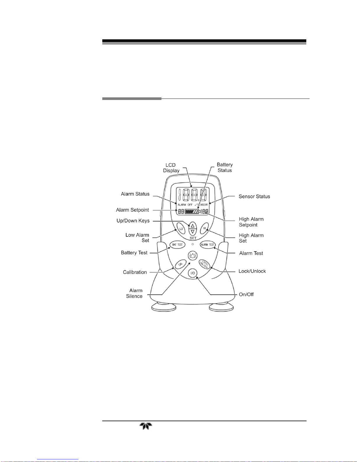
The MX300-I Monitor incorporates a dual concentration alarm with
individual user-defined set points. The set points are displayed on the
lower portion of the LCD display with the low alarm set point appearing
at the lower left and the high alarm appearing on the lower right of the
display. The alarm circuit provides both an audible and a visual alarm.
When the oxygen concentration reaches levels beyond the pre-set
alarm limits, the following will occur:
1. If the HI alarm is triggered because of monitored oxygen level
exceeding the high alarm set point, the green light display will
flash and the alarm buzzer will activate. The alarm buzzer can
be silenced by pressing the Alarm Silence () key.
NOTE: IF THE ALARM CONDITION IS NOT CORRECTED WITHIN
ABOUT 115 SECONDS, THE ALARM BUZZER WILL REAC-
TIVATE. PRESSING THE ALARM SILENCE () KEY
AGAIN WILL SILENCE THE ALARM BUZZER ONCE AGAIN
FOR ABOUT 115 SECONDS, WITH THE BUZZER REAAC-
TIVATING IF THE ALARM CONDITIONS PERSIST.
2. If the LO alarm is triggered because of monitored oxygen level
falling below the low alarm set point, the green light display will
flash and the alarm buzzer will activate.

Portable Oxygen Monitor Introduction
Teledyne Analytical Instruments 3
NOTE: IF THE LOW ALARM CONDITION IS TRIGGERED WITH
THE OXYGEN LEVEL STAYING ABOVE THE SAFETY LIMIT
OF 18%, THE ALARM BUZZER CAN BE DEACTIVATED BY
PRESSING THE ALARM SILENCE () KEY. IF ALARM
CONDITION IS NOT CORRECTED WITHIN ABOUT 115
SECONDS, THE ALARM BUZZER WILL REACTIVATE.
PRESSING THE ALARM SILENCE () KEY AGAIN WILL
SILENCE THE ALARM BUZZER ONCE AGAIN FOR ABOUT
115 SECONDS, WITH THE BUZZER REAACTIVATING IF
THE ALARM CONDITIONS PERSIST.
NOTE: IF THE LOW ALARM CONDITION IS TRIGGERED WITH
THE OXYGEN LEVEL FALLING BELOW 18%, THE
√SENSOR SIGN WILL FLASH ALONG WITH THE GREEN
LIGHT, AND THE BUZZER WILL ACTIVATE. IN THIS CON-
DITION, THE ALARM BUZZER CANNOT BE SILENCED.
WHILE HOLDING DOWN THE ALARM SILENCE () KEY
MAY MOMENTARILY SILENCE THE ALARM BUZZER, AUD-
IBLE ALARM WILL RETURN UPON DISENGAGING THE
ALARM SILENCE () KEY. HOLDING THE KEY FOR
LONGER DURATIONS WILL INITIATE THE “STUCK KEY”
ALARM, WHICH CAN BE DEACTIVATED ONLY VIA REMOV-
ING THE BATTERIES FROM THE ANALYZER. ANALYZER
SHOULD BE RECALIBRATED UP ON REPOWERING.
1.1 Features
The following features are standard on the MX300-I Monitor:
Large easy to read 3½-digit LCD (see options)
Automatic LCD back lighting upon key press
Microprocessor controlled
Up/Down control keys on the front panel
Sensor fail/disconnect alarm indicator (audible and visual)
Two adjustable concentration alarms with user-defined set
points
Alarm Silence () key
2000 operating hours from 3 AA alkaline batteries
Battery status indicator
Battery test function
Stand for upright tabletop deployment

Introduction MX300-I
Teledyne Analytical Instruments 4
Rugged high impact ABS plastic construction
Splash resistant case
Long life class R17MED sensor
0-1 VDC digital output (optional RS-232)
CE marking per EU MDD and CSA approved
1.2 Options
The following options are available for the MX300-I Monitor:
A-Option—2½-digit LCD instead of 3½-digit
NOTE: CONTACT FACTORY FOR MODIFYING YOUR MONITOR FOR 2½-
DIGIT LCD. FOR RS-232 RECONFIGURATION, SEE SECTION 2.1.5.
B-Option—RS 232 digital output instead of 0-1VDC
Universal Pole Mounting Clamp (P/N CP 2345)
V-Mount Pole Clamp (P/N CP 2344)
V-Mount Wall Adapter P/N B 647)
0-1 VDC Interface Cable (P/NB-75554)
RS 232 Interface Cable (P/N B-75555)
1.3 Applications
The MX300-I Monitor is intended for spot checking the concentra-
tion of oxygen in gas mixtures used in applications such as Anesthesia
gas delivery and Respiratory care, and is intended for adult, pediatric
and neonatal populations.
1.4 Operation Summary
The MX300-I Monitor uses Teledyne Analytical Instruments’ Pa-
tented R17MED oxygen sensor. The sensor output is used to determine
the oxygen gas concentration. The data from the sensor is compared to
the alarm values set by the user, and activates the audible and visual
alarms if the oxygen level crosses the threshold values. Sensor
fail/disconnect alarm is incorporated in the Monitor to warn the user of a
sensor problem. TheSENSOR indicator is illuminated on the LCD and
the audible and visual alarms are activated whenever a fault is detected.

Portable Oxygen Monitor Introduction
Teledyne Analytical Instruments 5
The Class R17MED oxygen sensor is a disposable sensor. The sen-
sor has a cathode (sensing electrode), an anode (counter electrode), and
a compatible electrolyte, and is packaged in a small plastic sensor body.
Oxygen entering the sensor reacts with the anode and a proportional cur-
rent is collected at the cathode, which is then converted into a digital
signal and displayed on the LCD screen on the Monitor.
Used with the R17MED sensor is a removable plastic diverter. This
diverter is used to facilitate the transport of gas mixtures through the
sensor. The diverter, packaged separately when shipped, is necessary
when the tee adapter is used to sample gas flowing through a tube.
The diverter is not necessary and should not be used when the sen-
sor is placed directly in a chamber, or when the sensor is used in con-
fined volume analysis, such as incubators and inhalation tents.
The audio alarm is used for both the concentration alarms and the
sensor-disconnect alarm. The user can manually bypass the concentra-
tion alarm for a set amount of time. Pressing the ALARM SILENCE
() key will provide an audible alarm override for 115 seconds. After
that, if the alarm condition still prevails, the audible alarm will resume.
The ALARM SILENCE () key can also be used to interrupt the sen-
sor-disconnect audible alarm.
CAUTION STATEMENTS:
THE R17MED SENSOR CONTAINS A CAUSTIC ELECTRO-
LYTE AND LEAD. DO NOT TRY TO OPEN THE SENSOR
ASSEMBLY. CHECK THE SENSOR PERIODICALLY FOR
LEAKS. IF THE SENSOR IS LEAKING, REPLACE IT. DO
NOT TRY TO REPAIR IT. CONTACT YOUR DISTRIBUTOR
OR TELEDYNE FOR THE MATERIAL SAFETY DATA SHEET
RELATED TO HANDLING AND DISPOSAL OF THE SEN-
SOR.
THE R17MED SENSOR CONTAINS A CAUSTIC ELECTRO-
LYTE, AND IN THE EVENT OF A LEAK, THE ELECTROLYTE
MAY ATTACK CERTAIN MATERIALS IT IS EXPOSED TO,
SUCH AS ALUMINUM. USE PRECAUTION IN YOUR
CHOICE OF INTERFACE MATERIALS.
REMOVE AND SAVE THE DIVERTER WHEN THE SENSOR
IS USED IN CONFINED VOLUME APPLICATIONS.

Introduction MX300-I
Teledyne Analytical Instruments 6
THE MX300-I OXYGEN MONITOR, R17MED OXYGEN SEN-
SOR AND ASSOCIATED HARDWARE ARE INTENDED FOR
USE AS SECONDARY DEVICES TO VERIFY THE CON-
CENTRATION OF OXYGEN IN GAS MIXTURES. DO NOT
USE THESE DEVICES AS PRIMARY LIFE-SUPPORT OR
PRIMARY MONITORING DEVICES.
THE INFORMATION OBTAINED FROM THE MX300-I
SHOULD NEVER BE USED TO ADJUST A LIFE-SUPPORT
SYSTEM. IT SHOULD ONLY BE USED AS AN INDICATION
THAT THE LIFE SUPPORT SYSTEM OR DEVICE IN THE
BREATHING SYSTEM THAT MX300-I IS BEING USED WITH
MAY REQUIRE SERVICE AND/OR CALIBRATION.

Portable Oxygen Monitor Operating Instructions
Teledyne Analytical Instruments 7
Operating Instructions
Notes:
Upon receipt, INSPECT THE ENTIRE UNIT FOR ANY DAMAGE. Check the
unit and all included accessories for broken or loose parts. If damaged, DO NOT
USE. Notify the shipper, your distributor or Teledyne Analytical Instruments.
This equipment is internally powered using 3 AA batteries.
The LOCK/UNLOCK key helps prevent accidental change to the calibration set
point. At least two keys must be pressed in order to modify the critical calibra-
tion set point value.
If the keys are unlocked and no keys are pressed, the Monitor will revert to the
locked mode within nine seconds.
The ALARM SILENCE (
) key and the BAT TEST key continue to operate
normally when the lock feature is activated.
2.1 Setup
To use your MX300-I Monitor, first install the batteries, then install the
oxygen sensor and then, calibrate the Monitor using the steps outlined in section
2.1.4.
2.1.1 Sensor Installation or Replacement
Note: Install the R17MED oxygen sensor before using the MX300-I oxygen Monitor.
1. Remove the new sensor from its protective bag. Inspect the sensor for
damage or electrolyte leakage.
Warning: The sensor has a caustic electrolyte. Do not use a damaged or leaking
sensor. Do not let the electrolyte come in contact with the skin. If it
does, flush affected area with water. Do not attempt to open or repair
the sensor.
Warning: The sensor also contains lead. Leaking or exhausted sensors should be
handled and disposed of in accordance with local regulations.

Operating Instructions MX300-I
Teledyne Analytical Instruments 8
Warning: The MX300-I oxygen Monitor, R17MED oxygen sensor, and associated
hardware are non-sterile devices. Autoclaving or other chemical clean-
ing may damage the Monitor and the sensor.
2. Plug one end of the coiled cable into the receptacle on the back of the
R17MED sensor and secure it in place with the capture nut located at the
base of the connector. See Figure 2-1.
Figure 2-1: Installing the R17MED Sensor
3. Plug the other end of the cable into the receptacle located on the side of the
unit and secure it using the capture nut. See Figure 2-2.
Figure 2-2: Sensor Cable Connection to Monitor
Note: Cable shown is for illustration purposes only.

Portable Oxygen Monitor Operating Instructions
Teledyne Analytical Instruments 9
Note: Do not use the plastic flow diverter with the R17MED sensor when the sensor is
used for diffusion sampling (such as with oxygen tents, incubators, etc.). When
the sensor is used with a Tee Adapter, such as in a breathing system, the diver-
ter must be used as shown in Figure 2-3.
Figure 2-3: Mounting the Sensor in the Tee Adapter
2.1.2 Mounting
The MX300-I can be mounted in several ways depending on the optional
equipment ordered at the time of purchase. See Section 1.3.
2.1.2.1 V-Mount Adapter Installation
The V-Mount Adapter consists of a matching plastic plate with integral V-
grooves that attach to the rear of the Monitor.
Figure 2-4: V-Mount Adapter Installation

Operating Instructions MX300-I
Teledyne Analytical Instruments 10
To install V-Mount Adapter, remove the battery compartment door by pry-
ing up the hinged latch at the bottom of the cover, then slide the adapter plate
into grooves provided in rear case. Replace the battery compartment door and
secure door latch. See Figure 2-4.
Note: The door latch is a tight fit onto the battery cover. Use a coin to gently pry up the
latch.
2.1.2.2 Universal Mounting Clamp Installation
The optional Universal Mounting Clamp comes with a 1/4-20 screw for se-
curing the clamp to the rear of the Monitor. A threaded brass insert is installed on
the back of the Monitor for this purpose. See Figure 2-5.
Figure 2-5: Brass Insert for Universal Mounting Clamp
2.1.3 Battery Installation
Note: Three “AA” alkaline batteries must be installed in the unit before the Monitor will
operate. The unit must be recalibrated and HI/LO alarm set points must be reset
to desired values whenever new batteries are installed.
To install the batteries:
1. Turn the unit off (if it is on).
2. Hold the Monitor face down in the palm of your hand. Use a coin to
pry up the latch that secures the battery compartment door. Remove
the battery compartment door.
CAUTION: IMPROPER INSTALLATION OF THE BATTERIES MAY RESULT IN
DAMAGE TO THE UNIT AND BATTERIES.
Note: Use alkaline batteries only. Other battery types will produce erroneous battery
test readings.

Portable Oxygen Monitor Operating Instructions
Teledyne Analytical Instruments 11
3. Install 3 “AA” alkaline batteries into the holder as shown in Figure 2-
6. Each battery has its own slot. To insure proper polarity, place the
bottom (flat) or negative end of the battery in the end of the holder
marked “–”. Place the top (button) or positive end of the battery in the
end of the holder marked “+”. Do this for each battery.
Figure 2-6: Installing Batteries
4. Re-install the battery compartment door. When the unit is first turned
on, the screen will momentarily display all LCD segments. During
this period, diagnostic tests are being conducted to ensure that the
circuits are functioning correctly. The unit will activate the audible
and visual alarms for about 1 second. The LCD will flash
continuously indicating the unit is in the unlocked position ready for
calibration.
Note: When batteries are first installed or power is lost for any reason, the Monitor
defaults to the calibration mode. All keys except the CAL and ON/OFF (I/O)
keys will be inoperable until a successful calibration is achieved.
5. Note the battery display located below the oxygen readout display. It
continuously shows a bar graph of the remaining life to the batteries.
Using new batteries will illuminate all 5 segments from the left to the
right end of the bar. The bar graph indicator is continuously on when
the Monitor is powered on.
2.1.4 Calibration
The MX300-I should be calibrated before each use and every 8 hours to
maintain accuracy.
When batteries are removed for any reason or when new batteries are in-
stalled, the Oxygen Monitor defaults to the calibration mode with the LCD dis-

Operating Instructions MX300-I
Teledyne Analytical Instruments 12
play flashing 00.0. Only the CAL and ON/OFF (I/O) keys are functional at this
point. Reset the alarm set points after calibrating the Monitor.
Note: For first time and for routine maintenance calibrations, make sure that the sen-
sor and sensor cable are installed correctly before attempting to calibrate the
Monitor.
Figure 2-7: Calibration Sequence
To calibrate the Monitor (See Figure 2-7):
1. Turn the unit on by pressing the ON/OFF (I/O) key.
2. Check the batteries by pressing the BAT TEST key.
3. If the LCD is not flashing, press the LOCK/UNLOCK key to unlock
the keys. LCD will flash indicating that changes can be made to the
settings. If the batteries have just been installed the LCD will flash
00.0
4. As with most oxygen monitors, the highest level of accuracy is
achieved when calibration is conducted using 100% oxygen. After in-
stalling the flow diverter as noted in Section 2.1.1, insert the sensor
into the plastic tee and connect to a supply of pure dry oxygen flow-
ing at 1-2 liters per minute.
Note: An accessory calibration assembly (P/N C53790) is available from Teledyne for
use with the R17MED sensor
5. Wait about 20 seconds to ensure that the sample line is completely
purged with the calibration gas. Press the CAL key. The LCD will
count down from 9 to 0. The Monitor electronics will measure the
sensor output during this countdown to determine the gas concentra-
tion and selects the calibration range of either 100% or 20.9%. When
the calibration is complete, the LCD will display the gas value.
Other manuals for MX300-I
1
Table of contents
Other Teledyne Oxygen Equipment manuals

Teledyne
Teledyne MX300-I User manual

Teledyne
Teledyne 319R User manual

Teledyne
Teledyne 3160 User manual

Teledyne
Teledyne 329R User manual

Teledyne
Teledyne MD300 User manual

Teledyne
Teledyne OT-3 User manual

Teledyne
Teledyne 356WA User manual

Teledyne
Teledyne 3020T User manual

Teledyne
Teledyne MX300 User manual
Popular Oxygen Equipment manuals by other brands

Ozotech
Ozotech Power Prep Phoenix Operation & maintenance manual

C-Aire
C-Aire Companion Series user manual

Kröber
Kröber aeroplus E Instructions for use

EUTECH INSTRUMENTS
EUTECH INSTRUMENTS CYBERSCAN DO 1500 DO METER instruction manual

Maxtec
Maxtec MaxVenturi Maintenance manual

Ozotech
Ozotech EOG 200 Operation & maintenance manual