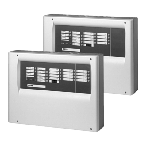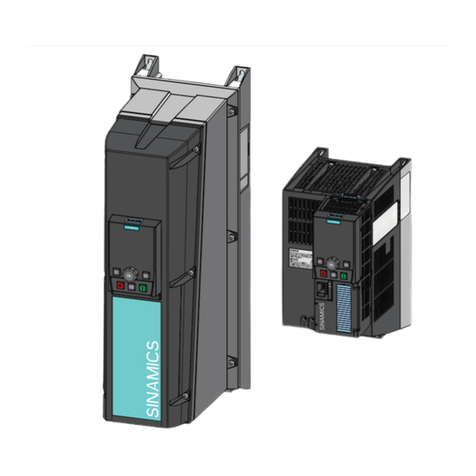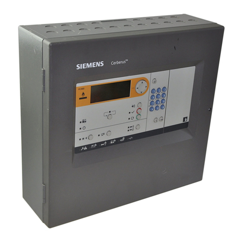
FS20 Marine Fire Detection Control Panel
Siemens Industry, Inc. A6V10519176_enUS_b
Building Technologies Division
9.1 Install Batteries – BP-62.....................................................................................44
9.2 Install Wiring.......................................................................................................46
9.3 Determining the Battery......................................................................................47
10 FCI2016-U1 Periphery Board (252p)...............................................................48
10.1 Description..........................................................................................................48
10.2 Views..................................................................................................................50
10.3 Configuration Input Power and Battery..............................................................52
10.3.1 Wiring Specs....................................................................................................52
10.3.2 X301 Terminal Block – Power Supply 1 ..........................................................52
10.3.3 X305 Jumper – Power Supply On/Off..............................................................53
10.3.4 X303 Battery Terminal .....................................................................................53
11 FCI2017-U1 Periphery Board (504p)...............................................................54
11.1 Description..........................................................................................................54
11.2 Views..................................................................................................................56
11.3 Configuration Input Power and Battery..............................................................58
11.3.1 Wiring Specs....................................................................................................58
11.3.2 X301 Terminal Block – Power Supply 1 ..........................................................58
11.3.3 X305 Jumper – Power Supply 2 On/Off...........................................................59
11.3.4 X303 Battery Terminal .....................................................................................59
12 Periboard Installation, Wiring and Jumpers Set-Up.....................................60
12.1 Installation of the Periphery Board.....................................................................60
12.2 Notification Appliance Circuits............................................................................61
12.2.1 X601 Terminal Block........................................................................................62
12.2.2 X602 Jumper....................................................................................................62
12.2.3 X603 Jumper....................................................................................................62
12.2.4 X604, X605, X606 Jumper...............................................................................63
12.2.5 X403 Jumper....................................................................................................63
12.3 Bell Follower Input..............................................................................................63
12.3.1 Wiring Specs....................................................................................................63
12.4 Auxiliary 24VDC Output .....................................................................................64
12.4.1 Wiring Specs....................................................................................................64
12.4.2 X1001 Auxiliary Output Terminal Block...........................................................64
12.5 Relays.................................................................................................................65
12.5.1 Wiring Specs....................................................................................................65
12.5.2 X1101 Relay Terminal Block ...........................................................................65
12.6 Detector Circuits.................................................................................................66
12.6.1 X1401 and X1801 Terminal Block ...................................................................67
12.6.2 X1402 and X1802 Terminal Block ...................................................................67
12.7 Indicators............................................................................................................68
12.8Reset Buttons.....................................................................................................68
12.8.1 S100 RESET Periphery Board ........................................................................68
12.8.2 S1201 RESET Core ‘A’ Detector Circuit..........................................................68
