Telequipment Serviscope S51A User manual
©)
SERVISCOPE
TYPE
$51
-
All
Telequipment
instruments
are
the
subject
of
continuous
development
and
improvement
and,
_in_
consequence,
may
incorporate
minor
detail
changes
from
the
information
contained
herein.
"Serviscope'
and
'TelequipmenT''
are
registered
trade
marks
of
TELEQUIPMENT
LIMITED
313
Chase
Road
London,
N.14.
Copyright
JUNE
1966

OPERATING
INSTRUCTIONS
SERVISCOPE
TYPE
551
CONTENTS
GENERAL
DESCRIPTION
S51A
/
S51E
/
S51T
FIRST
TIME
OPERATION
Use
of
Controls
Simplified
Method
CIRCUIT
DESCRIPTION
eee
MAINTENANCE
AND
ADJUSTMENT
PROCEDURES
COMPONENTS
LIST
vee
soe
CIRCUIT
DIAGRAMS
see
COMPONENT
LOCATION
PLATES
FRONT
PANEL,
CONTROLS
PRINTED
CIRCUIT
LAYOUT
18
25
28/29

GENERAL
DESCRIPTION
The
S51
Serviscope
is
produced
in
three
versions:
S
51A
~
general
purpose
Oscilloscope.
S
51E
-
simplified
educational
version
with
the
NORMAL/TV
FIELD
switch
and
INT/EXT
switch
both
deleted,
and
the
time
base
always
triggered
by
an
internal
signal.
Also
inthe
S51E
the
sawtooth
voltage
is
brought
out
to
a
terminal
on
the
front
panel
marked
SWEEP
OUTPUT,
at
an
amplitude
of
approxi-
‘mately
20
v
Pto
P.
(The
SWEEP
OUTPUT
terminal
re-
places
the
EXT
TRIG
terminal
on
the
S
514A.)
S
51T
~-
similar
to
the S
51A
but
incorporates
an
additional
Horizont-
al
Pre-Amplifier,
with
a
gain
of
X10.
A
switch
at
the
rear
of
the
instrument
enables
the
Pre-Amplifier
to
be
switched
out,
when
the
S
51T
has
a
performance
and
specification
identical
to
the
S
51A.
With
the
Pre-Amplifier
switched
in,
the
X
Amplifier
gain
is
increased
to
100
mV/cm
and
the
bandwidth
is
DC
to
approximately
10
Kc/s
at
-3dB.
CATHODE
RAY
TUBE
The
5'!
flat
faced
tube
operates
at
3
Kv
overall,
giving
an
extremely
bright
fine
trace
over
the
whole
of
the
working
area
(8
cms.
x
8cms.).
A
Pl
phosphor
is
normally
supplied
but
a
long
persistence
tube
is
available
if
specified.
A
green
filter
improves
the
contrast
under
conditions
of
high
ambient
light.
VERTICAL
DEFLECTION
AMPLIFIER
The
amplifier
consists
of
two
stages.
A
cathode
coupled
input
stage,
the
output
of
which
drives
a
cathode
follower,
and
an
output
stage
consisting
of
a
long
tailed
pair,
the
signal
being
fed
to
one
grid
and
a
DC
shift
voltage
to
the
other
grid.
The
amplifier
has
a
sensitivity
of
100mV/cm
and
a
bandwidth
of
DC
to
3
Mc/s
(-3dB.
approx.).
The
nine-position
input
attenuator
is
frequency
compensated
and
gives
sensitivities
cf
100mV,
200mV, 500mV,
1V,
2V,
5V,
10V,
20V,
50V,
per
cm.
The
input
impedance
is
1
megohm,
shunted
by
about
30
pf.
SWEEP
CIRCUIT
The
sweep
generator
consists
of
a
Miller
run-down
circuit.
Six
preset
sweep
speeds
are
provided
from
1
usec/cm.
to
100Msec/
cm.
A
variable
control
with
a
10:1
range
provides
overlap
between
fixed
ranges
and
reduces
the
slowest
sweep
to
l
sec/cm.
HORIZONTAL
AMPLIFIER
The
X
GAIN
control
expands
the
trace
to
approximately
2
times
and
sufficient
shift
is
provided
to
enable
any
part
of
the
expanded
trace
to
be
positioned
centrally
on
the
screen.
TRACE
UNBLANKING
D.C.
coupling
of
the
unblanking
waveform
gives
uniform
trace
brightness
at
all
sweep
speeds
and
operates
in
such
a
way
that
the
time
base
flyback
is
completely
eliminated.
TRIGGERING
Two
modes
of
triggering
are
provided.
1.
AUTO.
On
this
setting
the
sweep
free
runs
at
a
slow
speed
in
the
absence
of
an
input
signal,
but
will
be
triggered
automatically
as
soon
as
an
input
signal
is
applied.
This
mode
of
operation
can
be
used
for
90%
of
all
normal
laboratory
uses.

2.
TRIGGER
LEVEL
SELECTION.
With
the
AUTO
switch
OFF
the
Trigger
Level
Control
allows
the
sweep
to
be
triggered
at
any
point
on
the
input
waveform.
The
circuit
will
trigger
internally
on
2mm.
of
displayed
signal,
and
externally
(except
$51
E)
from
3v.
peak
to
peak.
T.V.
SYNC
The
built-in
TV
sync
integrator
circuit
(S51A
and
S51T
only)
makes
it
possible
to
trigger
the
sweep
from
the
Frame
pulses
of
a
composite
Television
waveform.
REAR
CONNECTORS
Connectors
on
the
rear
panel
provide
access
to
the
Horizon-
tal
Amplifier
and
intensity
modulation
of
the
beam.
COOLING
The
S51
is
cooled
by
convection.
Air
enters
the
bottom
of
the
case
and
is
drawn
up
past
the
tubes
and
cther
hot
components,
passing
out
through
the
slots
at
the
top.
Do
not
obstruct
the
air
flow
in
any
way.
Do
not
put
anything
on
top
of
the
instrument
and
make
sure
that
there
is
an
air
Space
underneath.
STARILITY
TV
FELD
EXT.
TRIG
aot
FIRST
TIME
OPERATION
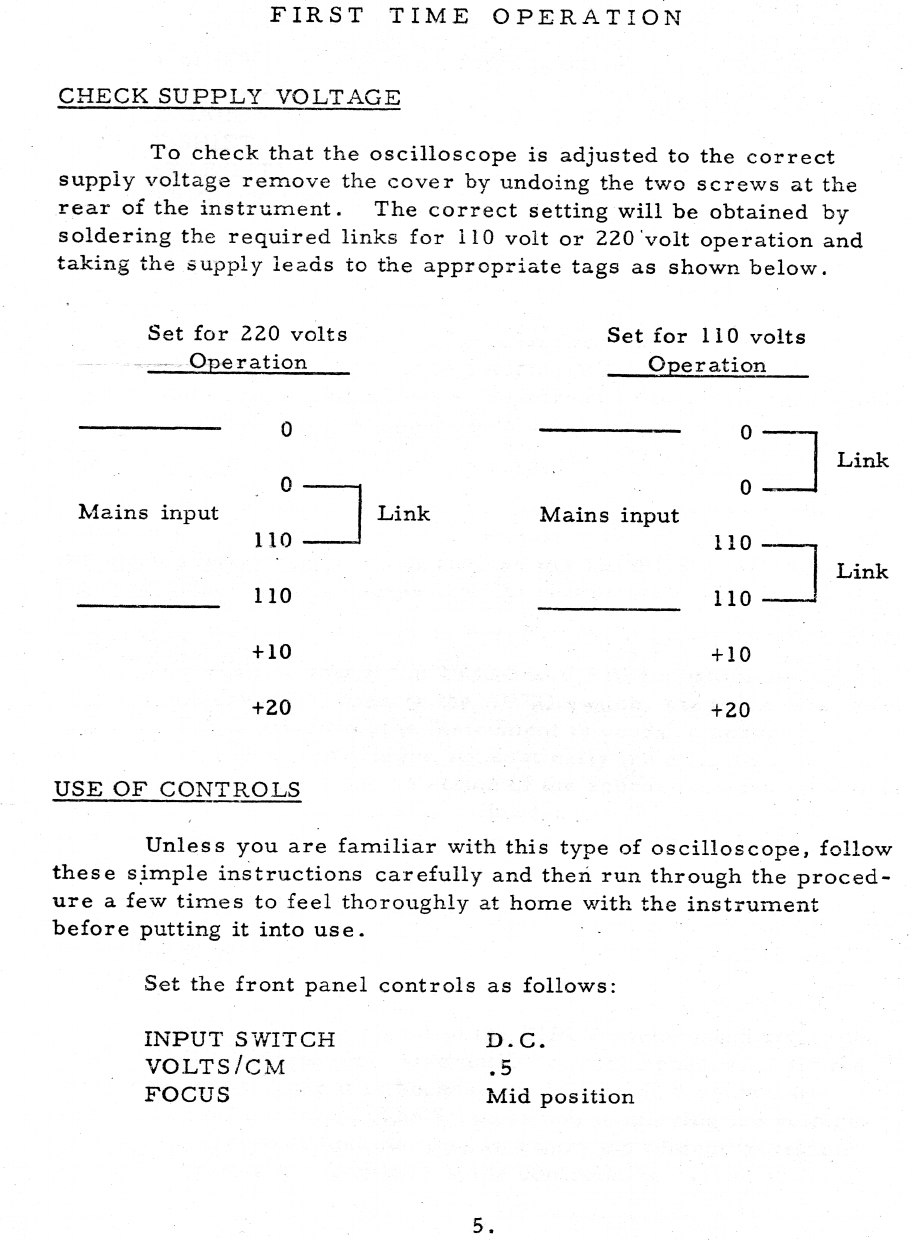
CHECK
SUPPLY
VOLTAGE
To
check
that
the
oscilloscope
is
adjusted
to
the
correct
supply
voltage
remove
the
cover
by
undoing
the
two
screws
at
the
rear
of
the
instrument.
The
correct
setting
will
be
obtained
by
soldering
the
required
links
for
110
volt
or
220'volt
operation
and
taking
the
supply
leads
to
the
appropriate
tags
as
shown
below.
Set
for
220
volts
Set
for
110
volts
~~
Operation
Operation
0
0
Link
o-
o——
Mains
input
Link
Mains
input
110
——
110
————
Link
110
110
——~
+10 +10
+20
+20
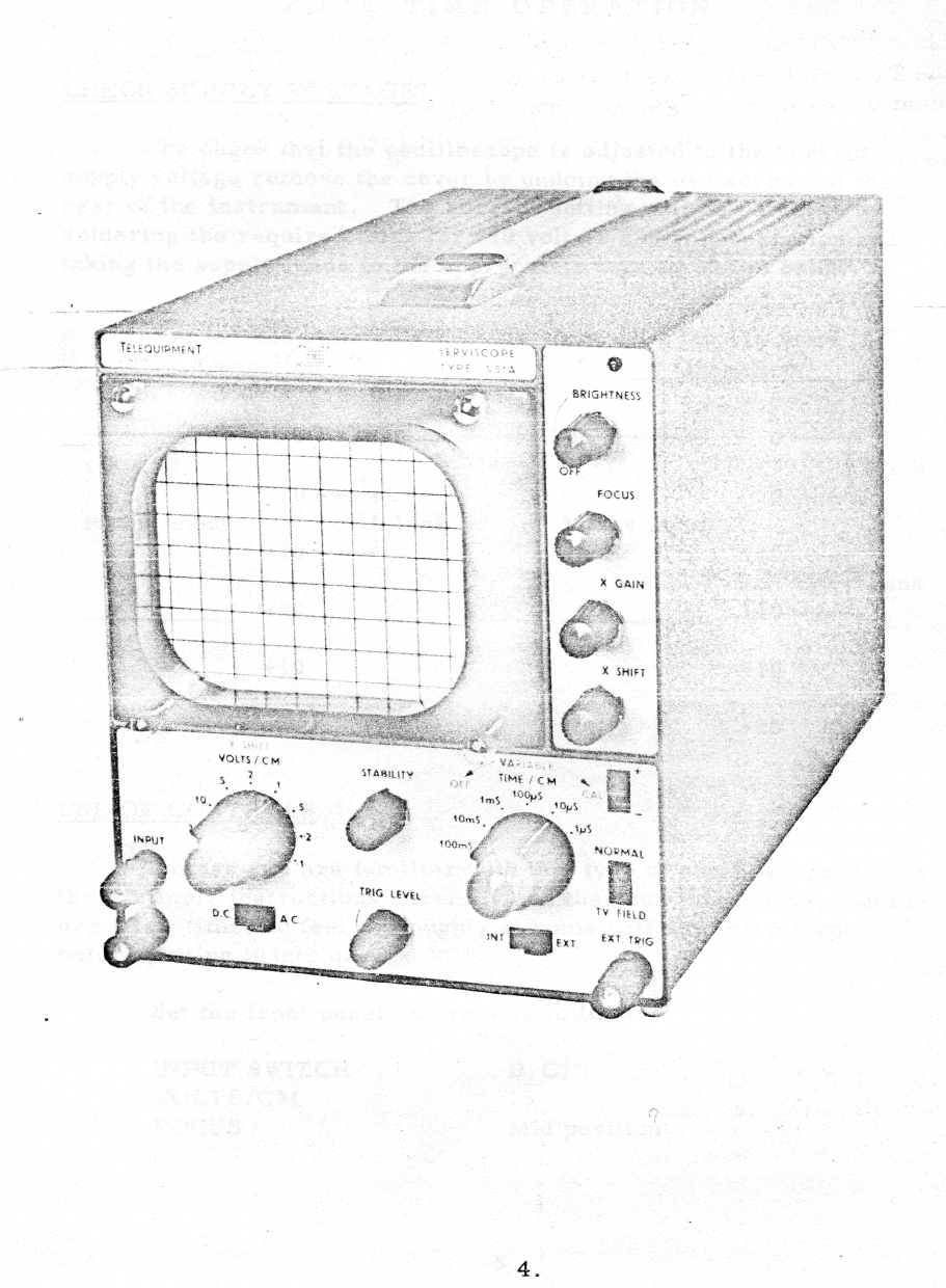
USE
OF
CONTROLS
Unless
you
are
familiar
with
this
type
of
oscilloscope,
follow
these
simple
instructions
carefully
and
then
run
through
the
proced-
ure
a
few
times
to
feel
thoroughly
at
home
with
the
instrument
before
putting
it
into
use.
,
Set
the
front
panel
controls
as
follows:
INPUT
SWITCH
D.C.
VOLTS/CM
.5
FOCUS
Mid
position
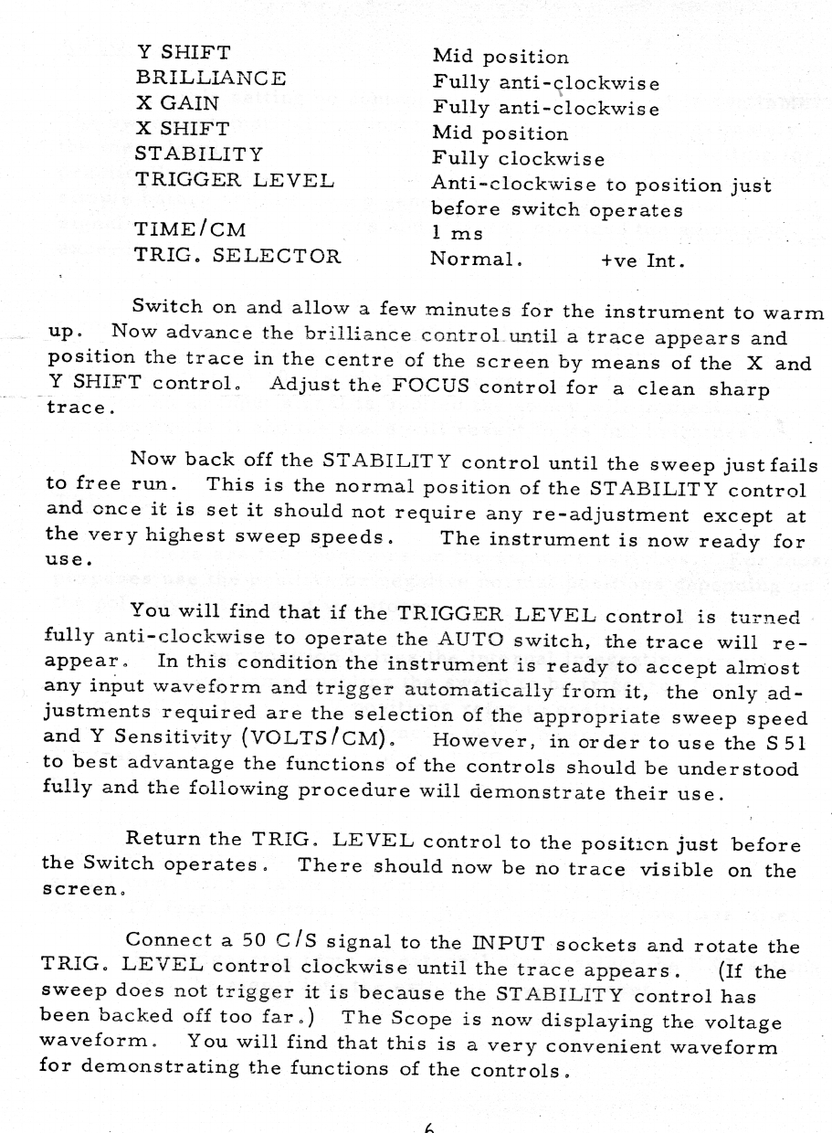
Y
SHIFT
Mid
position
BRILLIANCE
Fully
anti-clockwise
X
GAIN
Fully
anti-clockwise
X
SHIFT
Mid
position
STABILITY
Fully
clockwise
TRIGGER
LEVEL
Anti-clockwise
to
position
just
before
switch
operates
TIME/CM
1
ms
TRIG.
SELECTOR
Normal.
+ve
Int.
Switch
on
and
allow
a
few
minutes
for the
instrument
to
warm
up.
Now
advance
the
brilliance
control
until
a
trace
appears
and
position
the
trace
in
the
centre
of
the
screen
by
means
of
the
X
and
Y
SHIFT
control.
Adjust
the
FOCUS
control
for
a
clean
sharp
trace.
Now
back
off
the
STABILITY
control
until
the
sweep
just
fails
to
free
run.
This
is
the
normal
position
of
the
STABILITY
control
and
once
it
is
set
it
should
not
require
any
re-adjustment
except
at
the
very
highest
sweep
speeds.
The
instrument
is
now
ready
for
use.
You
will find
that
if
the
TRIGGER
LEVEL
control
is
turned
fully
anti-clockwise
to
operate
the
AUTO
switch,
the
trace
will
re-
appear.
In
this
condition
the
instrument
is
ready
to
accept
almost
any
input
waveform
and
trigger
automatically
from
it,
the
only
ad-
justments
required
are
the
selection
of
the
appropriate
sweep
speed
and
Y
Sensitivity
(VOLTS/CM).
However,
in
order
to
use
the
S51
_
to
best
advantage
the
functions
of
the
controls
should
be
understood
fully
and
the
following
procedure
will
demonstrate
their
use.
Return
the
TRIG.
LEVEL
control
to
the
position
just
before
the
Switch
operates.
There
should
now
be
no
trace
visible
on
the
screen.
Connect
a
50
C/S
signal
to
the
INPUT
sockets
and
rotate
the
TRIG.
LEVEL
control
clockwise
until
the
trace
appears.
(If
the
sweep
does
not
trigger
it
is
because
the
STABILITY
control
has
been
backed
off
too
far.)
The
Scope
is
now
displaying
the
voltage
waveform.
You
will
find
that
this
is
a
very
convenient
waveform
for
demonstrating
the
functions
of
the
controls.
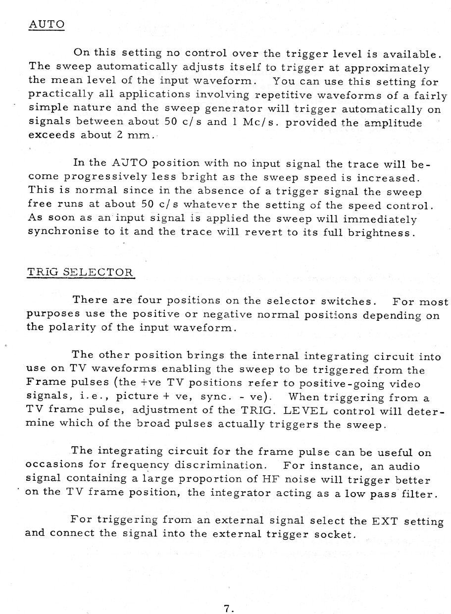
AUTO
On
this
setting
no
control
over
the
trigger
level
is
available.
The
sweep
automatically
adjusts
itself
to
trigger
at
approximately
the
mean
level
of
the
input
waveform.
You
can
use
this
setting
for
practically
ail
applications
involving
repetitive
waveforms
of
a
fairly
simple
nature
and
the
sweep
generator
will
trigger
automatically
on
signals
between
about
50
c/s
and
1
Mc/s.
provided
the
amplitude
exceeds
about
2
mm..
In
the
AUTO
position
with
no
input
signal
the
trace
will
be-
come
progressively
less
bright
as
the
sweep
speed
is
increased.
This
is
normal
since
in
the
absence
of
a
trigger
signal
the
sweep
free
runs
at
about
50
c/s
whatever
the
setting
of
the
speed
control.
As
soon
as
an
input
signal
is
applied
the
sweep
will
immediately
synchronise
to
it
and
the
trace
will
revert
to
its
full
brightness.
TRIG
SELECTOR
There
are
four
positions
on
the
selector
switches.
For
most
purposes
use
the
positive
or
negative
normal
positions
depending
on
the
polarity
of
the
input
waveform.
The
other
position
brings
the
internal
integrating
circuit
into
use
on
TV
waveforms
enabling
the
sweep
to
be
triggered
from
the
Frame
pulses
(the
+ve
TV
positions
refer
to
positive-going
video
signals,
i.e.,
picture
+
ve,
sync.
-
ve).
When
triggering
from
a
TV
frame
pulse,
adjustment
of
the
TRIG.
LEVEL
control
will
deter-
mine
which
of
the
broad
pulses
actually
triggers
the
sweep.
The
integrating
circuit
for
the
frame
pulse
can
be
useful
on
occasions
for
frequency
discrimination.
For
instance,
an
audio
signal
containing
a
large
proportion
of
HF
noise
will
trigger
better
‘on
the
TV
frame
position,
the
integrator
acting
as
a
low
pass
filter.
For
triggering
from
an
external
signal
select
the
EXT
setting
and
connect
the
signal
into
the
external
trigger
socket.

X-GAIN
and
X-SHIFT
With
the
X-GAIN
control
in
the
minimum
(anti-clockwise)
position,
the
trace
will
be
approximately
8
cm.
long
and
the
X-SHIFT
control
should
be
used
to
centre
this
trace about
the
10
x
8
cm.
ruled
graticule.
Increasing
the
X-GAIN
control
expands
the
trace about
the
centre
of
the
screen
up
to
a
maximum
of
X2
and
the
X-SHIFT
control
is
then
used
to
position
the
required
portion
of
this
trace
on
the
screen.
It
should
be
noted
that
the
time
calibration
only
holds
good
at
the
minimum
setting
of
the
X-GAIN
control.
If
you
wanttomeasure
time
intervals
at
any
other
setting
the
speed
must
be
standardised
at
this
setting.
VOLTS
PER
CM.
This
is
a
nine-position
switch
which
inserts
a
series
of
fre-
quency
compensated
resistance
dividers
between
the
input
socket
and
the
Vertical
Amplifier.
Normally
this
is
used
merely
to
obtain
a
picture
of
convenient
height,
but
if
the
gain
of
the
Amplifier
is
standardised,
direct
readings
of
the
input
voltage
can
be
made.
D.C./A.C.
SWITCH
On
the
A.C.
position
this
switch
inserts
a
blocking
capacitor
in
series
with
the
input
of
the
Vertical
Amplifier
removing
the
D.C.
component
of
the
signal.
This
is
the
condition
in
which
the
$51
will
normally
be
used
unless
it
is
specifically
required
to
include
the
D.C.
component
or
to
use
the
instrument
on
very
low
frequency
sig-
nals.
The
time
constant
of
the
input
circuit
on
the
A.C.
position
is
such
that
the
response
is
3
dB
down
at
2
cycles,
which,
while
adequate
for
all
normal
purposes,
may
limit
the
application
in
some
instances.
For
example,
you
will
notice
that
on
a
50
cycle
square-
Wave
a
pronounced
tilt
occurs
on
the
A.C.
position.
If
a
longer
time
constant
is
required,
a
higher
capacity
external blocking
capa-
citor
must
be
used
with
the
input
switch
set
to
D.C.

REAR
CONNECTORS
1.
X-Amp
Input.
This
socket
provides
an
access
to
the
input
of
the
Horizontal
Deflection
Amplifier
and
is
suitable
for
signals
between
about
4
and
10
volts
p.p.
The
X-GAIN
control
gives
about
a
2 to
1
variation
of
gain.
When
using
the
X-Amplifier
the
sweep
can
be
stopped
by
turning
the
VARIABLE
SPEED
control
fully
anti-
clockwise.
The
input
impedance
is
about
500
K
and
the
input
capa-
city
about
100
pf.
The
frequency
response
is
3
dB
down
at 5
cycles
and
at
about
200
Kc/s.
-2s—-Z.-Mod.
This
socket
is
connected
via
a
blocking
capacitor
to
the
cathode
of
the
CRT.
Thus,
a
negative
pulse
will
brighten
the
trace.
The
time
constant
of
this
circuit
is
.01
mf
and
10,
000ohms.
SIMPLIFIED
METHOD
In
the
above
instructions
the
functions
of
controls
have
been
explained
in
some
detail
so
that
the
engineer
using
the
S51
may
fully
appreciate
its
capacities
and
the
method
of
function.
There
will,
however,
be
a
large
number
of
users
who
will
not
require
all
the
facilities
provided
and
to
whom
simplicity
of
operation
is
of
major
importance.
The
following
simplified
instructions
will
suffice
for
most
applications,
in
fact
for
any
application
where
the
older
type
of
Oscilloscope
could
be
used
the
following
method
will
provide
better
results
much
more
quickly
and
simply.
Set
input
switch
to
A.C.
Switch
on
and
allow
a
few
minutes
to
warm
up.
Turn
STABILITY
control
fully
clockwise
and
adjust
BRILLIANCE
and
FOCUS
controls
for
a
sharp
trace.
Back
off
STABILITY
control
until
the
TIME
BASE
stops.
The
STABILITY
control
once
set
should
not
require
any
further
adjust-
ment.
The
instrument
is
now
set
for
use.

For
most
applications
switch
to
AUTO,
connect
input
signai,
and
adjust
VOLTS/CM
switch
to
give
a
convenient
size
trace.
Use
TIME/CM
and
VARIABLE
as
coarse
and
fine
frequency
controls
to
suit
the
input
signal.
For
T.V.
waveforms
use
T.V.
FIELD
position
(S51A
and
S51T
only).
If
the
sweep
fails
to
lock,
the
STABILITY
control
has
been
turned
up
too
far.
For
some
input
waveforms
and
sometimes
for
T.V.
wave-
forms
it
may
be
necessary
to
adjust
the
TRIG.
LEVEL
control
rather
than
to
use
the
AUTO
position.
10.

For
most
applications
switch
to
AUTO,
connect
input
signai,
and
adjust
VOLTS/CM
switch
to
give
a
convenient
size
trace.
Use
TIME/CM
and
VARIABLE
as
coarse
and
fine
frequency
controls
to
suit
the
input
signal.
For
T.V.
waveforms
use
T.V.
FIELD
position
(S51A
and
S51T
only).
If
the
sweep
fails
to
lock,
the
STABILITY
control
has
been
turned
up
too
far.
For
some
input
waveforms
and
sometimes
for
T.V.
wave-
forms
it
may
be
necessary
to
adjust
the
TRIG.
LEVEL
control
rather
than
to
use
the
AUTO
position.
10.
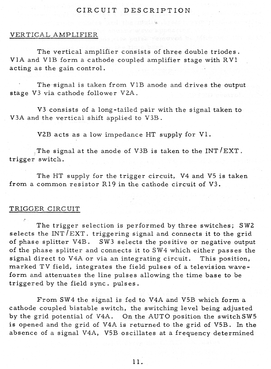
CIRCUIT
DESCRIPTION
VERTICAL
AMPLIFIER
The
vertical
amplifier
consists
of
three
double
triodes.
V1A
and
V1B
form
a
cathode
coupled
amplifier
pee
with
RV}!
acting
as
the
gain
control.
The
signal
is
taken
from
V1B
anode
and
drives
the
output
stage
V3
via
cathode
follower
V2A.
V3
consists
of
a
tas
-tailed
pair
with
the signal
taken
to
V3A
and
the
vertica
ift
applied
to
V3B.
V2B
acts
as
a
low
impedance
HT
supply
for
Vl.
The
signal
at
the
anode
of
V3B
is
taken
to
the
INT/EXT.
trigger
switch.
The
HT
supply
for the
trigger
circuit,
V4
and
V5
is
taken
from
a
common
resistor
R19
in
the
cathode
circuit
of
V3.
TRIGGER
CIRCUIT
The
trigger
selection
is
performed
by
three
switches;
SW2
selects
the
INT/EXT.
triggering
signal
and
connects
it
to
the
grid
of
phase
splitter
V4B.
SW3
selects
the
positive
or
negative
output
of
the
phase
splitter
and
connects
it
to
SW4
which
either
passes
the
signal
direct
to
V4A
or
via
an
integrating
circuit.
This
position,
marked
TV
field,
integrates
the
field
pulses
of
a
television
wave-
form
and
attenuates
the
line
pulses
allowing
the
time base
to
be
triggered
by
the
field
sync.
pulses.
From
SW4
the
signal
is
fed
to
V4A
and
V5B
which
form
a
cathode
coupled
bistable
switch,
the
switching
level
being
adjusted
by
the
grid
potential
of
V4A.
Onthe
AUTO
position
the
switchSW5
is
opened
and
the
grid
of
V4A
is
returned
to
the
grid
of
V5B.
In
the
absence
of
a
signal
V4A,
V5B
oscillates
at
a
frequency
determined
ll.
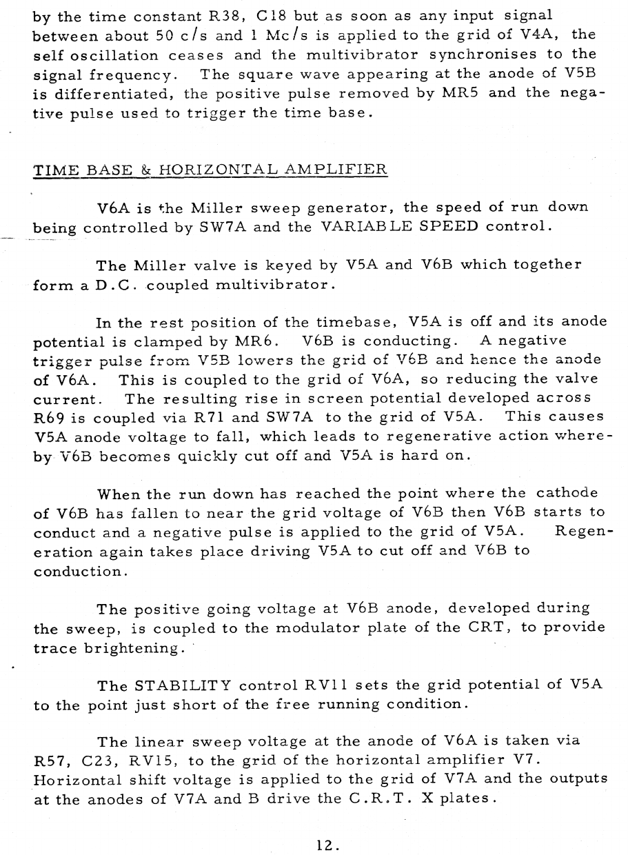
by
the
time
constant
R38,
C18
but
as
soon
as
any
input
signal
between
about
50
c/s
and
1
Mc/s
is
applied
to
the
grid
of
V4A,
the
self
oscillation
ceases
and
the
multivibrator
synchronises
to
the
signal
frequency.
The
square
wave
appearing
at
the
anode
of
V5B
is
differentiated,
the
positive
pulse
removed
by
MR5
and
the
nega-
tive
pulse
used
to
trigger
the
time
base.
TIME
BASE
&
HORIZONTAL
AMPLIFIER
V6A
is
the
Miller
sweep
generator,
the
speed
of
run
down
being
controlled
by
SW7A
and
the
VARIABLE
SPEED
control.
The
Miller
valve
is
keyed
by
V5A
and
V6B
which
together
form
aD.C.
coupled
multivibrator.
In
the
rest
position
of
the
timebase,
V5A
is
off
and
its
anode
potential
is
clamped
by
MR6.
V6B
is
conducting.
A
negative
trigger
pulse
from
V5B
lowers
the
grid
of
V6B
and
hence
the
anode
of
V6A.
This
is
coupled
to
the
grid
of
V6A,
so
reducing
the
valve
current.
The
resulting
rise
in
screen
potential
developed
across
R69
is
coupled
via
R71
and
SW7A
tothe
grid
of
V5A.
This
causes
V5A
anode
voltage
to
fall,
which
leads
to
regenerative
action
where-
by
V6B
becomes
quickly
cut
off
and
V5A
is
hard
on.
When
the
run
down
has
reached
the
point
where
the
cathode
of
V6B
has
fallen
to
near
the
grid
voltage
of
V6B
then
V6B
starts
to
conduct
and
a
negative
pulse
is
applied
to
the
grid
of
V5A.
Regen-
eration
again
takes
place
driving
V5A
to
cut
off
and
V6B
to
conduction.
The
positive
going
voltage
at
V6B
anode,
developed
during
the
sweep,
is
coupled
to
the
modulator
plate
of
the
CRT,
to
provide
trace
brightening.
~
The
STABILITY
control
RV11
sets
the
grid
potential
of
V5A
to
the
point
just
short
of
the
free
running
condition.
The
linear
sweep
voltage
at
the
anode
of
V6A
is
taken
via
R57,
C23,
RV15,
to
the
grid
of
the
horizontal
amplifier
V7.
Horizontal
shift
voltage
is
applied
to
the
grid
of
V7A
and
the
outputs
at
the
anodes
of
V7A
and
B
drive
the
C.R.T.
X
plates.
12.

Transistor
TRI!
in
the
common
cathode
circuit,
acts
as
a
constant
current
source
and
provides
a
baianced
output
at
the
two
anodes.
An
external
signal
can
be
applied
to
the
grid
of
V7B
through
a
connector
at
the
rear
of
the
instrument.
In
this
condition
the
time
base
should
be
switched
off
with
the
VARIABLE
SPEED
‘control.
POWER
SUPPLY
Silicon
rectifiers
MR1
and
MR2
in
a
voltage
doubling
circuit
supply
the
various
HT
voltages
via
smoothing
resistors
R12
and
-
R22.
The
negative
high
voltage
supply
for the
C.R.T.
is
derived
from
the
secondary
of
the
power
transformer
via
MR4.
MR4
also
supplies
the
negative
supply
to
the
STABILITY
control.
The
positive
high
voltage
supply
is
derived
from
MR3,
the
negative
side
of
the
reservoir
condenser
C10
being
returned
to
the
HT
+ve
supply.
C.R.T.
Intensity
modulation
signals
can
be
supplied
tc
the
cathode
-of
the
C.R.T.
via
C9,
via
a
terminal
on
the
rear
of
the
instrument.
Approximately
15
volts,
negative
going
signals
are
required.
RV7
provides
preset
adjustment
for
ASTIG
setting
and
RV6
.
BLKG
allows
the
stationary
bright
spot
to
be
adjusted
to
a
maxi-
mum
by
varying
the
Al
potential.
13.
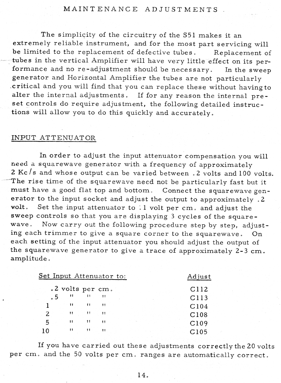
MAINTENANCE
ADJUSTMENTS
The
simplicity
of
the
circuitry
of
the
$51
makes
it
an
extremely
reliable
instrument,
and
for
the
most
part
servicing
will
be
limited
to
the
replacement
of
defective
tubes.
Replacement
of
_tubes
in
the
vertical
Amplifier
will
have
very
little
effect
on
its
per-
formance
and
no
re-adjustment
should
be
necessary.
In
the
sweep
generator
and
Horizontal
Amplifier
the
tubes
are
not
particularly
critical
and
you
will
find
that
you
can
replace
these
without
having
to
alter
the
internal
adjustments.
If
for
any
reason
the
internal
pre-
set
controls
do
require
adjustment,
the
following
detailed
instruc-
tions
will
allow
you
to
do
this
quickly
and
accurately.
INPUT
ATTENUATOR
In
order
to
adjust
the
input
attenuator
compensation
you
will
need
a
squarewave
generator
with
a
frequency
of
approximately
2
Kc/s
and
whose
output
can
be
varied
between
.2
volts
and
100
volts.
~The
rise
time
of
the
squarewave
need
not
be
particularly
fast
but
it
must
have
a
good
flat
top
and
bottom.
Connect
the
squarewave
gen-
erator
to
the
input
socket
and
adjust
the
output
to
approximately
.2
volt.
Set
the
input
attenuator
to
:1
volt
per
cm.
and
adjust
the
sweep
controls
so
that
you
are
displaying
3
cycles
of
the
square-
wave.
Now
carry
out
the
following
procedure
step
by
step,
adjust-
ing
each
trimmer
to
give
a
square
corner
to
the
squarewave.
On
each
setting
of
the
input
attenuator
you
shouid
adjust
the
output
of
the
squarewave
generator
to
give
a
trace
of
approximately
2-3
cm.
amplitude.
Set
Input
Attenuator
to:
Adjust
22
volts
per
cm.
Cl1l2
i
mous
C113
"!
tt Wt
C104
!
tt
W
C108
C109
"
moo"
C105
OWN
1
If
you
have
carried
out
these
adjustments
correctly
the
20
volts
per
cm.
and
the
50
volts
per
cm.
ranges
are
automatically
correct.
In
order
to
adjust
the
capacitors
C102
and
C103
it
is
necessary
to
use
the
high
impedance
probe
as
these
two
capacitors
only
affect
compensation
when
this
probe
is
inuse.
Remove
the
squarewave
generator
from
the
input
socket
and
plug
in
the
high
impedance
probe,
connect
the
output
of
the
squarewave
generator
to
the
probe
tip
and
set the
input
attenuator
to
.1
volt
per
cm.,
set
the
output
of
the
sSquarewave
generator
to
give
approximately
2
cm.
amplitude
and
ad-
just
the
probe
trimmer
(this
is
accessible
through
the
hole
in
the
probe
body)
to
give
a
flat
top
to
the
squarewave,
now
switch
the
input
attenuator
to
the
1
volt
per
cm.
range,
re-adjust
the
output
of
the
squarewave
generator
and
adjust
C2,
set
the
input
attenuator
to
the
10
volts
per
cm.
range
and
adjust
C3.
All
other
ranges
wili
auto-
matically
be
correct.
VERTICAL
AMPLIFIER
Adjustment
of
the
high
frequency
compensation
of
the
vertical
amplifier
shouid
oniy
be
carried
out
if
you
have
at
your
disposal
a
squarewave
generator
which
is
capable
of
producing
an
accurate
Squarewave
at
a
frequency
of
about
250
Kc/s
with
a
rise
time
less
than
100
millimicroseconds
and
which
is
known
to
be
absolutely
free
from
ring
or
overshoot.
The
compensation
circuits
in
the
vertical
amplifier
are
extremely
stable
and
unless
such
a
generator
is
avail-
able
you
would
be
wise
not
to
attempt
any
readjustment..
Set
the
input
attenuator
switch
to
.1
volt
per
cm.
and
adjust
the
output
of
the
squarewave
generator
to
give
a
trace
of
approxima-
tely
2-3
cm.
amplitude
(the
output
frequency
on
the
generator
should
be
between
200
and
300
Kc/s).
The
variable
Ll
is
adjusted
to
give
a
flat
topped
squarewave
with
a
fast
rise
time,
square
corners
and
no
overshoot.
The
only
other
variable
on
the
vertical
amplifier
is
the
set
GAIN
control.
TRIGGER
CIRCUIT
The
only
adjustment
necessary
in
the
TRIGGER
circuit
is
an
occasional
setting
of
the
TRIGGER
sensitivity
control
RV9;
this

should
be
set
so
that
the
TRIGGER
circuit
will
operate
when
the
trace
amplitude
on
the
screen
exceeds
2mm.
If
any
attempt
is
made
to
increase
the
sensitivity
beyond
this
point
erratic
operation
will
almost
inevitably
result.
Connect
a
signal,
say
a
2
Kels
square
wave
to
the
input.
Now
set
the
input
attenuator
to
give
a
trace
2
mm.
high
and
adjust
the
TRIGGER
sensitivity
control
so
that
_at
a
critical
setting
of
the
TRIG.
LEVEL
control
the
sweep
will
just
trigger;
now
reduce
the
trace
amplitude
to
1
mm.
and
make
sure
that
the
sweep
will
not
trigger
on
this
signal.
SWEEP
GENERATOR
&
HORIZONTAL
AMPLIFIER
To
make
a
complete
readjustment
of
the
Sweep
Generator
and
_
Horizontal
Amplifier,
carry
out
the
following
procedure:-
Remove
the
lead
to
the
Moduiator
Anode,
pin
7
on
the
CRT.
Set
the
TIME/CM
switch
to
100
usecs.
Now
advance
the
BRILLIANCE
control
until
you
can
see
the
spot
at
the
beginning
of
the
trace
and
you
will find that
by
adjusting
C23
you
will
be
able
to
make
a
small
"tail''
appear
to
one
side
of
the
spot
or
the
other.
The
correct
setting
for
C23
is
the
point
at
which
this
"tail"
just
disappears
into
the
spot.
Reconnect
the
lead
to
the
Modulator
Anode
on
the
CRT.
Now
set
the
TIME/CM
switch
to
100
usecs
and
the
VARIABLE
speed
to
the
cal.
position.
The
X-GAIN
should
be
at
minimum
and
the
trace
centred
using
the
X-SHIFT
control.
Connect
an
accurately
known
i100
usec.
pulse
repetition
frequency
(19
Kce/s)
to
the
input
terminals
and
adjust
RV15
so
that
the
TIME/CM
is
correct.
Adjustment
of
RV15
will
cause
the
trace
to
move
horizontally
so
it
should
always
be
recentred
using
the
_X-SHIFT
control.
For
greatest
accuracy,
the
calibration
of
the
TIME/CM
should
be
carried
out,
using
the
centre
4
cms.
ofhorizon-
tal
trace.
16,

CRT
CIRCUIT
The
Cathode
Ray
Tube
used
in
the
S51
is
equipped
with an
inter-deflector
plate
shield.
This
is
returned
to
HTi
via
a
1
meg-
ohm
preset
RV8.
This
is
adjusted
in
order
to
ensure
that
the
inter
plate
shield
is
at
the
average
potential
of
the
deflector
plates.
Variation
of
the
inter
plate
shield
voltage
serves
to
correct
pin
cushion
and
barrel
pattern
distortion.
This
control
is
set
during
test.
No
further
adjustment
should
be
necessary
unless
the
tubeis
changed.
HIGH
IMPEDANCE
PROBE
The
adjustment
of
the
probe
compensation
is
best
carried
out
with
a
squarewave
generator
with
an
output
frequency
of
approxima-
tely
1
Kc/s.
The
compensation
trimmer
is
accessible
through
the
hole
in
the
body
of
the
probe
and you
should
adjust
this
to
give
a
Square
corner
to
the
squarewave,
17,
This manual suits for next models
3
Table of contents
Other Telequipment Test Equipment manuals


