manuals.online logo
Brands
  1. Home
  2. •
  3. Brands
  4. •
  5. Bosch
  6. •
  7. Industrial Equipment
  8. •
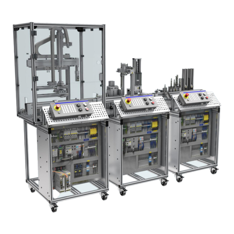
  9. Bosch Rexroth TS 2plus User manual

Bosch Rexroth TS 2plus User manual

中 文 DEUTSCH
ENGLISH
3 842 546 257/2012-07
Replaces: 2006-01
DE+EN+ZH
Montageanleitung • Assembly instructions • 安装说明
Gurtmontage auf Förderstrecken
Belt mounting on conveyor sections
输送段上的皮带安装
2/28 Bosch Rexroth AG TS 2plus | 3 842 546 257/2012-07
Inhalt!
Contents
目录
Safety instructions
1. Notes on assembly
2. Tools and aids
2.1 Tool kit
2.2 Expendable materials
3. Preparation
3.1 Belt length calculation
3.2 Beveling tool - Safety instructions
3.3 Checking the beveling tool
3.4 Beveling the belt ends
4. Belt mounting
4.1 Inserting the belt
4.2 Tensioning of the belt
5. Bonding
5.1 Bonding preparation
5.2 Bonding procedure
Beveling tool
- Initial operation
- Maintenance
- Setting
Sicherheitshinweise
1. Erläuterungen zum Montagevorgang
2. Werkzeuge und Hilfsmittel
2.1 Werkzeugsatz
2.2 Verbrauchsmaterial
3. Vorbereitung
3.1 Berechnung der Gurtlänge
3.2 Ausschärfeinrichtung - Sicherheits-
hinweise
3.3 Prüfen der Ausschärfeinrichtung
3.4 Ausschärfen der Gurtenden
4. Gurtmontage
4.1 Auflegen des Gurtes
4.2 Spannen des Gurtes
5. Kleben
5.1 Vorbereitung
5.2 Klebevorgang
Ausschärfeinrichtung
- Inbetriebnahme
- Wartung
- Einstellung
安全说明
1. 安装步骤说明
2. 工具和辅具
2.1 工具套件
2.2 使用材料
3. 准备
3.1 计算皮带长度
3.2 皮带打磨工具–安全说明
3.3 检查皮带打磨工具
3.4 皮带端头打磨
4. 皮带安装
4.1 铺设皮带
4.2 张紧皮带
5. 粘皮带
5.1 准备
5.2 粘贴过程
皮带打磨工具
- 初次运行
- 保养
- 调节
3 842 546 257/2012-07 | TS 2plus Bosch Rexroth AG 3/28
Sicherheitshinweise!
Safety instructions!
安全说明!

Installation, initial operation, maintenance
and repair work may only be carried out
in accordance with the relevant safety
instructions and regulations and only by
qualified and specially trained personnel!
All electrical connections must be
made in accordance with the applicable
national regulations. For Germany this
is: regulation VDE 0100 of the German
Association of Electricians (VDE)!
Always disconnect the energy supply
(main switch, pressure relief valve, etc.)
prior to any maintenance or repair work!
Precautions should be taken to prevent
inadvertent power restoration, such as
placing a suitable warning sign at the
main switch, e.g. “Maintenance work in
progress” or “Repair work in progress”!
Liability:
In no event can the manufacturer accept
warranty claims or liability claims for
damages arising from improper use of
the appliance or from intervention in the
appliance other than that described in
this instruction manual.
Exclusion of warranty:
The manufacturer can accept no
guarantee claims if non-original
replacement parts have been used!
Part numbers for suitable spare parts
can be found on our “MTparts” CD-
ROM 3 842 529 770.
Environmental protection:
Always observe the manufacturer’s
safety instructions and directions for
disposal when working with solvents!
Always dispose of damaged parts in the
correct manner when replacement work
is complete!

安装、初次运行、保养和维修工作只允
许在遵守安全说明和安全规定的前提
下,由经过培训的专业人员来完成!
电气连接按照相应的国家规定来完成。
对于德国: VDE 0100 规定 (VDE:德
国电气工程师协会)!
在进行所有的维修和保养工作之前,必
须切断所有的能源供给 (主开关、减压
阀等等)!
另外,还必须采取相应的措施防止意外
重新接通,例如,在主开关旁加上“正
在进行保养工作”、“正在进行维修工
作”等警告牌!
责任:
对于由于不正确使用或用户没有遵守使
用说明对产品进行改动而造成的损坏,
制造商不承担任何保修和赔偿责任。
保修:
如果不使用原装备件,制造商不承担任
何保修责任!
适用的备件订货号请在我们的 CD-ROM
“MTpart”3 842 529 770 上查找。
环保:
在使用溶剂工作时,请注意制造商关于
安全和环保方面的相关规定!
在更换损坏件时,必须对换下的零部件
按规定进行环保处理!

Die Installation, Inbetriebnahme,
Wartung und Instandsetzung,
darf nur unter Berücksichtigung
aller Sicherheitshinweise und
-Vorschriften und nur durch geschultes,
eingewiesenes Fachpersonal
durchgeführt werden!
Elektrische Anschlüsse nach der
entsprechenden nationalen Vorschrift.
Für Deutschland: VDE-Vorschrift
VDE 0100!
Vor allen Instandsetzungs-,
und Wartungsarbeiten sind die
Energiezuführungen (Hauptschalter,
Druckminderventil etc.) abzuschalten!
Außerdem sind Massnahmen
erforderlich, um ein unbeabsichtigtes
Wiedereinschalten zu verhindern, z.B.am
Hauptschalter ein entsprechendes
Warnschild “Wartungsarbeiten”,
“Instandsetzungsarbeiten” etc.
anbringen!
Haftung:
Bei Schäden, die aus nicht
bestimmungsgemässer Verwendung und
aus eigenmächtigen, in dieser Anleitung
nicht vorgesehenen Eingriffen entstehen,
erlischt jeglicher Gewährleistungs- und
Haftungsanspruch gegenüber dem
Hersteller.
Garantieausschluss:
Bei Nichtverwendung von
Originalersatzteilen erlischt der
Garantieanspruch!
Die Bestellnummern geeigneter
Ersatzteile finden Sie auf unserer CD-
ROM „MTparts“ 3 842 529 770.
Umweltschutz:
Bei Arbeiten mit Lösungsmitteln
Sicherheits- und Entsorgungsvor-
schriften des Herstellers beachten!
Beim Austausch von Schadteilen ist
auf eine sachgerechte Entsorgung zu
achten!
DEUTSCH
ENGLISH
中 文
515211 -0 2. ep s
515211-01.eps
4/28 Bosch Rexroth AG TS 2plus | 3 842 546 257/2012-07

Zweck des Ausschärfens
Die Dicke des Fördermediums darf an
der Klebestelle nicht größer werden.
Dazu müssen die beiden mit einer Über-
lappung zu verklebenden Gurtenden
durch Abschleifen “dünner gemacht”
werden. Dies wird allgemein als “Aus-
schärfen” bezeichnet.
1. Erläuterungen zum Montagevorgang
Notes on assembly
对安装步骤的说明

Purpose of beveling
The belt must remain the same thickness
where it is bonded as along the rest of
the belt. Both belt ends that will be over-
lapped and bonded have to be “thinned
down”. This is usually called “beveling”.

皮带打磨的目的
输送介质在粘贴部位的厚度不许大于皮
带本身的厚度。为此,必须将两个重叠
在一起要粘贴的皮带端通过砂纸片打磨
将其“磨薄”。此项工作一般称为“皮
带打磨”。
由输送方向来决定两条被打磨的皮带端
哪个在上面,哪个在下面 (Fig.4)。
斜面的长度大约为 60 mm。它由皮带材
料的厚度和皮带打磨工具的款式决定。
皮带打磨工具与所使用的皮带是相匹配
的,因此,在通常情况下,不需要进行
设置。
在预紧下粘贴
为了使皮带在粘贴后能在设备中获得所
要求的张紧力,在粘贴前要给两个皮带
端预紧。在皮带长度计算公式中已经包
括了所需要的预紧长度。
The two surfaces that are to be beveled
- the top side on one end of the belt and
the bottom on the other - are determined
by the direction of transport (Fig. 4).
The length that is to be beveled is
approximately 60 mm. This is determined
by the strength of the belt material and
the beveling tool design. The beveling
tool matches the belts used - thus no
additional settings are required normally.
Bonding with pretensioning
Both ends of the belt are pretensioned
before being bonded so that the belt
has the correct amount of pretensioning
in the drive system after being bonded.
The required length deduction has been
accounted for in the belt length formula.
Die beiden auszuschärfenden Flächen
- an einem Gurtende oben am anderen
unten - sind durch die Transportrichtung
festgelegt (Fig.4).
Die Länge der Ausschärfung beträgt
etwa 60 mm. Sie ergibt sich aus der
Materialstärke des Gurtes und der
Ausführung der Ausschärfeinrichtung.
Die Ausschärfeinrichtung ist auf die
verwendeten Gurte abgestimmt -
Damit werden normalerweise keine
Einstellungen erforderlich.
Kleben unter Vorspannung
Damit der Gurt nach dem Verkleben in
der Anlage die für den Antrieb erforder-
liche Vorspannung bekommt, werden die
beiden Gurtenden vor der Verklebung
vorgespannt. Der erforderliche Län-
genabzug ist in der Gurtlängenformel
berücksichtigt.
Transportrichtung
Direction of transport
输送方向
Transportrichtung
Direction of transport
输送方向
ABC
00108252.eps
00108253.eps
00012282.eps
3 842 546 257/2012-07 | TS 2plus Bosch Rexroth AG 5/28

Gurtmontage-Werkzeugsatz
Zum Verbinden der Gurte GT 2 von
Förderstrecken mit lS> 2000 mm dient
der Gurtmontage-Werkzeugsatz. Er
besteht aus:
–einer Ausschärfeinrichtung (A) zum
Schärfen der Gurte an der Verbin-
dungsstelle
–einer Heizpresse (B) zum Warmkleben
der Gurte
–Einrichtung zum Vorspannen (C) der
Gurte sowie
–Zubehör (Schleifband, Pinsel)
Mit einer zweiten Heizpresse können
zwei nebeneinander liegende Gurte
gleichzeitig verklebt werden.

Belt mounting tool kit
The belt-mounting tool kit is required
for joining the ends of belt GT 2 with
lS> 2000 mm conveyor sections. It
includes:
–beveling tool (A) for sharpening off the
belt ends where they are joined
–heat press (B) for bonding the belt
ends thermally
–belt pretensioning device (C), and
–accessories (abrasive belt, brush).
If a second heat press is used, two
adjacent belts can be bonded at the
same time.

皮带安装工具套件
皮带安装工具套件用于连接 lS> 2000
mm 的输送段的皮带 GT 2。它由下列工
具组成:
–用于在连接位置给皮带制作斜面的皮
带打磨工具 (A)
–用于进行皮带热粘贴的热压机 (B)
–皮带预紧装置 (C)
–配件 (磨削带、刷子)
如果使用两个热压机,可以同时粘贴相
互挨在一起两条皮带。
Gurtmontage-Werkzeugsatz (A+B+C):
Belt mounting tool kit
皮带安装工具套件
3 842 532 810
Werkzeuge, einzeln
Individual tools
单个工具
Ausschärfvorrichtung (A)
Beveling tool
皮带打磨工具
3 842 510 684
Heizpresse (B)
Heat press
热压机
3 842 315 101
Spannvorrichtung (C)
Tensioning device
预紧装置
3 842 196 450
2.1 Werkzeuge und Hilfsmittel: Werkzeugsatz
Tools and aids: Tool kit
工具和辅具:工具套件
DEUTSCH
ENGLISH
中 文
LE 1 (50 ml)
3 842 315 106
00012281.eps
00108249.eps
30
1,8
LE 1 x IGT 2 = … m
GT 2 3 842 507 204 / … m
1 m IGT 2
6/28 Bosch Rexroth AG TS 2plus | 3 842 546 257/2012-07

Gurt GT 2
Der Gurt wird bei Montage gespannt
und zu einem endlosen Band verklebt.
Zum Fügen, Spannen und Verkleben
dient der Gurtmontagewerkzeugsatz
Erforderliche Gurtlänge lGT 2

Belt GT 2
The belt is pretensioned during
assembly and bonded to form a
continuous belt.
A belt mounting tool kit is used for
jointing, tensioning and bonding.
Required belt length lGT 2

皮带 GT 2
皮带在安装时被张紧,并被粘贴成一个
环形皮带。
皮带安装工具套件用于皮带的叠放、张
紧和粘贴,要求的皮带长度:lGT 2

Klebstoff
Klebstoff zum Verkleben der Gurte in
Verbindung mit dem Gurtmontage-
Werkzeugsatz.
Nur für den gewerblichen Gebrauch -
Sicherheitshinweise beachten!

Adhesive
Adhesive for bonding the belts using the
belt mounting tool kit.
Only for industrial use - observe safety
instructions!

粘贴剂
相配于皮带安装工具套件的皮带粘贴
剂。
只适用于工业应用 -遵守安全说明!
2.2 Werkzeuge und Hilfsmittel: Verbrauchsmaterial
Tools and aids: Expendable materials
工具和辅具:使用材料
Bei der Bestellung bitte Bestelllänge auf
ganze Meter aufrunden.
Please round the ordering length up to the
next full meter.
在订货时请把订货长度向上圆整到整米的
长度。
Technische Daten der Klebung
Technical data for bonding
粘贴的技术数据
Vorspannkraft
Pretensioning force
预紧力
< 400 N
Gurtdehnung bei IS< 4000mm
Belt elongation IS< 4000mm
在IS< 4000mm 时的皮带延伸量
2%
Gurtdehnung bei IS> 4000mm
Belt elongation IS> 4000mm
在IS> 4000mm 时的皮带延伸量
2.5%
Gurtdehnung für AS2/B-250
Belt elongation for AS2/B-250
用于 AS2/B-250 的皮带延伸量
3.5%
Klebetemperatur
Bonding temperature
粘贴温度
摄氏 120 °
Klebezeit
Bonding time
粘贴时间
约25 分
lS< 4000 mm:
lS > 4000 mm: lG= [(2 x lS+ 1320 ) x 0,975] + 60
lG= [(2 x lS+ 1320 ) x 0,980] + 60
AS 2/B-250: lG= [(2 x lS+ 1320 ) x 0,965] + 60
515211-04.eps
515211-03.eps
00117804.eps
1,8
30
3 842 546 257/2012-07 | TS 2plus Bosch Rexroth AG 7/28

Berechnung der Gurtlänge
Im Bereich der Transfersysteme TS2plus
wird die Vorbereitung des Gurtes aus-
serhalb der Anlage empfohlen.
Die erforderliche Länge ist abhängig
von der Streckenlänge nach folgender
Formel zu errechnen:

Belt length calculation
For the TS 2plus transfer system, Bosch
recommends preparing the belt outside
of the system.
The required length depends on the
length of the section and can be
calculated using the following formula:
3.1 Vorbereitung: Berechnung der Gurtlänge
Preparation: Belt length calculation
准备:计算皮带长度

计算皮带长度
在TS 2plus 输送系统中,建议在设备
之外进行皮带的准备工作。
要求的皮带长度取决于输送段长度,按
下列公式计算:
Legende:
AS = Antriebstation
UM = Umlenkung
lS= Streckenlänge [mm]
lG= Gurtlänge [mm]
Legend:
AS = Drive module
UM = Return unit
lS = Section length [mm]
lG = Belt length [mm]
图例:
AS = 驱动单元
UM = 回转单元
lS = 输送段长度 [mm]
lG = 皮带长度 [mm]
DEUTSCH
ENGLISH
中 文
515211- 05. eps
Fig. 1
8/28 Bosch Rexroth AG TS 2plus | 3 842 546 257/2012-07
- Sichern Sie die Antriebskomponente
(z.B. Bohrmaschine) gegen Verdrehen.
- Schalten Sie die Antriebskomponenten
spannungsfrei bevor Sie mit Prüf- und
Einstellarbeiten an der Ausschärfein-
richtung beginnen.
- Prüfen Sie Ausschärfeinrichtung vor
jeder Inbetriebnahme ( 3-9).
-Secure the drive components (e.g.
drilling machine) against twisting.
-Make sure the drive components are
not under voltage before beginning
maintenance on or setting the beveling
tool.
- Check the beveling tool before every
initial operation ( 3-9).
- 给驱动部件 (例如:钻孔机) 加防转装
置。
- 在您开始在皮带打磨工具上进行检查
和设置工作之前,断开驱动部件的电
源。
- 在每次投入使用前,对皮带打磨工具
进行检查 ( 3-9)。

Vorbereiten der Ausschärfeinrichtung
(Fig. 1)
Dies müssen Sie beachten:
- Lesen Sie vor Inbetriebnahme der
Ausschärfeinrichtung die Kapitel
Inbetriebnahme ( 3-22), Wartung
( 3-25) und Einstellung ( 3-27)
und beachten Sie die dort gemachten
Vorgaben bei jeder Inbetriebnahme.

Preparing the beveling tool
(Fig. 1)
Note the following:
- Before operating the beveling tool for
the first time, read the chapters on Initial
Operation ( 3-22), Maintenance
( 3-25) and Setting ( 3-27) and
follow the specifications listed there
during every initial operation.

皮带打磨工具的准备 (Fig. 1)
您必须遵守下列事项:
- 在皮带打磨工具初次运行前,您必须阅
读初次运行 ( 3-22)、保养 ( 3-25)
和设置 (3-27) 章节,并且在每次
投入使用时遵守其中的规定。
3.2 Vorbereitung: Ausschärfeinrichtung - Sicherheitshinweise
Preparation: Beveling tool - Safety instructions
准备:皮带打磨工具 - 安全说明
3 842 546 257/2012-07 | TS 2plus Bosch Rexroth AG 9/28

Prüfen der Ausschärfeinrichtung
Vor jeder Inbetriebnahme prüfen:
a)Schleifband
Das spiralförmig aufgeklebte Schleif-
band muß fest auf der Schleifwalze
anliegen. Die Schleifbandenden dürfen
nicht abstehen. Anhaftende Schleif-
rückstande mit einer Drahtbürste
entfernen. Ist das Schleifpapier defekt
oder nur einseitig abgenutzt, muß es
ersetzt werden.
b)Schleiftisch
Darauf achten, daß der Schwenktisch
mit dem aufgeschraubten Keilseg-
ment parallel zur Schleifwalze steht.
Die Distanz des Schwenktisches zur
Schleifwalze ist dann richtig eingestellt,
wenn ein auf dem Schwenktisch aufge-
klebtes doppelseitiges Klebeband von
der Schleifwalze gerade eben berührt
wird. Der seitlich angebrachte Exzen-
terhebel muß dabei an der fixierten
Anschlagschraube anliegen.
c)Schleifgeschwindigkeit
Die Antriebsdrehzahl für die Schleifwal-
ze soll ca. 1000 1/min betragen.
d)Keilsegment
Die vordere Kante des Keilsegmentes
darf beim Anschleifen der Riemenen-
den nicht beschädigt werden. Im Falle
einer Kantenbeschädigung defektes
Keilsegment gegen ein neues austau-
schen. Nach Austausch des Keilseg-
mentes muß die Ausschärfeinrichtung
neu eingestellt werden.

Checking the beveling tool
Check before every startup:
a)Abrasive belt
The abrasive belt glued on in a spiral
must lie tight on the grinding drum.
The ends of the abrasive belt must
not protrude. Remove any grit with a
wire brush. The sand paper must be
replaced if it is defective or used up on
one side.
b)Grinding table
Pay attention that the swiveling table
with the screwed-on wedge segment
is parallel to the grinding drum. The
distance between the swiveling table
and the grinding drum is correctly set
if a double-sided tape bonded onto the
swiveling table just touches the grind-
ing drum. The eccentric lever on the
side has to rest against the fixed stop
screw.
c)Grinding speed
The drive speed for the grinding drum
should be approx. 1,000 rpm.
d)Wedge segment
The front edge of the wedge segment
must not be damaged while grinding
the belt ends. Exchange the wedge
segment if the edge is damaged. The
beveling tool must be reset after the
wedge segment has been exchanged.

检查皮带打磨工具
在每次投入使用前检查下列事项:
a)磨削带
螺旋式粘贴的磨削带必须牢固地安装
在磨削辊上。磨削带端头不许伸出。
用钢丝刷清除残留的磨削残留物。如
果砂纸已经损坏或者单侧磨损的话,
必须进行更换。
b)磨削台
请注意,摆动台连同拧装其上的楔形
件必须平行于磨削辊。如果粘贴在摆
动台上的双面胶带刚好被磨削辊碰
到,则摆动台与磨削辊之间的距离设
置正确。这时,安装在侧面的偏心手
柄必须紧靠在限位螺栓上。
c)磨削速度
磨削辊的驱动转速应该为大约 1000
转/分。
d)楔形件
在磨削皮带端头时,楔形件的前边沿
不许受损。在边沿损坏的情况下,用
新的楔形件更换损坏的楔形件。在更
换楔形件之后,必须对皮带打磨工具
重新进行设置。
3.3 Vorbereitung: Prüfen der Ausschärfeinrichtung
Preparation: Checking the beveling tool
准备:检查皮带打磨工具
DEUTSCH
ENGLISH
中 文
5
2
3
1
4
5152 1 1-06.eps
Fig. 2
10/28 Bosch Rexroth AG TS 2plus | 3 842 546 257/2012-07
3.4 Ausschärfen der Gurtenden
Beveling the belt ends
皮带打磨

Positioning the belt ends in beveling
tool (Fig. 2)
Caution
Danger of crushed extre-
mities and being drawn in
Switching on the drive poses
a risk of injury due to rotating parts.
> Switch off the drive before inserting
the belt and make sure that it cannot be
switched on again inadvertently (pull the
mains plug).
1Swing the swiveling table (2) all the
way to the back (/all the way up) by
pulling on the swivel lever (3).
2Fasten the belt end coming from the
direction of the UM return unit with
double-sided tape in the middle of the
wedge segment (1) on the swiveling
table (2) flush with the front edge and
clamp it down using a clamping device
(5).
3Pull the eccentric lever(4) all the way
to the back.

把皮带端头放入皮带打磨工具 (Fig. 2)
小心
有被拉入机器和被挤伤的
危险
在驱动器接通时,有被旋转
的零件碰伤的危险。
> 在放入皮带前,关闭驱动器,并采取
相应的措施防止意外重新接通 (拉下电
源插头)。
1拉动摆动手柄 (3) 将摆动台 (2) 完全
摆到后面 (/上面)。
2用双面胶带把来自回转单元的皮带端
头前边沿对齐且对中粘贴在摆动台 (2)
上的楔形件 (1) 上,并用夹持装置 (5)
夹紧。
3将偏心手柄 (4) 完全拉到后面。

Gurtenden in Ausschärfeinrichtung
einlegen (Fig. 2)
Vorsicht
Einzug- und Quetschgefahr
Beim Einschalten des An-
triebs besteht Verletzungsge-
fahr durch rotierende Bauteile.
> Schalten Sie den Antrieb vor dem
Einlegen der Gurte aus und sichern Sie
diesen gegen unbeabsichtigtes Wieder-
einschalten (Netzstecker ziehen).
1Schwenktisch (2) durch Ziehen des
Schwenkhebels (3) ganz nach hinten
(/nach oben) schwenken.
2Gurtende aus Richtung Umlenkung
UM mit doppelseitigem Klebeband
mittig auf dem Keilsegment (1) des
Schwenktisches (2) bündig zur Vorder-
kante befestigen und mit Klemmvor-
richtung (5) festklemmen.
3Exzenterhebel (4) ganz nach hinten
ziehen
Fig. 3
3 842 546 257/2012-07 | TS 2plus Bosch Rexroth AG 11/28

Ausschärfvorgang (Fig. 3)
Vorsicht
Einzug- und Quetschgefahr
Während des Betriebs der
Ausschärfeinrichtung besteht
Verletzungsgefahr durch rotierende
Bauteile.
> Greifen Sie während des Betriebs
nicht in rotierende Geräteteile.
> Halten Sie Ihre Haare oder Kleidungs-
teile von rotierenden Geräteteilen fern.
1Antrieb einschalten und Schwenkhe-
bel (1) langsam und gleichmäßig hin-
und herbewegen (vor und zurückbe-
wegen).
2Währenddessen mit dem Exzenterhe-
bel (2) vorsichtig zustellen (Exzenter-
hebel langsam nach vorne drücken).
3Schwenkhebel (1) dabei solange
weiter hin und herbewegen bis kein
Schleifgeräusch mehr hörbar ist.
4Antrieb abschalten, Schwenkhebel
(1) und Exzenterhebel (2) ganz nach
hinten schwenken.
.

Beveling process (Fig. 3)
Caution
Danger of crushed
extremities and being
drawn in
Operating the beveling tools poses a risk
of injury due to rotating parts.
> Do not reach into rotating devices and
parts while they are in operation.
> Keep hair and clothing away from
rotating devices and parts.
1Switch the drive on and slowly and
evenly move the swivel lever (1) back
and forth (move forward and back-
ward).
2At the same time, carefully close the
eccentric lever (2) (slowly push the
eccentric lever forward).
3While pushing the eccentric lever,
move the swivel lever (1) back and
forth until you can no longer hear any
grinding noise.
4Switch the drive off, move the swivel
lever (1) and eccentric lever (2) all the
way to the back.

打磨过程 (Fig. 3)
小心
有被拉入机器和被挤伤的
危险
在皮带打磨工具运行过程
中,有被旋转的零件碰伤的危险。
> 在运行过程中,严禁触摸旋转的零
件。
> 使您的头发和服装边角远离旋转的零
件。
1接通驱动器并将摆动手柄 (1) 缓慢并
均匀地来回运动 (前后运动)。
2在此过程中,用偏心手柄 (2) 小心地
上料 (将偏心手柄缓慢向前压)。
3在此过程中继续来回运动摆动手柄
(1),直到再也听不到磨削声音为止。
4关闭驱动器,把摆动手柄 (1) 和偏心
手柄 (2) 完全摆动到后面。
DEUTSCH
ENGLISH
中 文
12/28 Bosch Rexroth AG TS 2plus | 3 842 546 257/2012-07

5Kontrollieren, ob der Gurt an der Vor-
derkante gleichmäßig und hauchdünn
ausläuft.
(Wenn das nicht der Fall ist -> War-
tung / Einstellung)
6Schleifstaub vom Keilsegment) (Siehe
Fig. 2(1)) entfernen und Gurt heraus-
nehmen.
7Arbeitsvorgang am anderen Gurtende
auf der Gegenseite wiederholen, dazu
den Gurt dort um 180° umklappen, da-
mit die Abschrägung entgegengesetzt
erfolgt.

5Check whether the belt is tapered
evenly and thinly on the front edge.
(If this is not the case -> Maintenance/
Setting)
6Remove any grindings from the wedge
segment (see Fig. 2(1)) and remove
the belt.
7Repeat this operation with the other
belt end on the opposite side, but turn
the belt by 180°, so that it is beveled
on the opposite side.

5检查皮带是否拥有一个整齐且非常薄
的前边沿。
(如果不是这样的话 -> 保养 / 调整)
6清除楔形件上的磨尘 (见Fig. 2(1)),
并取出皮带。
7将皮带的另一端翻转 180° 重复此项
工作,以使斜面能互相对接。
515211-08. eps
Fig. 4
3 842 546 257/2012-07 | TS 2plus Bosch Rexroth AG 13/28
Vorsicht
Hohe Gurtspannung und
reißender Gurt
Durch Reissen schlechter
Verbindungsstellen des augelegten, ge-
spannten Gurtes besteht Verletzungsge-
fahr, da die Gurte unter hoher Spannung
stehen.
> Stehen Sie beim Spannvorgang nicht
in der Verlängerung der Strecke ST und
halten Sie seitlich Abstand.
> Verwenden Sie keine beschädigten
oder bereits gebrauchten Gurte, sondern
ersetzen Sie diese.
Hinweis:
Beschädigungen des Gurtes führen zu
frühzeitigem Ausfall!
Caution
Elevated belt tension and
tearing belt
Since the belts are highly
pretensioned, they pose a risk of injury if
weak junctions on the belt tear.
> When tensioning, do not stand in the
line of the ST conveyor section, and
keep a safe distance from the side.
> Do not use damaged or previously
used belts – these should be replaced.
Note:
Damage to the belt will result in prema-
ture failure!
小心
皮带高度张紧且有皮带断裂
的可能
皮带粘帖后高度张紧,若粘
结点不牢固,则有可能皮带断裂并致人
员受伤。
> 在张紧过程中,您不要站在输送段
ST 的延长线上,并且要与其保持侧面
的距离。
> 不许使用已经损坏的或者已经用过的
皮带,更换这些皮带。
说明:
受损的皮带将导致提前失效!

Opening the drive and return stations
(Fig. 4)
1Switch off the system and prevent it
from being switched on again
inadvertently!
2Remove the lateral covering plates
(1) from the AS/UM by loosening the
oval-head screw with M4 hexagon
socket (SW 3).

打开驱动单元和回转单元 (Fig. 4)
1关闭设备,并加上防止重新起动的防
护!
2 拆下 AS / UM 上的侧防护盖板
(1),为此,用 M4 梅花形扳手 (SW 3)
松开凸头螺栓。

Öffnen der Antriebs- und
Umlenkstationen (Fig. 4)
1Anlage ausschalten und gegen Wie-
dereinschalten sichern!
2Seitliche Abdeckbleche (1) von
AS /UM abnehmen, dazu die
Linsenschraube mit Innensechskant
M4 (SW 3) lösen.
4.1 Gurtmontage: Auflegen des Gurtes
Belt installation: Inserting the belt
皮带安装:铺设皮带
DEUTSCH
ENGLISH
中 文
5
Fig. 5
für/for/pour/per/para AS 2/B-250:
lGV = [(2 x lS +1320) x 0,020] - 60
lGV = [(2 x lS+ 1320) x 0,025] - 60
lGV = [(2 x lS+ 1320) x 0,035] - 60
lS= > 4000 mm:
lS= 4000 mm:
515211-09.eps
14/28 Bosch Rexroth AG TS 2plus | 3 842 546 257/2012-07
Gurtkanäle prüfen
1Bei Gurterneuerung alten Gurt entfer-
nen und Gurtführungen auf Gurtreste
und Beschädigungen prüfen.
Check belt ducts
1 When replacing the belt, remove the
old belt and check the belt guides for
remains and damages.
Auflegen des Gurtes (Fig. 4)
1Gurttrommel (2) zwischen beiden
Streckenprofilen SP mit einem Stück
Rundmaterial so aufhängen, daß der
Gurtanfang in Richtung Umlenkung
UM zeigt.
2Gurt GT 2 (nach Fig. 4) einlegen.
Dabei darauf achten, daß der Gurt
GT 2 mittig auf den Umlenkrollen von
Antriebsstation AS und Umlenkung
UM liegt.
3Bleibt der Gurt GT 2 innerhalb der
Rücklaufebene (49 hängen, Gurtfüh-
rungsprofil GP anheben und Gurt GT2
von Hand weiterschieben!
4Zum Ablängen (Fig. 5) Gurt GT 2 auf
Stoß zusammenführen (1), Gurtanteil
für die Vorspannung lGV (siehe Längen-
berechnung, Fig. 5), zurücknehmen (2)
und rechtwinklig abschneiden (3).
Inserting the belt (Fig. 4)
1With a piece of round bar, suspend
the belt reel (2) between the two SP
section profiles so that the beginning
of the belt points toward the UM
return unit.
2Insert the GT 2 belt (see Fig. 4), en-
suring that the belt is centered on the
return rollers of the AS drive module
and the UM return unit.
3If the GT 2 belt becomes jammed on
the return level (4), lift the GP belt
guide profile and continue feeding the
belt manually!
4To cut the GT 2 belt to size (Fig. 5),
bring the ends together (1), turn back
(2) by the amount lGV to allow for pre-
tension (see length calculation, Fig. 5),
und cut off squarely (3).
铺设皮带 (Fig. 4)
1用一个圆形工具把皮带卷 (2) 如图挂
在两根输送段型材 SP 之间,使皮带
始端朝向回转单元 UM。
2放好皮带 GT 2 (按Fig. 4)。在此要注
意,皮带 GT 2 要对中放在驱动单元
AS 和回转单元 UM 的回转辊上。
3如果皮带 GT 2 停在返回层面 (4) 上的
话,把导向型材 GP 抬起,并用手把
皮带
GT2 继续向前推!
4把皮带 GT 2 端对端对齐 (1) 以便截短
(Fig. 5),把用于张紧的皮带段 lGV
(见长度计算,Fig. 5) 让出 (2),并垂
直剪掉 (3)。
检查皮带槽
1 在更换皮带时,取出旧皮带,检查皮
带导向上是否有残留的皮带碎屑和是
否有损坏。
Legende:
ls = Streckenlänge [mm]
lGV = Länge Gurtvorspannung [mm]
Legend:
ls = Section length [mm]
lGV = Belt pretension length [mm]
图例:
ls = 输送段长度 [mm]
lGV = 皮带张紧长度 [mm]
Fig. 6
3 842 546 257/2012-07 | TS 2plus Bosch Rexroth AG 15/28
Vorsicht
Hohe Gurtspannung
Bei schlechter, ungleich-
mäßiger Spannung oder
brüchigem Gurtmaterial, kann der Gurt
beim Spannvorgang reissen oder abrut-
schen.
> Stehen Sie beim Spannvorgang nicht
in Verlängerung der Strecke ST und
halten Sie seitlich Abstand.
> Achten Sie beim Spannen darauf,
daß der Spannvorgang in der Mitte
der Strecke ST durchgeführt wird
(Fig. 6) und die Gurte mittig auf den
Umlenkrollen von AS und UM liegen!
小心
高度张紧的皮带
在不正确的、不均匀的张紧
的情况下,或者使用易断的
皮带材料时,皮带可能在张紧过程中断
裂或滑掉。
> 在张紧过程中,您不要站在输送段的
输送方向上,并且要与输送段侧面保持
一定距离。
> 在张紧时必须注意,必须在输送段
ST 的中部进行张紧工作 (Fig. 6),并且
必须把皮带对中铺设在 AS 和UM 的回
转辊上!
CAUTION
Elevated belt tension
The belt may tear or slip
off during tensioning if the
tension is poor or uneven or if the belt is
made of fragile material.
> When tensioning, do not stand in the
line of the ST conveyor section, and
keep a safe distance from the side.
> When tensioning the belt ensure that
the process is carried out in the middle
of conveyor section ST (Fig. 6) and that
the belt is positioned centrally on the
return rollers on AS and UM!
4.2 Gurtmontage: Spannen des Gurtes
Belt installation: Tensioning of the belt
皮带安装:张紧皮带
Beachten Sie Fig. 7.
1Gurtspanner mit Ösen gegeneinander
gerichtet in ca. 1 m Abstand auf die
beiden Strecken ST legen.
2Sechskantschrauben (2) M8 (2x4
Stück) lösen, Platten abnehmen.
3Schmirgelleinenstücke (4) (Körnung
nach oben) auf Alu-Strebenprofil (1)
legen.
4Gurtenden (3) parallel auflegen.
5Ein weiteres Schmirgelleinenstück (4)
(Körnung nach unten) auf die Gurte
legen.
6Die Gurtenden (3) bei einem Gurt-
spanner ca. 60 cm bzw. ca. 40 cm
herausragen lassen.
Please note Fig. 7.
1 Place the belt tensioner with the
eyelets facing each other approx. 1 m
apart on both ST sections.
2Loosen the M8 hexagon screws (2)
(2 sets of 4) and remove the plates.
3Position pieces of emery cloth (4)
(grain up) on the aluminum strut profile
(1).
4Position the belt ends (3) parallel to
each other.
5Place a second piece of emery cloth
(4) (grain down) on the belts.
6Allow the belt ends (3) to protrude
approx. 60 cm from one belt tensioner
and approx. 40 cm from the other.
请遵守 Fig. 7。
1 使用吊环把皮带张紧器以大约间隔
1 米的距离互相校准放置在两个输送
段ST 上。
2松开 M8 外六角螺栓 (2) (2x4 个),把
压板取下。
3把一个弓形件 (4) (弓背朝上) 放在铝
支撑型材 (1) 上。
4把各皮带端 (3) 平行放好。
5把另一个弓形件 (4) (弓背朝下) 放在
皮带上。
5使皮带端 (3) 在一个皮带张紧器上伸
出大约 60 cm,在另一个上伸出大约
40 cm。
DEUTSCH
ENGLISH
中 文
16/28 Bosch Rexroth AG TS 2plus | 3 842 546 257/2012-07
Caution
Elevated belt tension
If the belts are incorrectly
fastened, there is a risk that
the belt could tear free during tensioning
and cause injury.
> Ensure that the clamping device (5)
has been tightened correctly.
6Lay plates with rounded sides onto
the GT 2 belt and tighten them evenly
and in parallel using 2 M8 hexagonal
screws (2) on each plate (max. tighte-
ning torque approx. 42 Nm).
Note:
Bosch recommends using a plate as a
support for the ratchet tensioning tool
to prevent damage to the GP belt guide
profile!
7Insert the ratchet tensioning tool hook
(6) into the ring of the belt tensioner
with the longer belt extensions and
the chain hook (6) into the ring of the
other belt tensioner.
8By moving the ratchet tensioning tool
(7) lever, tension the belts until the
beveled ends (8) overlap and can be
inserted into the heat press.
9The two beveled surfaces must coin-
cide exactly so that the belt thickness
across the joint remains constant.
小心
高度张紧的皮带
如果皮带没有正确固定的
话,在张紧过程中有由于皮
带脱开而引起受伤的危险。
> 必须确保夹持装置 (5) 正确拧紧。
6把压板的倒圆角面朝向皮带放置到皮
带GT 2 上,并且分别用两个 M8 外
六角螺栓 (2) 平行且均匀拧紧 (最大拧
紧力矩约 42 Nm)。
说明:
为了避免损坏皮带导向 GP,我们推荐
把一块压板用作拉伸器的支撑!
7把拉伸钩 (6) 挂在带较长皮带伸出段
的皮带张紧器的吊环上,把链钩 (6)
挂在另一个皮带张紧器的吊环上。
8通过转动拉伸器上的手柄 (7) 使皮带
张紧到如此的程度,直到使制出斜面
的皮带端 (8) 互相重叠在一起,并能
够放进热压机中为止。
9必须把两个斜面准确重叠在一起,以
使皮带的厚度在粘贴位置仍然与其它
部分保持一致。
.
Vorsicht
Hohe Gurtspannung
Sind die Gurte nicht richtig
befestigt, besteht Verlet-
zungsgefahr durch losreissen der Gurte
während des Spannvorgangs.
> Stellen Sie sicher, dass die Klemmvor-
richtung (5) richtig festgeschraubt is
6Platten mit der abgerundeten Seite
auf den Gurt GT 2 auflegen und
mit je zwei Sechskantschrauben (2)
M8 parallel und gleichmäßig anziehen
(max. Anzugsdrehmoment ca. 42Nm).
Hinweis:
Um Beschädigungen am Gurtführungs-
profil GP zu vermeiden, wird empfohlen,
eine Platte als Auflage für den Zughub
zu verwenden!
7Zughubhaken (6) in die Öse des Gurt-
spanners mit längeren Gurtstücken
einhängen, Kettenhaken (6) in die
andere Gurtspanneröse einhängen.
8Durch Hebelbetätigung (7) am
Zughub Gurte soweit spannen, bis
ausgeschärfte Gurtenden (8) über-
einanderlappen und in die Heizpresse
eingelegt werden können.
9Beide ausgeschärften Flächen müssen
exakt übereinander gebracht werden,
damit die Gurtdicke über die Klebe-
stelle hinweg konstant bleibt!
Fig. 7
515211 -11. eps
ST
ST
5
3 842 546 257/2012-07 | TS 2plus Bosch Rexroth AG 17/28
Transportrichtung
Direction of transport
输送方向
DEUTSCH
ENGLISH
中 文
515211-12.eps
Fig. 8
18/28 Bosch Rexroth AG TS 2plus | 3 842 546 257/2012-07

Der ausgeschärfte und gespannte Gurt
wird mit der Heizpresse (Fig. 8) zum
Endlosgurt verklebt.
Hinweis:
Die Haltbarkeit der Klebestelle kann nur
garantiert werden, wenn
- der auf Seite 6 angegebene Gurt (mit
Bosch Rexroth Bestell-Nr.),
- die vorgeschriebenen Klebematerialien
verwendet,
- die Klebevorschriften der Kleb-
stoffhersteller eingehalten werden!
- das Verfallsdatum des Klebers nicht
überschritten ist!

The beveled and tensioned belt is
bonded together with a heat press
(Fig. 8) to form a loop.
Note:
The bonded connection can only be
guaranteed to last if
- the belt specified on page 6 (with
Bosch Rexroth part no.) and
- the adhesives specified are used,
- the instructions for bonding given by
the adhesive manufacturer are follo-
wed exactly!
- the adhesive is not past its use-by
date!

用热压机 (Fig. 8) 将制出斜面且张紧的
皮带粘贴成环形皮带。
说明:
只有在满足下列条件的情况下,才能保
证粘贴位置的强度。
- 使用第 6 页上指定的皮带 (带博世力
士乐订货号),
- 使用指定的粘贴剂,
- 遵守粘贴剂制造商给出的粘贴规定!
- 不许使用过期的粘贴剂!
5.1 Kleben: Vorbereitung
Bonding: Preparation
粘贴:准备
Klebevorbereitung (Fig. 8)
Hinweis:
Entfernen Sie Gewebereste vollständig
von den Ausschärfflächen.
1Ausschärfflächen mit Spiritus reinigen
und entfetten.
Heizpresse vorheizen (Fig. 9)
1Thermometer (5) in entsprechende
Bohrung der Heizpresse stecken.
Heizpresse (7) auf 120°C ± 5° vorhei-
zen, ggf. an Einstellschraube Tempera-
tur einstellen.
2-Heizpressenunterteil (1) auflegen.
Das Klemmteil (2) zeigt in Richtung
Antriebsstation AS.
Preparation for bonding (Fig. 8)
Note:
Ensure that all fibre remnants are
removed completely from the beveled
surfaces!
1Clean the beveled surfaces with alco-
hol and degrease.
Pre-heating the heat press (Fig. 9)
1Insert the thermometer (5) in the
correct hole in the heat press (7). Heat
the heat press to 120°C ± 5° and
adjust the temperature with the setting
screw if necessary.
2Apply the lower section of the heat
press (1). The clamp part (2) faces the
AS drive module.
粘贴准备 (Fig. 8)
说明:
彻底清除斜面上的残留织物。
1用酒精对斜面进行清洁和去油。
热压机预热 (Fig. 9)
1把温度表 (5) 插入热压机相应的孔中。
将热压机 (7) 预热到 120°C ± 5°,有必
要的话,在调节螺栓上调节温度。
2放好热压机底座 (1)。夹持件 (2) 指向
驱动单元 AS 的方向。
515211-13.eps
Fig. 9
3 842 546 257/2012-07 | TS 2plus Bosch Rexroth AG 19/28
Gummiplatte
Rubber plate
胶垫
Kunststoffolie
Plastic sheet
塑料薄膜
3Gummiplatte und Kunststoffolie aus
Zwischenlagensatz (6) in Heizpressen-
unterteil (1) einlegen.
4Gurtende aus Richtung Umlenkung
UM einlegen und mit Klemmteil (3)
festspannen.
5Gurtende aus Richtung Antrieb AS
fluchtend einlegen und mit Klemmteil
(2) festspannen.
Hinweis:
Beide ausgeschärften Flächen müssen
exakt übereinander gebracht werden,
damit die Gurtdicke über die Klebestelle
hinweg konstant bleibt.
6Schraube (4) lösen und Klemmteil (2)
mit Gurtende entfernen.
3Insert the rubber plate and plastic
sheet from the intermediate layer set
(6) into the lower part of the heat
press (1).
4Insert the belt end coming from the
UM 2 return unit and secure tightly
with clamp part (3).
5Then insert the belt end coming from
the AS 2 drive module, align, and
secure tightly with clamp part (2).
Note:
The two beveled surfaces must coincide
exactly so that the belt thickness across
the joint remains constant.
6Loosen screw (4) and remove clamp
part (2) with the belt end.
3把辅具套件 (6) 中的胶垫和塑料薄膜
放入热压机底座 (1)。
4放入来自回转单元 UM 的皮带端,并
用夹持件 (3) 夹紧。
5放入来自驱动单元 AS 的皮带端,并
用夹持件 (2) 夹紧。
说明:
必须把两个斜面准确重叠在一起,以使
皮带的厚度在粘贴位置仍然与其它部分
保持一致。
6松开螺栓 (4),并取下带皮带端的夹持
件(2)。
DEUTSCH
ENGLISH
中 文
20/28 Bosch Rexroth AG TS 2plus | 3 842 546 257/2012-07
小心
错误粘贴的皮带
如果您使用错误的粘贴剂和
非专业地粘贴皮带的话,存
在由于皮带断裂引起受伤的危险。
> 根据欧盟安全数据文件 91/155/CEE
在粘贴工作中您必须遵守粘贴剂制造商
给出的的安全说明。
> 只使用博世推荐的粘贴剂
(订货号:3 842 315 106)。
见Fig. 10
1在制出的两个斜面 (9) 上均匀地涂上
一层很薄的粘贴剂。
2重新装上夹持件 (2)。使皮带两端的斜
面互相准确对齐。
3将皮带两端立即平滑叠放在一起,并
用螺栓 (4) 固定。
4把辅具套件 (6) 中的剩余部分按塑料
薄膜、薄钢板的顺序放在粘贴位置。
小心
有烫伤的危险
热压机非常炽热!
> 只允许在塑料把手上抓拿
热压机!
5 放上预热的热压机上盖 (7),并平行且
均匀地拧紧两个外六角螺栓 (10)。
6检查温度表 (5) 上的温度
(120°C +/- 5°),有必要的话,在调节
螺栓(8) 上进行调节。
7在25 分钟后关闭热压机 (拉下电源插
头),并让其冷却到 < 50° C。
8
打开并取下热压机 (7)
。
说明:
在打开张紧器前让皮带 GT 2 冷却到室
温!
Vorsicht
Falsch verklebter Gurt
Wenn Sie falsches Klebe-
material verwenden und die
Verklebung unsachgemäß durchführen,
besteht Verletzungsgefahr durch reissen
der Gurte.
> Beachten Sie beim Verkleben die
Sicherheitshinweise des Kleberherstel-
lers laut Sicherheitsdatenblatt gemäß
91/155/EWG.
> Verwenden Sie nur das von Bosch
empfohlene Klebematerial
(Bestell-Nr. 3 842 315 106).
siehe Fig. 10
1Beide Ausschärfflächen (9) gleichmä-
ßig dünn mit Klebstoff einstreichen.
2Klemmteil (2) wieder einsetzen.
Dabei treffen die Gurtenden mit den
Klebeflächen fluchtend aufeinander.
3Gurtenden sofort zusammenlegen,
glattstreichen und mit Schraube (4)
sichern
4Restlichen Zwischenlagen-
satz (6) in der Reihenfolge
Kunststoffolie,Stahlbech auf die Klebe-
stelle legen
Vorsicht
Verbrennungsgefahr
Heizpresse ist sehr heiß!
> Fassen Sie die Heizpresse
nur am Kunststoffgriff an!
5Vorgeheiztes Heizpressenoberteil (7)
aufsetzen und an beiden Sechskant-
muttern (10) parallel und gleichmäßig
festschrauben.
6Temperatur an Thermometer (5) kon-
trollieren (120°C +/- 5°) und ggf. an
der Einstellschraube (8) justieren.
7nach ca. 25 min. Gerät ausschalten,
(Netzstecker ziehen) und auf < 50° C
abkühlen lassen.
8Heizpresse (7) öffnen und entfernen.
Hinweis:
Gurt GT 2 vor Öffnen der Spannvor-
richtung auf Raumtemperatur abkühlen
lassen!
Caution
Incorrectly bonded belt
Using improper bonding ma-
terial or improperly bonding
the belt can cause risk of injury should
the belt rip.
> When bonding, follow the
manufacturer’s safety instructions as
specified on the safety sheet according
to 91/155/EEC.
> Only use the bonding material recom-
mended by Bosch
(part no. 3 842 315 106).
See Fig. 10
1Apply adhesive thinly and evenly to
both beveled surfaces (9).
2Re-apply clamp part (2) so that the
bonding surfaces coincide.
3Immediately lay the belt ends together,
flatten, and secure with screw (4).
4Lay the remaining pieces from the
intermediate layer set (6) on the joint,
first the plastic sheet and then the
steel plate.
Caution
Risk of burns
The heat press is extremely
hot!
> Hold the heat press only by the syn-
thetic handles!
5Apply the pre-heated upper part of the
heat press (7) and tighten the two hex
nuts (10) in parallel and evenly.
6Check temperature on thermometer
(5) (120°C +/- 5°) and adjust at set-
ting screw (8), if necessary.
7After approx. 25 min., switch off the
unit (remove plug) and allow to cool to
< 50° C.
8
Open the heat press (7) and remove it.
Note:
Allow the GT 2 belt to cool to room tem-
perature before loosening the tensioning
device!
5.2 Kleben: Klebevorgang
Bonding: Bonding procedure
粘贴:粘贴过程

This manual suits for next models

1

Other Bosch Industrial Equipment manuals

Bosch T10296 User manual

Bosch

Bosch T10296 User manual

Bosch ACS 653 Setup guide

Bosch

Bosch ACS 653 Setup guide

Bosch TB 1 User manual

Bosch

Bosch TB 1 User manual

Bosch Rexroth HAD 1 Series User manual

Bosch

Bosch Rexroth HAD 1 Series User manual

Bosch Rexroth WS290 User manual

Bosch

Bosch Rexroth WS290 User manual

Bosch Rexroth ActiveMover User manual

Bosch

Bosch Rexroth ActiveMover User manual

Bosch rexroth HQ 2/G-H User manual

Bosch

Bosch rexroth HQ 2/G-H User manual

Bosch rexroth PSK User manual

Bosch

Bosch rexroth PSK User manual

Bosch ADV 82 User manual

Bosch

Bosch ADV 82 User manual

Bosch Rexroth TS 2plus WI 2/X User manual

Bosch

Bosch Rexroth TS 2plus WI 2/X User manual

Bosch POPIT D9127U/T User manual

Bosch

Bosch POPIT D9127U/T User manual

Bosch Rexroth BS 2/C Series User manual

Bosch

Bosch Rexroth BS 2/C Series User manual

Bosch EPH 0012 A User manual

Bosch

Bosch EPH 0012 A User manual

Bosch REXROTH 3 842 528 148 User manual

Bosch

Bosch REXROTH 3 842 528 148 User manual

Bosch T10339 User manual

Bosch

Bosch T10339 User manual

Bosch BEA 750 User manual

Bosch

Bosch BEA 750 User manual

Bosch BT50 HP User manual

Bosch

Bosch BT50 HP User manual

Bosch Rexroth CytroPac User manual

Bosch

Bosch Rexroth CytroPac User manual

Bosch FPO-5000-EB User manual

Bosch

Bosch FPO-5000-EB User manual

Bosch Rexroth 10 Series User manual

Bosch

Bosch Rexroth 10 Series User manual

Bosch C 1210 ESC Reference manual

Bosch

Bosch C 1210 ESC Reference manual

Bosch Rexroth GTE Series Technical manual

Bosch

Bosch Rexroth GTE Series Technical manual

Bosch Rexroth SHA Series User manual

Bosch

Bosch Rexroth SHA Series User manual

Bosch Rexroth Rho 4.0 User guide

Bosch

Bosch Rexroth Rho 4.0 User guide

Popular Industrial Equipment manuals by other brands

Genesis SimpliPure SPG800R0 owner's manual

Genesis

Genesis SimpliPure SPG800R0 owner's manual

schmersal AZM400Z-ST2-2P2P-BOW-E manual

schmersal

schmersal AZM400Z-ST2-2P2P-BOW-E manual

morse 4560B-P Operator's manual

morse

morse 4560B-P Operator's manual

CKD W4G Series T7G1 instruction manual

CKD

CKD W4G Series T7G1 instruction manual

LNS Alpha 552 instruction manual

LNS

LNS Alpha 552 instruction manual

Di-soric USGT 40/13 IU-B4 manual

Di-soric

Di-soric USGT 40/13 IU-B4 manual

Panblast ZVP-PC-0075-01 Product Operating Manual

Panblast

Panblast ZVP-PC-0075-01 Product Operating Manual

Panblast PB1500P Product Operating Manual

Panblast

Panblast PB1500P Product Operating Manual

READY EPSON VT6L Startup guide

READY

READY EPSON VT6L Startup guide

Bend-Tech Dragon A400 Start-Up and Training Manual

Bend-Tech

Bend-Tech Dragon A400 Start-Up and Training Manual

Robotis Open Manipulator Assembly manual

Robotis

Robotis Open Manipulator Assembly manual

NZXT Sentry LX user manual

NZXT

NZXT Sentry LX user manual

ixtur MAP-40 Product instructions

ixtur

ixtur MAP-40 Product instructions

Lenze g700 Series Mounting instructions

Lenze

Lenze g700 Series Mounting instructions

Schmalz SEAC 10 ECO operating instructions

Schmalz

Schmalz SEAC 10 ECO operating instructions

Siemens SIMATIC NET installation manual

Siemens

Siemens SIMATIC NET installation manual

Martin Yale intimus 9000 operating instructions

Martin Yale

Martin Yale intimus 9000 operating instructions

U-Line H-259 manual

U-Line

U-Line H-259 manual

manuals.online logo
manuals.online logoBrands
  • About & Mission
  • Contact us
  • Privacy Policy
  • Terms and Conditions

Copyright 2025 Manuals.Online. All Rights Reserved.