Voice Guide Keypad - LED63VG User Manual
Voice Guide Keypad - LED63VG User Manual 4
General Information
Limited Warranty
The manufacturer warrants that for
period of 12 months from the date
of purchase, the product shall be
free of defects in material and
workmanship under normal use
and that in fulfillment of any breach
of such warranty, the manufac-
turer shall, at his discretion, repair
or replace the defective equipment
upon returning it to its factory. This
warranty shall apply to defects in
parts and workmanship only and
not to damages incurred during
shipping or handling, nor due to
causes beyond the control of the
manufacturer such as lightning,
excessive voltage, mechanical
shock, or damages arising from
abuses, unauthorized alternations
or misuse of the equipment.
The warranty shall apply to the
original buyer only, and is and shall
be in lieu of any and all other war-
ranties, whether expressed or im-
plied and of all other obligations or
liabilities on the part of the manu-
facturer. This warranty contains the
entire warranty. The manufacturer
shall neither assume, nor autho-
rizes any other warranty or liabil-
ity concerning this product.
In no event shall the manufacturer
be liable for any direct or indirect
or consequential damage, loss of
anticipated profits, loss of time or
any other losses incurred by the
buyer in connection with the pur-
chase, installation or operation or
failure of this product.
The manufacturer recommends
that the entire system be com-
pletely tested on a regular basis.
However, despite frequent testing,
and due to, but not limited to,
criminal tampering or electrical dis-
ruption, it is possible for this prod-
uct to fail to perform as expected.
Warnings
Before using the LED63VG Keypad,
please make sure that you have
read and understood the following
instructions. Always make sure that
the LED63VG Keypad is operated
correctly.
Do not attempt to disassemble or
alter any part of the equipment that
is not expressly described in this
guide. Internal inspections, alter-
ations and repairs should be con-
ducted by qualified service person-
nel only.
Do not use substances containing
alcohol, benzene, thinners or other
flammable substances to clean or
maintain the equipment. The use
21
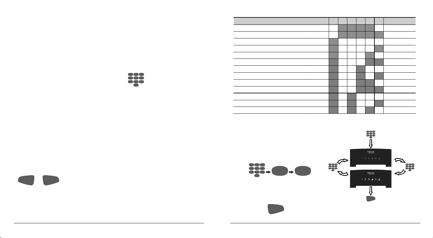
Adding a Proximity Card
To use proximity cards the system
has to be equipped with a proxim-
ity card reader.
Key sequence for adding a
proximity card:
CODE
PRG
6
0
(2 beeps)
USER
ID (00-16)
ENT
The card must be positioned near
the card reader.
Removing a Proximity Card
The key sequence for remov-
ing a proximity card:
CODE
PRG
6
1
(2 beeps)
USER
ID (00-16)
ENT
Real Time Clock Adjustment
Arbitrary units are used for real
time clock adjustment. One unit
corresponds to every 5 seconds
deflection per month. The value of
50 means there is no need for ad-
justment. The following method is
used to calculate the necessary
adjustment.
The necessary adjustment is cal-
culated by determining the num-
ber of days taken for the clock to
deflect by 1 minute. The adjust-
ment value is found by dividing the
number 360 by the number of days
found in the previous step. The
result obtained is added to the cur-
rent value in the case of a slow
clock or is subtracted from the cur-
rent value in case the clock runs
fast. The figure thus obtained is
entered into the system.
Example: Let us suppose the clock
is running slow by 1 minute in 85
days. The figure 4.2 is obtained
when 360 is divided by 85. The ad-
justment value of 54 is obtained
when the figure 4 is added to the
current set figure of 50.