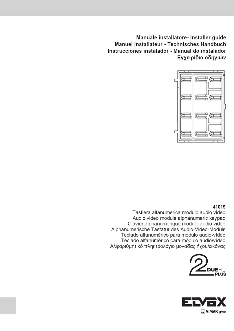
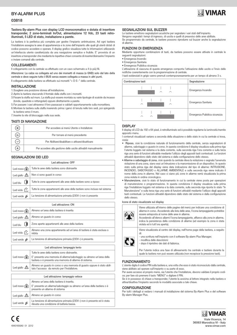
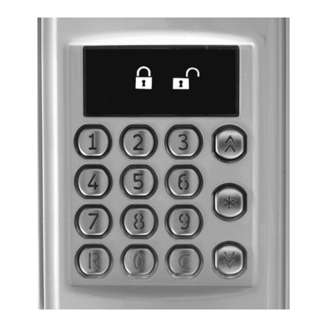
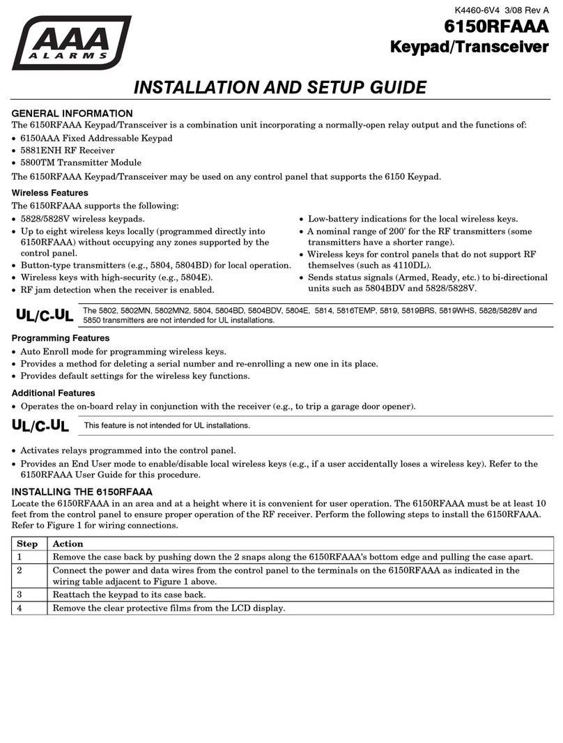
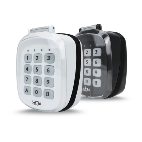
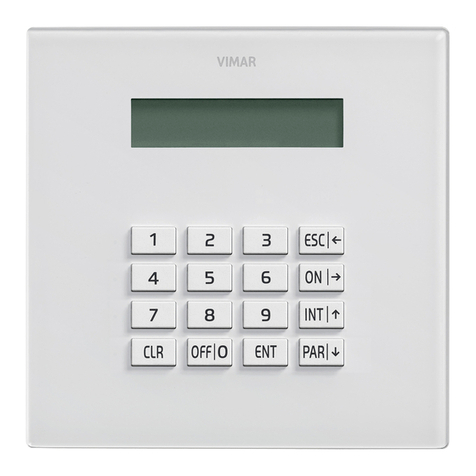
Vimar ELVOX 13F4 Assembly instructions

Art. 13F4, 13F7
Unità Due Fili audio con tastiera - Unità Due Fili colori con tastiera
keypad audio Due Fili unit / keypad colour Due Fili unit
Manuale installatore - Installer guide
3
2
1
1 2 3
4 5 6
7 8 9
0
ABC DEF
GHI JKL MNO
PQRS TUV WXYZ
+
R
3
2
1
123
456
7 8 9
0
ABC DEF
GHI JKL MNO
PQRS TUV WXYZ
+
R

2
Indice
Regole d’installazione e conformità normative....................................... 2
Descrizione............................................................................................. 3
Caratteristiche tecniche.......................................................................... 3
Unità elettronica...................................................................................... 4
Morsettiera.............................................................................................. 4
Collegamento di una TLC esterna tipo TVCC su unità elettronica audio.. 4
Accensione unità elettronica................................................................... 5
Codifica posti interni ............................................................................... 5
Assegnazione automatica identificativi ID .............................................. 6
Chiamata ................................................................................................ 6
Pulsanti tradizionali................................................................................. 7
Segnalazione Occupato-Attendere......................................................... 7
Apertura serratura da targa .................................................................... 7
Regolazione volumi ................................................................................ 7
Configurazione parametri ....................................................................... 8
Valore di default dei parametri................................................................ 8
Schemi di collegamento e varianti..........................................................35
Contents
Installation rules and regulatory compliance .......................................... 2
Description.............................................................................................. 19
Technical characteristics......................................................................... 19
Electronic unit .............................................................................................. 20
Terminal block.............................................................................................. 20
Connection of a CCTV type external camera to an audio electronic unit . 20
Switching on the electronic unit.............................................................. 21
Indoor unit ID codes .................................................................................... 21
Automatic ID assignment............................................................................ 22
Call ......................................................................................................... 22
Traditional buttons .................................................................................. 23
Engaged - Please Wait message ........................................................... 23
Door lock release from an entrance panel.............................................. 23
Volume adjustment................................................................................. 23
Parameter configuration ......................................................................... 24
Default value of parameters ................................................................... 24
Wiring diagrams and variants ................................................................ 35
IT EN
ITALIANO ENGLISH
REGOLE D’INSTALLAZIONE
L’installazione deve essere effettuata con l’osservanza delle disposizioni
regolanti l’installazione del materiale elettrico in vigore nel paese dove i
prodotti sono installati.
CONFORMITÀ NORMATIVA.
Direttiva EMC.
Norme EN 61000-6-1, EN 61000-6-3.
INFORMAZIONE AGLI UTENTI AI SENSI DELLA DIRETTIVA 2002/96
(RAEE)
Al ne di evitare danni all’ambiente e alla salute umana oltre che
di incorrere in sanzioni amministrative, l’apparecchiatura che riporta
questo simbolo dovrà essere smaltita separatamente dai riuti ur-
bani ovvero riconsegnata al distributore all’atto dell’acquisto di una
nuova. La raccolta dell’apparecchiatura contrassegnata con il simbolo del
bidone barrato dovrà avvenire in conformità alle istruzioni emanate dagli
enti territorialmente preposti allo smaltimento dei riuti. Per maggiori infor-
mazioni contattare il numero verde 800-862307.
INSTALLATION RULES
Installation should be carried out observing current installation regulations
for electrical systems in the country where the products are installed.
CONFORMITY
EMC directive
Standards EN 61000-6-1, EN 61000-6-3.
USER INFORMATION IN COMPLIANCE WITH EUROPEAN
DIRECTIVE 2002/96 (RAEE).
In order to avoid damage to the environment and human health as
well as any administrative sanctions, any appliance marked with this
symbol must be disposed of separately from municipal waste, that
is it must be reconsigned to the dealer upon purchase of a new
one. Appliances marked with the crossed out wheelie bin symbol must be
collected in accordance with the instructions issued by the local authorities
responsible for waste disposal.
The instruction manual is downloadable from the site www.
vimar.com
Il manuale istruzioni è scaricabile dal sito www.vimar.com

19
EN
Description
Electronic units 13F4 (audio) and 13F7 (video) can be used only in Due Fili Plus systems.
They are equipped with an alphanumeric keypad and the video version has a camera with a white LED lighting unit.
Electronic units 13F4 and 13F7 can be used as replacements in systems equipped with electronic units art. 12F4, 12F7. For entrance panels 89F4, 89F7 the
spare part is functional, not mechanical. Electronic units 13F4 and 13F7 can also be used in conjunction with traditional push-buttons. Up to two additional
button modules can be connected on single wire, art. 12TS, or one additional button module on 2-wire, art. 12TD.
Technical characteristics
- 1/4" CCD sensor (13F7)
- Minimum illumination 1.0 lux (13F7)
- Power via terminals B1, B2.
- Power via terminals Ext+, Ext- if the electronic unit needs to be powered via an additional power supply.
- Video signal output 16 dBm
- Current draw in standby 120 mA
- Current draw during communication 320 mA
- Current draw during communication and lock activation 470 mA
- Minimum voltage 24 V d.c. measured at terminals B1, B2
- Lens adjustable by hand, vertically and horizontally (13F7)
- Operating temperature: -10 °C / +55°C.
Electronic units 13F4 and 13F7 are suitable for both VERTICAL BUS and HORIZONTAL BUS installation. The default configuration is VERTICAL INSTAL-
LATION and features management of up to 200 users. The HORIZONTAL INSTALLATION configuration features electronic units that fully manage up to
1000 users each.
NOTE: The values indicated in square brackets refer to the "HORIZONTAL INSTALLATION” configuration.
1 2 3
4 5 6
7 8 9
0
ABC DEF
GHI JKL MNO
PQRS TUV WXYZ
+
R
3
2
1
Electronic unit
Wiring for connection
of additional button
modules
PRG buttonRESET
Wiring
for connection
terminal block
Figure 1
Figure 2
Terminal block
CN1) Connector for electronic unit.
CN2) Connector for programmer art. 950C or inter-
face art. 692I/U or art. 692I.
B2) Bus (cable riser).
B1) Bus (cable riser).
EXT+) External power supply (+ art. 6923).
EXT-) External power supply (- art. 6923).
VLED)
LED power supply for additional modules.
X) Video input (coaxial core) for external camera
(13F4).
M) Video input (coaxial sheath) for external ca-
mera (13F4).
PA) Input for door open sensor (with reference to
terminal M).
CA) Door open command (with reference to termi-
nal M).
M) Ground.
S+) Lock output 12Vdc (+) (see note below).
S-) Lock output 12Vdc (-) (see note below).
+12V) Output +12V (max 120 mA) with current limi-
ter.
-L) External camera pilot, open collector output
(13F4).
SR) Relay-operated lock pilot, open collector
output.
F2) Relay-operated F2 function pilot, open collec-
tor output.
F1) Relay-operated F1 function pilot, open collec-
tor output.
M) Ground.
B2
B1
EXT+
EXT-
VLED
M
PA
CA
M
S+
S-
+12V
-L
SR
F2
F1
M
X
B2
B1
EXT+
EXT-
VLED
M
PA
CA
M
S+
S-
+12V
-L
SR
F2
F1
M
X
CN2 CN1
CS2411 250105
Figure 3
Note: S+/S- outputs. The entrance panel supplies a
current peak of IT> 1A for 10 ms, followed by a holding
current of IM= 200 mA for the entire duration of the lock
command (see lock time).
Manual adjustment
horizontal and vertical

20
EN
Jumper position
SA
connected configuration as audio electronic unit (13F4)
disconnected the video configuration allows connection of a CCTV type exter-
nal camera to the audio electronic unit
Connection of a CCTV type external camera to an audio electronic unit
To connect an external CCTV camera to an audio electronic unit (13F4), the electronic unit must be configured as if it were intended for video entryphone
use. This type of configuration is accomplished by removing the SA jumper. To perform the operation, raise the alphanumeric keypad (see figure 4), remove
the SA jumper, then reinstate the alphanumeric keypad. Connect the camera as indicated in diagram SI367).
Figure 4
Figure 5
Figure 6
table 1

21
EN
Switching on the electronic unit
Each time the electronic unit is switched on, the display shows the ani-
mation of the Due Fili Plus logo. To skip it, press any key on the numeric
keypad. At the end a picture shows the main FW version, release date
and whether it is working as a Vertical or Horizontal Installation (V and H
respectively).
You can now press the and buttons simultaneously to enter the
factory conguration initialization procedure. Keep them pressed until con-
rmation on the display.
Factory initialization procedures
The number on the second line will be different each time. Key in the num-
ber displayed and then press the button. You can now:
Completely delete all the stored informa-
tion and then return the current congura-
tion to the factory default. This procedure
takes time.
Takes the current conguration to the fac-
tory default.
Checks the congruence of the internal
structures (Test) and corrects them if
there is any error (Fix).
Extracts the current conguration and
some of those after formatting. You need
special software for your PC.
Note: Except for 111, all these procedures are to be carried out only when
directed by Customer Service.
Note: The entire procedure for entering the 8 digits and selecting the func-
tion must be completed within 20 s of starting, with no timeout renewal.
After clearing the memory, the electronic unit restarts and reverts automat-
ically to at-rest status.
Other settings
Press button . The only current item is:
Enabling is essential in order to use the SW on PC SaveProg / EVCom.
Press 1 for YES and 0
+ for NO. To exit programming mode, press
R .
Default: Yes
Switching on the rst time
When the electronic unit is turned on for the rst time, the rst conguration
procedure starts automatically which consists in the prompt to specify some
basic parameters. The procedure is highlighted by this picture:
You can now run a subset of the congurations of the electronic unit, those
that most determine the operating characteristics or that are necessary for
other reasons.
PARAMETER PARAGRAPH
Language 1.0
Date and Time
format
4.10
Date and time 5.0
Installation 1.2
Electronic unit ID 1.1
The first switch-on procedure ends due to timeout (30 s) or by explicitly exit-
ing with . At the next restart it will no longer be automatically presented.
To invoke it again, press the RESET button and then keep the PRG button
pressed down until the first switch-on procedure is invoked.
Indoor unit ID codes
An unambiguous ID code can be attributed to each indoor unit. The encod-
ing is performed by the MASTER electronic unit that may be the electronic
unit with ID = 1 in the case of Vertical installation or Horizontal installa-
tion that on a Vertical bus has been remapped in the corresponding 69RS
as the vertical Master. During this procedure the MASTER electronic unit
communicates with the appliance being configured, and if this is a video
entryphone appliance, the display will also light up.
Configuration procedure:
-
Enter the ID code number assignment procedure, as indicated in the instructions
for the indoor unit to be coded.
- When the indoor unit enters ID assignment, the display of the electronic
unit acting as Master shows the following message (the figure shows the
case of a Vertical Installation):
- There are two areas on the first line. The area on the left indicates the
current code of the device being programmed and the one on the right
indicates the code to be assigned to the device. If the value of the left-
hand area is composed only of 0 digits, the device currently has no code
allocated.
- Enter the code to be allocated to the appliance. The code can be made
up of 3 digits (1...200) for Vertical Installation or 5 digits for Horizontal
Installation.
-
You can correct the digits entered by continuing to type in others.
- Press R to cancel programming, or press to confirm the value
entered.
- On confirming the value, the electronic unit will check that the code has
not already been allocated to another device.

22
EN
- There can be three cases:
ID already exists
Unique ID already assigned
Unique ID not assigned
The procedure applies both to the main ID and to a secondary one. In
the latter case, the ID to be entered is that of the main one (or master) to
which you want to link the indoor unit being assigned the ID. The range
of available values in this case is limited to 1..50 since the electronic unit
automatically calculates the secondary ID to be associated with it and finds
one that is available. If you enter an ID greater than 50:
- Repeat the procedure for all indoor units.
During programming, a timeout of 25 seconds is available in which to allo-
cate the code to a device, otherwise the electronic unit automatically exits
the procedure.
Note: The ID can only be assigned if the configuration in paragraph 1.8 is
set to Sequential.
Automatic ID assignment
1) Type in R + 6
MNO
2) Enter the current password (default 6
MNO 5
JKL 4
GHI 3
DEF 2
ABC 1 ), confirm
with .
3) Indicate the ID number from which to start the allocation process.
4) Run the ID assignment procedure for the indoor unit within 5 minutes (for
the procedure please refer to the product's instructions).
5) The electronic unit communicates with the indoor unit being programmed
and assigns the ID chosen in point 3).
6) The electronic unit automatically makes a call to the indoor unit that has
just been encoded. You can answer or let it end.
7) Repeat the procedure from step 4) onwards, to complete the automatic
ID number allocation for other devices. The new ID will be increased by 1.
Note: the timeout setting is approximately 5 minutes, renewable at the end
of each operation.
Note: the programming will lock up if there is an indoor unit in the system
already having an associated ID number located internally of the allocation
window. For example, if ID = 5 is typed into the electronic unit and there are
indoor units that have already been allocated an ID number lower than 5,
there will be no problem running the automatic procedure. Should there be
an indoor unit in the system that has previously been allocated the number
ID = 9, the programming function will allocate 5, 6, 7, 8, and then lock up,
due to the fact that 9 already exists and therefore cannot be allocated.
To continue with automatic allocation, the user must correct the sequence
manually, in this instance at step 3) of the procedure, by entering the num-
ber ID = 10.
Note: The maximum number of secondary IDs for each primary ID that can
be configured with the procedure described here is 3. IMPORTANT: First
encode the secondary IDs, then the relevant master.
Note: In the event that a secondary ID number is already in use (for ex-
ample the first secondary number of ID = 1 happens to be 51 and 51 has
already been allocated, the unit will be allocated the first secondary ID
available.
Call
On alphanumeric electronic units, there are 4 ways of dialling a user and
sending a call:
- Numeric dial.
- Alphanumeric dial.
- Direct dial.
- Traditional buttons.
Numeric dialling
Dial the call code of the desired extension using buttons 0
+ to 9
WXYZ . Press
R to cancel the operation or to call. When dialling, if 0
+ is active
for selection of the “Lock code" (paragraph 1.9), do not utilize 0
+ as the
first button. If the code called is associated with a name in the contacts list,
the first associated name (a) will be displayed while the call is being made.
Note: The concierge switchboards are associated with the numbering from
201 (40001) onwards. For ease of use you can select them directly with
buttons and (paragraphs 2.0 and 2.1) or the traditional buttons,
configuring them as described in section 4.2.
Alphanumeric selection (if there is at least one name in the
contacts list)
Press button .Enter all or the first few letters of the name to be found. To
enter characters/symbols, use buttons 0
+ to 9
WXYZ . Each button has more
than one character/symbol associated with it (see table 3).
Button
Symbol
(IT-EN-FR-DE-ES-PT)
Symbol
(EL)
1 <space>1@.,:;?!()<> Space 1@.,:;?!()<>
2
ABC ABC2abcÁÀĂÃÅÄÆÇČĆáàăãåäæçč ΑΒΓ2ΆABCabc
3
DEF DEF3defÉÈÊĚĘďéèêě ΔΕΖ3ΈDEFdef
4
GHI GHI4ghiÍÌíì ΗΘΙ4ΉΊΪGHIghi
5
JKL JKL5jklŁ ΚΛΜ5JKLjkl
6
MNO MNO6mnoÑñÓÒŎÕÖØóòŏõöø ΝΞΟ6ΌMNOmno
7
PQRS PQRS7pqrsŘŠřšßŚ ΠΡΣ7PQRSpqrs
8
TUV TUV8tuvÚÙÜŮúùüů ΤΥΦ8ΎΫTUVtuv
9
WXYZ WXYZ9wxyzÝŽŹŻýžΧΨΩ9ΏWXYZwxyz
0
+ 0_$&*#+-=/%”’ 0_$&*#+-=/%“‘
Table 3
To find the desired symbol, press the button repeatedly before the end of
the 2 s timeout, which is renewed with each press of the button.
If the symbol entered previously was an upper case character, even if the
button is changed, the function will restart with upper case. If the symbol
was lower case, the function will restart with lower case. If the symbol was
a digit, the function will restart with a digit. To enter a character /symbol
located on a different button from the one previously pressed, it is not nec-
essary to wait for the end of the timeout.
Use the and buttons to start the name search.
If the name entered forms part of the name being searched for, the elec-
tronic unit will display the first name that meets the search criteria; use the
and buttons to scroll back and forth through the list.
Having found the name, press the button to send a call. Press the R
button to cancel the operation.
Direct dialling
Pressing one of the two buttons, a call can be made directly to
two different numbers. This is possible only if the two buttons have been
encoded as described in paragraphs 2.0 and 2.1.
Traditional buttons
Up to two 12TS button modules or one 12TD button module can be con-
nected for calls directed to a specific user. The associated buttons are sub-
ject to the configurations described in paragraphs 1.5, 1.6, 1.7, 4.2 and 4.3.
Note: In whatever way a call has been started, you can cancel it by pres-
23
EN
sing the R button, or make a new one directly by keying in the new code
and confirming with . You can also press one of the additional buttons
but in this case the entrance panel must have completed the chime cycles,
paragraph 4.1.
Engaged - Please Wait message
When the display shows:
the electronic unit is disabled for making calls, because another call is in
progress from an electronic unit located on the same bus. If during the mes-
sage you try to make a call, the electronic unit will emit a long warning tone.
Mute chimes function (on indoor unit)
If a call is made to an indoor unit with the “chimes muted” function active,
the electronic unit will generate a beep through the loudspeaker and display
the message:
indicating that a call cannot currently be made to the user.
Self-start
If the self-start function is activated from an indoor unit, the electronic unit
will display the message:
If a call is made in this situation, the effect will be to cancel the self-start
procedure.
Door lock release from an entrance panel
The lock of an electronic unit can be operated if at least one of the possible
1000 codes, from 1 to 8 digits, is known beforehand. Before entering the
code digits, the preset access code must be entered, as described under
heading 1.4, default R + 1 .
In the meantime, the display shows the active buttons:
Enter all code digits:
Pressing , the system checks whether or not the code already exists. If
it does, the local lock is activated. In the event of error, there is no warning.
If a mistake is made when entering data, press R and start again.
Opening F1 from entrance panel
Proceed as in the previous case, but the access code is R + 2
ABC and is
not configurable.
Opening F2 from entrance panel
Proceed as in the previous case, but the access code is R
+
3
DEF and is
not configurable
.
Note: The procedures described above are possible only with the entrance
panel at rest, i.e. no calls, self-starting, or configurations in progress. Some
codes can be employed only during certain time bands. See paragraph 5.1.
Volume adjustment
YOU can adjust the external, internal, balance and chimes volume, during
a conversation and with no need to access the internal settings of the en-
trance panel. The adjustments can be made only after enabling the func-
tion, as described below.
- Press buttons R +5
JKL .
- When the following messages are displayed in alternation :
enter the parameter programming password; the default password is 6
MNO
5
JKL 4
GHI 3
DEF 2
ABC 1 .
- Every time a button is pressed there will be a short “beep”, an asterisk
“*” appears on the display, and there are a further 25 seconds (timeout)
in which to press the next button. If the timeout is allowed to elapse with-
out pressing any button, the electronic unit will exit programming mode.
After entering the password, press the button to activate the func-
tion. If the password is correct, the electronic unit will briefly display the
message:
When the next call is made, the following messages appear cyclically on
the display:
When you answer, the following messages appear cyclically on the display:
If an indoor unit self-starts to this selfsame entrance panel you get to adjust
the external volume directly. Use the buttons to raise or lower the
chosen level. To save the chosen level, press . When the configuration
is saved the display will show:
Pressing the button cycles through the adjustments of all the other
levels.
At the end of the conversation, which is terminated by replacing the handset
or when the conversation timeout elapses or if the R button of the elec-
tronic unit is pressed, the volume control function is cancelled.

24
EN
Parameter default settings
Parameter Default Parameter Default
1.0 Message language Italian 3.5 Door Open send time Disabled
1.1 Entrance panel ID 13.6 External volume 3
1.2 Installation Vertical Bus 3.7 Internal volume 3
1.3 Initial ID (+) 13.8 Balancing 8
1.4 Final ID (+) 1000 3.9 Chime Volume 0
1.5 First button ID 13.10 Lock interlock No
1.6 Button remapping HW 3.11 Enabling Direct enabled, Common disabled
1.7 Single buttons Yes 4.0 Entrance panel chime Yes
1.8 No. coding digits Sequential coding 4.1 No. chime cycles 2
1.9 Lock code R+1 4.2 Switchboard pb Not assigned
2.0 Preferential code Not assigned 4.3 Button Audio call Not assigned
2.1 Preferential code Not assigned 4.4 Com. lock Not assigned
2.2 Lock codes Not assigned 4.5 F1 common Not assigned
2.3 F1 codes Not assigned 4.6 F2 common Not assigned
2.4 F2 codes Not assigned 4.7 Disable SB search (*) Yes
2.5 No. Dev. (-) Not assigned 4.8 Disable self-start (*) No
2.6 Search all contacts No 4.9 Seq. Self-start (*) Not assigned
2.7 Contacts Name Not assigned 4.10 Date and Time format 01/01/2014 00:00
2.8 Program Password 654321 5.0 Clock 01/01/13 00:00
2.9 Answer time 30 s 5.1 Enable timed codes No
3.0 Conversation time 120s 5.2 First Time Call 0
3.1 Self-start time 10 s 5.3 Last Time Call 0
3.2 Lock time 1 s 5.4 Band Not assigned
3.3 Function 1 Time 1 s 5.5 Device (°)
3.4 Function 2 Time 1 s 5.6 Button (°)
Notes: (*) configurable only with MASTER or horizontal electronic unit, (°) only in the vertical configuration, (+) only in the horizontal configuration,
(-) only if No. Coding Digits is not Sequential.
table 2
Parameter configuration
Changes are made connecting one electronic unit at a time.
In systems with several electronic units, one unit must be identified as a MASTER and the other units as SLAVE units, regardless of model or type (alpha-
numeric, buttons, landing). All entrance panels are supplied with the electronic unit set as MASTER (ID = 1).
Procedure for accessing parameter configuration mode
You have to start with the electronic unit in a state of rest: there must be no calls in progress, no self-starting or anything similar.
Press buttons R + 4
GHI . Release the buttons.
Key in the password, by default 6
MNO 5
JKL 4
GHI 3
DEF 2
ABC 1 . Every time a button is pressed there will be a short “beep”, an asterisk “*” appears on the display,
and there are a further 25 s in which to press the next button. If you let the timeout elapse, the electronic unit will return to rest.
After entering the password, press the button. If the password is correct, the electronic unit goes into parameter configuration mode. If the password is
wrong, the electronic unit exits the procedure and reverts to at-rest status. The operation must be repeated.
Note: The information that appears in square brackets refers to the case of active Horizontal Installation, paragraph 1.2.

25
EN
The following sections describe the possible configurations of the electronic units using the keypad and display. For
all of them, to confirm the change in configuration, the first line of the display shows:
In the event of parameter error, the display shows a situation similar to this:
You can go to the next setting by pressing the button, to the previous one with . Exceptions are those settings
that regard the indoor units (for example, the contacts list) or that refer to a number of sub-configurations (for exam-
ple, time slots). For these, with you go to the indoor unit or to the next sub-configuration, to reach the end of the
previous setting. With the R button you skip straight to the previous setting. Settings that behave in this way are
highlighted by the R symbol next to the title.
The button is used to cancel the change in progress or to return the electronic unit to rest if there are no pending
changes.
1.0 - Message language
Indicates the language used for displaying messages both during normal use (user messages) and for the config-
uration of the electronic unit (technical messages). To change the set language, press the number on the keypad
corresponding to the required language as indicated in the table or use the arrow keys.
BUTTON 0
+ 1 2
ABC 3
DEF 4
GHI 5
JKL 6
MNO
LANGUAGE Italian English French German Spanish Portuguese Greek
Press to confirm the change. The confirmation message will be displayed in the new language.
Default: Italian
1.1 - Entrance panel ID
Identifies the electronic unit with a code between 1 and 15 [1 and 36]. If the value is 1, the electronic unit is set as
MASTER, if the value is between 2 and 15 [2 and 36], the electronic unit is set as SLAVE.
Enter the identification code using buttons 0
+ to 9
WXYZ . Press to confirm the change. Confirming the change, the
electronic unit checks the availability of the code. If there is another electronic unit connected with the same code in
the system, the display will show a message such as this:
and it is necessary to enter another code.
Pressing 0 will “disable” the electronic unit temporarily.
Default: 1
Note: Do not use ID 15 in the case of a downstream Vertical installation of a 69RS.
1.2 - Installation
You choose the installation mode for the electronic unit: 0
+ for Vertical Installation or 1 for Horizontal Installa-
tion.
Default: Vertical
Note: Exiting the configuration and returning the electronic unit to rest forces sorting the contacts list.
Note: When going from Horizontal to Vertical installation congruence with other existing settings is checked. If there
are any of them that in the Vertical configuration are no longer valid, the electronic unit will show this with a message
regardless of the language and with a numerical code:
To confirm the move from Horizontal to Vertical, that in this case involves automatic deletion of incompatible settings,
depress the button. With you cancel the procedure, leaving the electronic unit in Horizontal mode and without
losing the settings.
1.3 - Initial ID
This item appears only if the Horizontal configuration has been selected in step 1.2. It is necessary to indicate the first
1.0
Message language
1.1
Entrance panel ID
1.2
Installation
1.3
Initial ID

26
EN
ID in the range of the (video) door entry units for which some configurations can be made in the electronic unit. They
are: remapping in the event of non-sequential numbering, contacts list, enabling use of the lock / F1 / F2, self-starting.
Default: 1
1.4 - Final ID
This is the same thing as paragraph 1.3 except that it refers to the last ID in the same range.
Default: 1000
Note: The breadth of the resulting window must be less than or equal to 1000. If it is not, the electronic unit will au-
tomatically correct the error, taking it to a maximum value of 1000, and it will warn the user to check the other end in
order to be sure of the automatically corrected value and if necessary modify it to better suit your needs.
1.5 - First button ID
Configuration relating to additional button modules 12TS and 12TD (if installed). Using the numeric keys, indicate
which ID must correspond to the first button (the one at top right) of the first additional module installed and confirm
with . The following buttons will correspond to consecutive increasing IDs.
Default: 1
1.6 - Button remapping R
Configuration relating to additional button modules 12TS and 12TD (if installed). You can change the associated code
individually for each of the 8 possible buttons that the electronic unit manages. The number shown at the top right of
the display is independent of the setting described in paragraph 1.5.
Choose the number of the button to be remapped, with the arrows or by typing in a number from 1 to 8 and confirming
with , or directly by pressing one of the buttons of the additional modules installed. To change the associated
number, depress and type in the value of the remapping, confirming with .
Default: 0, no remapping
Note: If the settings of paragraphs 1.5 and 1.6 are simultaneously present, Button Remapping takes priority.
1.7 - Single buttons
If you use modules Art. 12TS, activate mode 1 = Single buttons. Using Art. 12TD, activate 0
+ = Double buttons.
Default: Single Buttons.
1.8 - Number of coding digits
Sets the type of encoding for calls to indoor units.
- Sequential coding, 3 [5] digits, indoor units are numbered with codes between 1 and 200 [6400]. In this configu-
ration, a 0 in front of the other digits is irrelevant.
- 4 digit coding, in this configuration, codes can be from 1 to 4 digits. Valid only for Vertical installation.
- 8 digit coding, in this configuration, codes can be from 1 to 8 digits.
Button 1 Sequential coding 3 [5] digits Indoor unit numbering from 1 to 200 [6400]
Button 2
ABC
4-digit coding (only for Vertical installa-
tion) Indoor unit numbering from 1 to 9999
Button 3
DEF 8-digit coding Indoor unit numbering from 1 to 99999999
Note: The 4-digit and 8-digit coding parameters activate DEVICE NUMBERING, paragraph 2.5. It is mandatory
to fill in DEVICE NUMBERING at least for those indoor units that you want to be enabled for calling. An ID without
remapping cannot be called by this electronic unit, unless you have configured either a traditional button or one of
and .
Note: Where 4 or 8 digit numbering is selected, 0 digits on the left are significant. For example, 14, 014 and 0014
are three distinct numbers.
Default: Sequential
1.9 - Lock code
Sets the buttons needed to enter the lock release procedure directly with the keypad of the electronic unit. Linked with
this there is the LOCK KEY programming of paragraph 2.2.
BUTTON PROCEDURE START CODE NOTE
1 0
+
This type of selection is not recommended when the call codes
may require 0 as the first selected digit.
1.5
First button ID
1.6
Remap. Button 1
1.7
Single Buttons
1.8
No. Coding Digits
1.4
Final ID
1.9
Lock code

27
EN
2.1
Preferential code
2.0
Preferential code
2
ABC R + 1
3
DEF
Default: R + 1
2.0 - Preferential code
Associates the button with a code for calling an indoor unit or the concierge switchboard, with no need to know the
name or number, without needing to key it in and without confirming it with . The call code to enter is independent
of the value set in the NUMBER OF ENCODING DIGITS parameter described in paragraph 1.8. The physical ID must
always be entered, not the value that may have been remapped.
Enter the call code, complete with all digits, using buttons 0
+ to 9
WXYZ . Use the R button to cancel the last digit
entered. Press to confirm the change. Numbers 201 to 204 [40001...40008] are the janitor switchboard numbers.
To cancel programming enter 0
+ as the ID.
Default: blank
2.1 - Preferential code
As for the previous point but referred to .
2.2 - Lock passwords R
UP to 1000 different codes can be recorded, comprising 8 digits maximum, to release the lock directly from the keypad
of the entrance panel. Use the buttons to select one of the 1000 passwords. Alternatively, enter the number
of the password and press to select. Having located the required password, press the button to change
the value. Enter the code to record (up to 8 digits). Use the R button to cancel the last digit entered. Press to
confirm the change.
Default: blank
Note: There is no relationship between the number of passwords and the maximum breadth of the ID range in the case
of Horizontal installation. There are always 1000 passwords, also in the case of Vertical installation.
The activation time is set with LOCK TIME, paragraph 3.2. The function is not subject to enabling as described in
paragraph 3.9.
2.3 - F1 passwords R
As in paragraph 2.2, but referred to the output F1 and the times of paragraph 3.3.
2.4 - F2 passwords R
As in paragraph 2.2, but referred to the output F2 and the times of paragraph 3.4.
2.5 - Device numbering R
The procedure is only active if the numbering is not sequential, paragraph 1.8. A call code of up to 8 digits must be
associated with each indoor unit. The mapping function associates the physical code from 1 to 200 [or the index in a
range of 1000 codes] of each indoor unit with the call code that needs to be keyed in.
For Vertical Installation the first number shown is always 1. In the case of Horizontal Installation it has the same value
as the Initial ID, paragraph 1.3. For example, if 3000 applies:
Use the buttons or the numeric keypad + to select one of the codes. Having located the required code,
press the button to change the value. Enter the code to be recorded, press the button to confirm the change.
To cancel the last digit entered, press R .
If the call code has already been allocated, the electronic unit will display a message similar to this one:
To cancel an existing code, select the code in question, press to enable changes, enter one 0
+ and press .
To cancel all the associations, next to any code press 0
+ , and when this message is displayed:
2.3
F1 codes
2.4
F2 codes
2.2
Lock code
2.5
Device number

28
EN
press 1 and to confirm.
After confirming the operation, wait for completion of the cancellation process.
Default: no association.
Note: You can use the codes from 201 to 204 [from INITIAL ID + 1000 to INITIAL ID + 1007, from 1001 to 1008 by
default], for the concierge switchboards.
A code without remapping cannot be called by this electronic unit, unless you have configured either a traditional
button or one of and .
2.6 - Search the entire contacts list
With this item, the electronic unit can be configured to scroll through the entire contacts list by entering a blank name
as the search string. Normally, at least the first letter of the name to be searched should be entered With the FLAG
selected, press then or to see respectively the first and last names in the contacts list, whatever the initial
letter.
The and buttons can then be used to scroll through the entire contacts list. To enable the setting, press 1
and confirm with . To deactivate the function, press 0
+ and .
In the case of Horizontal Installation other codes that change the function are possible. They are:
BUTTON SEARCH THE ENTIRE CONTACTS LIST...
2
ABC
NO, and with the keypad calls are allowed only if there is a corresponding name in the
contacts list.
3
DEF YES, and with the keypad calls are allowed only if there is a corresponding name in the
contacts list.
4
GHI NO, and with the keypad calls are allowed only if the ID is within the start-end range.
5
JKL
YES, and with the keypad calls are allowed only if the ID is within the start-end range.
Default: No
2.7 - Device names R
The electronic units have an electronic contacts list for 200 [1000] users. Each user can be assigned two names (a
and b) of 16 characters each.
Use the buttons or key in the number + to select one of the 200 [1000] users.
Each user is matched with two names (aand b), to be selected with buttons . Having located the required
line, press the button to change the value. Once change mode is activated, the blinking cursor will show where
to enter the character.
To enter characters / symbols, use buttons 0
+ to 9
WXYZ . Each button has more than one character/symbol associated
with it (see table 3). To find the desired symbol, press the button repeatedly before the end of the 2 second timeout,
which is renewed with each press of the button. If the symbol entered previously was an upper case character, even
if the button is changed, the function will restart with upper case. If the symbol was lower case, the function will restart
with lower case. If the symbol was a digit, the function will restart with a digit. To enter a character / symbol located on
a different button from the one previously pressed, it is not necessary to wait for the end of the timeout.
When entering symbols, the and buttons can be used to scroll along the line, and the R button to delete
the character to the left of the cursor. Press to confirm the change. After confirmation, the electronic unit will
check whether or not the name entered is already used in another position. If it is already used the display will show
a message similar to this:
and it will be necessary to enter another name. When searching for uniqueness, uppercase and lowercase letters are
distinct. Whereas when searching for a call there is no distinction.
Note: You can use the codes from 201 to 204 [from INITIAL ID + 1000 to INITIAL ID + 1007, from 1001 to 1008 by
default], for the concierge switchboards.
Default: blank.
2.8 - Programming password
Sets the password for access to configuration from keypad. Enter the new password using buttons 0
+ to 9
WXYZ . Press
2.6
Search all Contacts
2.7
Contacts name
2.8
Password

29
EN
2.9
Answer time
3.0
Conversation time
3.1
Self-start time
3.2
Lock time
3.3
Function 1 Time
to confirm the change.
Default: 654321
2.9 - Answer time
This is the interval of time, expressed in seconds, that the electronic unit waits from the end of the call signal until there
is an answer from the indoor unit. If there is no response within the "answer time", the electronic unit ends the call. If
the indoor unit answers before the set interval elapses, the electronic starts to count the conversation time.
Enter the new time with buttons 0
+ to 9
WXYZ . Press to confirm the change.
Default: 30 s, minimum value 1 s, maximum value 255 s.
3.0 - Call time
This is the interval of time, expressed in seconds, that the electronic unit monitors from the moment that a call is
answered by the indoor unit. Once the interval has elapsed, the electronic unit ends the call. Enter the new time with
buttons 0
+ to 9
WXYZ (in steps of 10 s). Press to confirm the change.
Default: 120 s, minimum value 10 s, maximum value 2550 s.
3.1 - Self-start time
This is the time, in seconds, of the duration of the self-start function. Once the interval has elapsed, the electronic unit
disconnects the indoor unit. Enter the new time with buttons 0
+ to 9
WXYZ . Press to confirm the change.
Default: 10 s, minimum value 1 s, maximum value 255 s.
3.2 - Lock time
Activation time of the lock connected between terminals S+ / S- and +12V / SR.
Enter the new time with buttons 0
+ to 9
WXYZ . Press to confirm the change.
Default = 1 s, minimum value 0 s corresponding to lock always off, maximum value 255 s.
3.3 - Function 1 time
Activation time of the device connected between terminals +12V / F1. Enter the new time with buttons 0
+ to 9
WXYZ . For
the minimum value of 0.5 seconds. enter 0
+ . Press to confirm the change.
Default = 1 s.
3.4 - Function 2 time
Activation time of the device connected between terminals +12V / F2. Enter the new time with buttons 0
+ to 9
WXYZ . For
the minimum value of 0.5 seconds. enter 0
+ . Press to confirm the change.
Default = 1 s.
3.5 - D.O. (door open) send time
Normally an entrance panel sends over the bus a notification of the D.O. (Door Open) input status only when it
changes. The Master entrance panel sends the global status (at least one door is open or all the doors are closed)
only when it changes. In some situations it is desirable for this to be done periodically. Using buttons 0
+ to 9
WXYZ
enter the send time in minutes. 0
+ to disable. Press to confirm the change.
Default = disabled, 1' minimum, 90' maximum
3.6 - External volume
THIS is the voice volume of the speaker attached to the electronic unit, which can be adjusted through 8 steps. Press
to enable changes to the volume setting. Press the buttons to increase or reduce the volume. Press
to confirm the change.
Default = 3
3.7 - Internal volume
THIS is the volume of the speaker fitted to the electronic unit, which can be adjusted through 8 steps. Press to
enable changes to the volume setting. Press the and buttons to increase or reduce the volume. Press
to confirm the change.
Default = 3
3.4
Function 2 Time
3.6
External volume
3.5
D.O. Send Time
3.7
Internal volume

30
EN
3.8 - Balance
THIS adjusts the audio compensation on 16 levels between the input channel and output channel (in order to eliminate
any possible Larsen effect). Press to enable changes to the volume setting. Press the and buttons to
increase or reduce the volume. Press to confirm the change.
Default = 8
3.9 - Chimes volume
THIS is the volume of the chimes attached to the electronic unit, which can be adjusted through 4 steps. Press
to enable changes to the volume setting. Press the and buttons to increase or reduce the volume. Press
to confirm the change.
Default = 0
3.10 - Lock interlock
Activation of the lock interlock enables operation of the lock only when the electronic unit is in call, conversation or
self-start status.
Press 1 to activate the interlock; press 0
+ to deactivate the interlock. Press to confirm the change.
Default = No
3.11 - Enabling R
ONE or more electronic units can be configured in such a way as to inhibit or enable lock release, F1 and F2 control
signals received from indoor units. Letter Dis used to indicate the disabled status of Direct control signals transmitted
to the electronic unit. Letter C is used to indicate the enabled status of indirect control signals, i.e. activated at the
same time as others, for example the lock release of a different electronic unit (see lock / F1 / F2 Common, paragraphs
4.4, 4.5, 4.6).
Use buttons and or the numeric keypad to select the identifier of the indoor unit to which to apply the enabling
and confirm with . Once found, enter changes with . Using buttons 1 to 6
MNO enable the controls, see Table 8.
BUTTON ACTION
1 Direct lock
2
ABC F1 direct
3
DEF F2 direct
4
GHI Common Lock
5
JKL F1 common
6
MNO F2 common
Table 8
It is possible to set enabling and disabling simultaneously for all the indoor units, for one or more outputs. The proce-
dure is described below, but you should use the configuration software for a PC.
For the first digit to choose the indoor unit press 0
+ . The display will show the confirmation request.
The numeric keys now have the following meaning:
BUTTON DISPLAY DIRECT ACTION COMMON ACTION
0
+
Nothing changes Nothing changes
1 Sets to default the DIRECT
enabling of lock, F1, F2, ie
enables all
Sets to default the COMMON
enabling of lock, F1, F2, ie di-
sables all
2
ABC Sets to default the DIRECT
enabling of the lock, ie enables
them
Sets to default the COMMON
enabling of the lock, ie disables
them
3
DEF Sets to default the DIRECT
enabling of F1, ie enables them
Sets to default the COMMON
enabling of F1, ie disables them
3.8
Balancing
3.9
Chime volume
3.10
Lock interlock
3.11
Enable-inhibit settings

31
EN
4.1
No. Chime cycles
4.0
Entrance panel chime
BUTTON DISPLAY DIRECT ACTION COMMON ACTION
4
GHI Sets to default the DIRECT
enabling of F2, ie enables them
Sets to default the COMMON
enabling of F2, ie disables them
5
JKL
Removes from default the DI-
RECT enabling of lock, F1, F2, ie
disables all
Removes from default the COM-
MON enabling of lock, F1, F2, ie
enables all
6
MNO Removes from default the
DIRECT enabling of lock, ie
disables them
Removes from default the COM-
MON enabling of lock, ie enables
them
7
PQRS Removes from default the DI-
RECT enabling of F1, ie disables
them
Removes from default the COM-
MON enabling of F1, ie enables
them
8
TUV Removes from default the DI-
RECT enabling of F2, ie disables
them
Removes from default the COM-
MON enabling of F2, ie enables
them
9
WXYZ
Switches to Common. The rst
letter of the second line becomes
C.
Switches to Direct. The rst letter
of the second line becomes D.
Default = direct commands enabled, indirect commands disabled
4.0 - Entrance panel chime repetition
Enables repetition of the chime in the speaker of the electronic unit. Press 1 to activate the chime; press 0
+ to
deactivate it. Press to confirm the change.
Default = Yes
4.1 - Number of chime cycles
Following the transmission of a call, the electronic unit (see paragraph 4.0) and the indoor units emit a certain number
of chime cycles that can be selected with this setting. A chime cycle lasts for a total of 3 s (1 s chime, 2 s pause). Enter
the number of cycles with buttons 0
+ to 9
WXYZ . Press the button to confirm.
Default = 2
4.2 - Consumer unit button R
For each of the 4 [8] configurable consumer units, you can choose a traditional button that makes a direct call to it.
Use the and buttons to choose the number of the consumer unit. Then key in the number of the button or 0
+
to cancel the program. Press the button to confirm.
Default: not configured.
4.3 - Audio call button R
This parameter enables configuring 8 IDs for receiving an audio call even if the signal is sent from a video electronic
unit. Use the buttons to choose the location to be programmed, then buttons 0
+ to 9
WXYZ to select the ID.
Press the button to confirm.
Default: not configured.
4.4 - Common locks R
This parameter allows indirect lock release, coinciding with the lock release of another electronic unit, controlled by
an indoor unit or a consumer unit, not by the local CA / M button. You can at the most associate indirect release with
8 different electronic units. Use the and buttons to choose the location to be programmed, then buttons 0
+
to 9
WXYZ in order to enter a number between 1 and 15 [1 and 8248], that is the ID of an electronic unit, for controlling
the lock of which also the electronic unit being configured must enable its own. To confirm, press . To cancel the
allocation, enter 0
+ as the ID.
Entering numbers between 21 and 36 [10001 and 16000], then the programmed element will not be an electronic
unit, but an operator or relay module. Number 21 identifies the 1st relay of the 1st operator. Unlike the lock, F1 or F2,
operators are not governed by any kind of disabling, as described under heading 3.11. For display purposes, entrance
panels have a letter "P" prefix, and operators a letter "A". The large numbers are essential in order to associate the
entrance panels or the relays of the vertical risers as they are seen in the horizontal bus.
Default: no association
4.2
Consumer unit button
4.3
Button Audio call
4.4
Com. lock

32
EN
4.5 - F1 common R
As for the lock, but for the output F1.
4.6 - F2 common R
As for the lock, but for the output F2.
4.7 - Disable slave panel search
This parameter is only present if the entrance panel is the Master or is configured for Horizontal Installation. It can be
used to disable the search for Slave electronic units via the Master electronic unit, on start-up or after pressing the
RESET button. Press 1 to deactivate the search, and 0
+ to activate the search. Press to confirm the change.
Default = Yes
4.8 - Self-start disabling
This parameter is only present if the entrance panel is the Master or is configured for Horizontal Installation. It inhibits
self-starting from all the system's indoor units. Press 1 to deactivate self-start, and 0
+ to activate self-start. Press
to confirm the change.
Default = No
4.9 - Self-start sequence R
This parameter is only present if the entrance panel is the Master or is configured for Horizontal Installation. With
this parameter, the cyclical start-up of a sequence of electronic units can be associated with the self-start button of
each indoor unit. Use the and buttons or the numerical keypad to select one of the 200 [1000] physical codes
(device ID) corresponding to an indoor unit.
Note: You can use the codes from 201 to 204 [from INITIAL ID + 1000 to INITIAL ID + 1007, from 1001 to 1008 by
default], for the concierge switchboards, but with the current FW the self-start function is not performed.
Having located the required code, press the button to change the value. The R button deletes the last electronic
unit in the sequence. To enter the numbers of the electronic units, proceed as indicated in the following table:
Vertical installation Horizontal
installation Number / Letter First
Button
Second
Button
Third
Button
1 H1 1 1
2 H2 2 2
ABC
3 H3 3 3
DEF
4 H4 4 4
GHI
5 H5 5 5
JKL
6 H6 6 6
MNO
7 H7 7 7
PQRS
8 H8 8 8
TUV
9 H9 9 9
WXYZ
10 H10 A 0
+ 0
+
11 H11 B0
+ 1
12 H12 C 0
+ 2
ABC
13 H13 D 0
+ 3
DEF
14 H14 E 0
+ 4
GHI
15 H15 F 0
+ 5
JKL
H16 G 0
+ 6
MNO
V1 H 0
+ 7
PQRS
V2 I 0
+ 8
TUV
V3 J 0
+ 9
WXYZ
V4 K 0
+ 0
+
V5 L 0
+ 1
V6 M 0
+ 2
ABC
4.6
F2 common
4.7
Disable SB search
4.5
F1 common
4.8
Disable S.start
4.9
Seq. Self-start

33
EN
V7 N 0
+ 3
DEF
V8 O 0
+ 4
GHI
V9 P 0
+ 5
JKL
V10 Q 0
+ 6
MNO
V11 R0
+ 7
PQRS
V12 S 0
+ 8
TUV
V13 T 0
+ 9
WXYZ
V14 U 0
+ 0
+
Note: In the case of Horizontal installation, the prefix Hindicates a Horizontal electronic unit, while Vindicates one of
the vertical electronic units of the riser where there is the indoor unit. V15 does not exist, its function is performed by the
69RS. Cyclic self-starting is possible only on the first 16 horizontal electronic units. For the others, direct self-starting
is possible, after suitably programming the 69RS.
After the first 0
+ , or second or button, a symbol will appear indicating that another number key is expected.
A “clipboard” function can be used to help with duplication of the codes. When no symbol is shown as described above,
press to record the sequence shown on the display. Select another device, access changes mode and press
to replace the existing sequence with the sequence recorded in the clipboard. Press to confirm the change.
Note: Each horizontal electronic unit can function as a Master (as regards self-starting) for the indoor units whose ID is
within the Initial ID - Final ID range (paragraph 1.3 and 1.4). It is enough for 69RS to have the Master entrance panel
of the riser remapped onto the current entrance panel.
Default: no sequence, so only the Master entrance panel (Vertical Installation) or the current one (Horizontal
Installation) is considered.
4.10 - DATE / TIME format
While awaiting selection, the electronic unit shows, among other information, the current date and time. The formats
in which they are shown are configurable. If desired, you can also delete one or both of them. Enter changes mode
with , select the desired format with or , confirm with . The time format is reached with starting
from the date format.
Default: display date in the format day month / numeric month / 4-digit year, hour and minutes in 24H format
separated by ':', 01/01/2013 00:00:00.
5.0 - Clock
The clock must be set correctly for the service described in paragraphs 5.1 to 5.4 to be able to be correctly performed.
The date and time are retained for at least 2 days even with the electronic unit switched off. When the clock is first
powered up, or when the electronic unit remains switched off for longer than 2 days, the date is automatically set to 1
January 2013 and the time to 00:00. To adjust the date and time, press . The modifiable field is indicated by a solid
rectangle to the right. To change the data for the day, enter numbers 0
+ .. 9
WXYZ with the keypad and to move on to
another field, use the button to move right and to move left. Confirm with . If there is an error, for example
if the day is set any higher than 31, changes are rejected and the rectangle moves to the position of the error. There
is no need to enter the day of the week, as this will be calculated automatically from the date.
5.1 - Enable timed codes
This configuration enables the timed password function described under headings 5.2, 5.3 and 5.4. To enable press
1 . To disable press 0
+ .
Default: No
5.2 - First timed code
This configuration specifies the first code to be used for the Timed Codes function. Using buttons from 0
+ to 9
WXYZ
enter its number from 1 to 1000 or 0
+ to delete it. If the first code is higher than the second, or if one is programmed
and the other is not, a warning to check the other code is displayed. The valid codes are those in which the number
ranges from the first to the last as specified, excluding the limits.
Default: not programmed
5.3 - Last timed code
Like the code described above, but referring to the last valid code.
Default: not programmed
5.0
Clock
4.10
Date / Time format
5.1
Enabled time codes
5.2
First Call Time
5.3
Last call Time

34
EN
5.4 - Code validity time slots
The clock of the electronic units 13F4 and 13F7 allows enabling a certain number of Lock codes, F1 codes, F2 codes
described in paragraphs 2.2, 2.3 and 2.4 only at certain times of the day.
Two time bands are envisaged for the 24-hour period, each with a resolution of 30 minutes. The start and end of the
interval can be specified in increments of 30 minutes:
00:00, 00:30, 01:00, 01:30, … 22:30, 23:00, 23:30.
For additional flexibility, the two time bands can be programmed separately for weekdays (Monday to Friday) and for
weekends or holidays, or in any event for most days not regarded as full working days (typically Saturday and Sunday).
Note: There is no management of holidays such as Christmas, Easter Monday, etc.
The codes for all three types of function (lock, F1 and F2) have common start and end numbers, although the con-
tents of the three tables can obviously be programmed differently. The codes not included in the selected set remain
permanently active. Only the selected codes are subject to time limits. The service can be disabled temporarily by
means of programming procedure 5.1. In this case the specified codes are never active, while the others remain
permanently active.
The end must be higher than the start, otherwise the configuration will not be valid. For example, Start = 16:00 and
End = 16:00 would not be valid, and neither would Start = 16:00 and End = 10:30.
To change the time, press . A double arrow appears to the right of the minutes, indicating that buttons and
can be used to adjust the time
by increments of 30 minutes. Alternatively use buttons 0
+ .. 9
WXYZ to set the time only. If need be, buttons and
can be used to set the minutes.
Default: not programmed
5.5 - Change indoor unit configurations
This function is only available for Vertical Installation.
For each indoor unit installed in the system, it is possible to configure operating options grouped in four segments:
Flags, Programmable buttons, Call groups and Landing call. Certain indoor units have a fifth segment, namely audio/
video levels. To carry out this procedure, the devices being programmed (indoor units) must be connected to the sys-
tem and be already identified with a code. The electronic unit searches for the first device (indoor unit), identified by
ID 1, and analyses the type. Us buttons to select one of the 200 devices. If you want to access a particular
ID directly, enter the number and press the button to select it.
Having located the required device, press the button to access its change configuration mode. The configuration
resides entirely in the device, i.e. the electronic unit shows only what is present, it does not store anything inside her-
self. The configuration options vary according to the type of device. With changes mode activated, use the ,
and R buttons to navigate the parameters, and the button to confirm any changes made. For the area of the
Flags, 0
+ means No and 1 means Yes.
5.6 - Button 6120
This function is only available for Vertical Installation.
This section permits configuring 6120 button modules. An ID code must already have been assigned to Module 6120,
see product instructions.
The procedure is similar to that for the Programmable buttons of the indoor units.
Note: Given the complexity of the configurations, and the lack of support for the Horizontal Installation, it is recom-
mended to use the PC software.
5.5
Device
5.6
Button 6120
5.4
Time Slot

35
ENIT
Schema di collegamento unità elettronica audio o video
Wiring diagram for audio or video electronic unit
B1
12B2
EXT+
EXT-
M
PA
X
VLED
B1
B2
S+
S-
F2
F1
SR
-L
+12V
M
M
CA
EXT+
EXT-
M
PA
X
VLED
B1
B2
S+
S-
F2
F1
SR
-L
+12V
M
M
CA
12
RETE
MAINS
VLED
-L
M
F2
F1
SR
CA
S-
+12V
S+
M
M
PA
X
B2
EXT+
EXT-
B1B1
EXT-
EXT+
B2
X
PA
M
M
S+
+12V
S-
CA
SR
F1
F2
M
-L
VLEDVLED
-L
M
F2
F1
SR
CA
S-
+12V
S+
M
M
PA
X
B2
EXT+
EXT-
B1
B1
EXT-
EXT+
B2
X
PA
M
M
S+
+12V
S-
CA
SR
F1
F2
M
-L
VLED
12
B1
12B2
RETE
MAINS
Montante
Cable riser
F
x
D
F
P
L
x
x
xx
x
L L L
P P P
C C C
Schema di collegamento di più unità elettroniche audio
Wiring diagram for multiple audio electronic units
C - Unità elettronica audio o video
F - Alimentatore di sistema
L - Serratura elettrica 12 Vdc
P - Comando apriporta
X - Cavo twistato
C - Unità elettroniche audio
F - Alimentatore di sistema
L - Serratura elettrica 12 Vdc
P - Comando apriporta
X - Cavo twistato
Montante
Cable riser
C - Audio or video electronic unit
F - System power supply unit
L - Electric lock 12 V DC
P - Door release control
X - Twisted pair cable
C - Audio electronic units
F - System power supply unit
L - Electric lock 12 V DC
P - Door release control
X - Twisted pair cable
Schemi di collegamento - Wiring diagrams

36
EN IT
Schema di collegamento di più targhe video o più targhe video e targhe audio
Wiring diagram for multiple video entrance panels or multiple video and audio entrance panels
Schema di collegamento di unità elettronica audio singola con TLC tipo TVCC esterna
Wiring diagram for single audio electronic unit with CCTV type external camera
CA
M
M
+12V
-L
SR
F1
F2
S-
S+
B2
B1
VLED
X
PA
M
EXT-
EXT+
B22
1B1
CA
M
M
+12V
-L
SR
F1
F2
S-
S+
B2
B1
VLED
X
PA
M
EXT-
EXT+
MV-+T
-L-+U
12
RETE
MAINS RETE
MAINS
C
M1
SF
x
x
L
P
Montante
Cable riser
Montante
Cable riser C - Unità elettroniche video
F - Alimentatore di sistema
L - Serratura elettrica 12 Vdc
P - Comando apriporta
X - Cavo twistato
G - Alimentatore supplementare alimentazione unità elettronica
C - Unità elettronica audio
F - Alimentatore di sistema
L - Serratura elettrica 12 Vdc
M1 -Telecamera esterna tipo TVCC (12 Vdc)
P - Comando apriporta
S - Alimentatore supplementare Art. 6982
X - Cavo twistato
* Congurata come unità elettronica video (ponticello SA non inserito).
Congured as video electronic unit (SA jumper not inserted).
Montante
Cable riser
*
C - Video electronic units
F - System power supply unit
L - Electric lock 12 V DC
P - Door release control
X - Twisted pair cable
G - Additional power supply for electronic unit
C - Audio electronic unit
F - System power supply unit
L - Electric lock 12 V DC
M1 -External CCTV type camera (12 V DC)
P - Door release control
S - Additional power supply unit art. 6982
X - Twisted pair cable
Other manuals for ELVOX 13F4
1
This manual suits for next models
1
Table of contents
Other Vimar Keypad manuals

Vimar
Vimar Elvox 8016 Assembly instructions

Vimar
Vimar By-alarm 01705 User manual

Vimar
Vimar ELVOX 41019 Assembly instructions

Vimar
Vimar ELVOX 41019 User guide

Vimar
Vimar BY-ALARM PLUS 03818 User manual

Vimar
Vimar ELVOX 41020 User guide

Vimar
Vimar ELVOX PIXEL UP 40405 Owner's manual

Vimar
Vimar ELVOX 41020 Assembly instructions