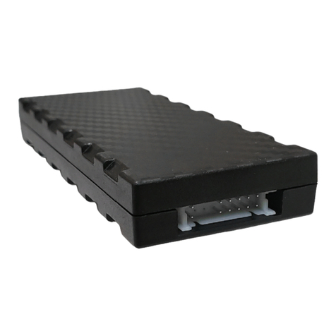
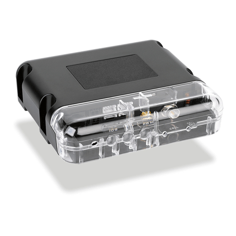
TELETRAC NAVMAN Qtanium 400 User manual

Qtanium 400
INSTALLATION MANUAL

Qtanium 400 | Installation Manual
ii
Contents
1OVERVIEW ................................................................................................................. 5
2HARDWARE ............................................................................................................... 6
2.1 OTHER COMPONENTS REQUIRED .......................................................................................6
2.2 POWER CABLE OPTIONS ..................................................................................................6
2.3 I/O CABLES FOR (OPTIONAL)ADDITIONAL CONNECTIONS.......................................................6
3MOUNTING LOCATIONS............................................................................................. 7
3.1 ANTENNA MOUNTAIN LOCATION.......................................................................................7
3.2 QTANIUM 400 MOUNTING LOCATION ...............................................................................7
4INSTALLATION............................................................................................................ 9
4.1 BEFORE STARTING ..........................................................................................................9
4.2 START THE INSTALLATION .................................................................................................9
4.3 MOUNT THE QTANIUM 400...........................................................................................10
4.4 CABLING.....................................................................................................................10
4.5 CONNECT THE POWER CABLE ..........................................................................................11
4.6 CONNECT THE POWER CABLE/BUILT-IN IPS UNIT ...............................................................12
4.7 CONNECT THE EXTERNAL BATTERY BACKUP OR SOLAR PANEL (OPTIONAL) ...............................13
4.8 CONNECT ANY OPTIONAL EQUIPMENT..............................................................................14
4.8.1 Digital Inputs.......................................................................................................14
4.8.2 Digital Outputs....................................................................................................16
4.8.3 Multi I/O-1 & I/O-2..............................................................................................17
4.8.4 Connect the 7-Way Cable (Optional) ..................................................................18
4.8.5 Teletrac Navman Temperature Probes...............................................................18
4.8.6 Connect an 18-Way Cable (Optional) .................................................................18
4.8.7 Connection to a Quake Satellite Modem ............................................................19
4.9 POWER UP THE QTANIUM 400.......................................................................................19
4.10 TEST THE INSTALLATION WITH ONLINEAVL2/DIRECTOR ....................................................20
4.11 APPLY THE TAMPER-EVIDENT SEAL...................................................................................21
5TROUBLESHOOTING................................................................................................. 22
5.1 RECOMMENDED PROCEDURE ..........................................................................................22
5.2 PERFORM A COLD RESET ................................................................................................22
6DIMENSIONS............................................................................................................ 24
7SPECIFICATIONS....................................................................................................... 25

Qtanium 400 | Installation Manual
iii

Qtanium 400 | Installation Manual
iv
Disclaimer
It is the Owner’s sole responsibility to install and use the Qtanium 400 (the Product) in a manner that will
not cause accidents, personal injury or property damage. For the purpose of this notice, “Owner”, “you”
and “your” means the party (including any person authorized by that party to use and/or install the
Product) that has either: (a) purchased the Product; (b) leased or rented the Product from Teletrac
Navman or its related companies; or (c) subscribes to Teletrac Navman’s subscription service and such
subscription incorporates the use of the Qtanium 400 product.
The Owner of this Product is solely responsible for observing safe driving practices.
The choice, location and installation of all components of the Product is critical. If installation is not
correct, the Product may not perform at its designed potential or specifications. If in doubt, consult your
Teletrac Navman dealer.
The Qtanium 400 is sealed in the factory and tested for watertight integrity. Unauthorized opening of the
unit will compromise the IP-67 rating, will invalidate the warranty, and may result in failure due to ingress
of water or other substances.
TO THE MAXIMUM EXTENT PERMITTED BY LAW, ALL REPRESENTATIONS AND WARRANTIES (EXCEPT ANY
WHICH MAY NOT LAWFULLY BE EXCLUDED) ARE, EXPRESSLY EXCLUDED, INCLUDING WITHOUT PREJUDICE
TO THE, GENERALITY OF THE FOREGOING, THE IMPLIED WARRANTIES OR MERCHANTABILITY AND
FITNESS FOR A PARTICULAR PURPOSE. TO THE MAXIMUM EXTENT PERMITTED BY LAW TELETRAC
NAVMAN DISCLAIMS ALL LIABILITY ARISING OUT OF OR IN CONNECTION WITH THE PRODUCT (INCLUDING
ANY USE OF THIS PRODUCT IN A WAY THAT MAY CAUSE ACCIDENTS, DAMAGE OR VIOLATE THE LAW).
As Teletrac Navman is continuously improving this Product, Teletrac Navman may make changes to the
Product at any time which may not be reflected in this document. Please contact your nearest Teletrac
Navman office if you require any further assistance.
TELETRAC NAVMAN DISCLAIMS ALL LIABILITY FOR ANY USE OF THIS PRODUCT IN A WAY THAT MAY CAUSE
ACCIDENTS, DAMAGE OR VIOLATE THE LAW.
EMC Compliance
This device complies with Part 15 of the FCC Rules. Operation is subject to the following two conditions:
(1) This device may not cause harmful interference, and (2) this device must accept any interference
received, including interference that may cause undesired operation.
Copyright
© 2016 Teletrac Navman Holdings L. P. Teletrac Navman is a registered trademark of Teletrac Navman
Holdings L. P. All rights reserved. All other trademarks and registrations are the property of their
respective owners.

Qtanium 400 | Installation Manual
5
1 Overview
The Qtanium 400 is a ruggedized Automatic Vehicle Location (AVL) unit that is installed into
heavy duty vehicles (assets) such as those used for construction. It communicates with a
server and allows information about the asset to be stored and monitored.
The Qtanium 400 is a combined GPS (Global Positioning System) and communications
product that contains:
a GPS receiver to provide accurate location data
a cellular antenna that enables data to be transferred between the asset and the
server
an on-board microprocessor for data processing and storage, and external
communications
6 Digital I/O and 2 Multi I/O
an internal battery that is charged from a permanent external power supply, such as
the asset’s battery, through the power cable. When fully charged, the internal
battery has the capacity to report one event per day for up to three months. It takes
approximately 25 hours to charge the internal battery following a full discharge,
although this time can vary depending on the external temperature
In addition, the Qtanium 400 can optionally be connected to:
an external lead-acid backup battery, to avoid full discharge of the internal battery
a solar panel for trickle charging the internal battery
a maximum of 6 Teletrac Navman temperature probes
an MDT, M-Nav, or other serial device
other auxiliary devices
Note This installation manual is written for professional vehicle technicians.

Qtanium 400 | Installation Manual
6
2 Hardware
The box contains:
1 Qtanium 400
4 mounting magnets
Qtanium 400 Quick Install Card
2.1 Other Components Required
You also need the following components before starting the installation:
a power cable (see the following section for options)
a cellular antenna
a GPS antenna
WIFI antenna (with WIFI option)
You may also need any or all of the following components, depending on your installation:
I/O cable(s) to connect digital or other types of auxiliary devices and sensors
2.2 Power Cable Options
There are two choices of power cable:
3 m (9.8 ft.) heavy duty 16-gauge wire, plastic armored sheath with choke
6 m (19.6 ft.) heavy duty 16-gauge wire, plastic armored sheath with choke
2.3 I/O Cables for (Optional) Additional Connections
There are three choices of ruggedized cable for optional additional connections:
7-Way cable (SAP Code 10001345) for digital sensors or devices I/O
18-Way cable (SAP Code 10001346) for auxiliary or serial devices I/O
18-Way satellite modem cable (SAP Code 10001384) for connection to a Quake
Satellite Modem and/or auxiliary or serial devices
Note If desired, you can mount the Qtanium 400 using high-powered magnets such as
M5 or equivalent (not supplied).
Note The power cable and two antennas are the minimal requirement for tracking
only.

Qtanium 400 | Installation Manual
7
3 Mounting Locations
3.1 Antenna Mountain Location
Ensure that the antenna location provides a good view of the sky for optimum GPS
performance. You must use a Teletrac Navman-approved antenna. This must be IP-67 rated
if the antenna will be mounted in an exposed location with little or no protection from the
weather.
3.2 Qtanium 400 Mounting Location
The installation is considered to be permanent because the firmware can be updated
without removing the Qtanium 400 from the asset.
When selecting a mounting location, consider the length of the cables and proximity to all
connection points. Mount the Qtanium 400 and associated cabling in a location that does
not contain moving parts or obstruct serviceable areas.
Although the Qtanium 400 has an IP-67 rating, Teletrac Navman recommends that you
mount it in a location that will provide maximum protection from dust, water, and vibration.
The Qtanium 400 is rated up to 70°C but Teletrac Navman recommends that you choose a
mounting location that minimises exposure to extreme temperatures. Also be aware that,
Important The antenna must be located at least 20 cm (8”) from any person to meet
FCC radio frequency exposure requirements.
Note Use of an antenna that is not approved by Teletrac Navman, or an antenna that
is installed contrary to recommendations, may result in poor GPS or cellular
performance and may invalidate your warranty.
Important The Qtanium 400 contains an accelerometer that detects movement. It is
critical that the Qtanium 400 is mounted securely on a rigid surface where it cannot
move independently of the asset and / or vibrate off its mounting location. The final
orientation of the Qtanium 400 after installation is not important.

Qtanium 400 | Installation Manual
8
due to the battery chemistry, battery operation will be impaired at high temperatures; in
particular, it will not charge when the temperature reaches, or exceeds, 45°C. need to check
ratings.

Qtanium 400 | Installation Manual
9
4 Installation
This section describes the process of installing the Qtanium 400 on a vehicle.
4.1 Before Starting
1. Check that you have all the components needed to complete your installation.
2. Identify the best mounting location for the Qtanium 400 and the antennas. Make
sure that the proposed location for the Qtanium 400 provides sufficient space for
easy access to its connectors.
3. Test the proposed antenna locations, if possible, to check whether they provide the
best performance.
4. Decide on the most suitable mounting method for your chosen location (screws /
nuts and bolts / magnets).
5. On the asset, identify where you will connect:
To asset’s chassis/after ground isolator switch (brown wire)
To asset’s battery negative/before ground isolator switch (black wire)
To asset’s +12/24V uninterrupted supply (red wire)
To asset’s ignition/run signal (pink wire).
6. Check that the power cable is long enough to reach between the power source and
your chosen location for the Qtanium 400.
7. Check that the antenna cables are long enough to reach between your chosen
locations for the Qtanium 400 and the antennas.
8. Check that any other cables are long enough to connect the Qtanium 400 to any
other optional devices or sensors.
4.2 Start the Installation
1. Disable the asset (turn the battery switch OFF or disconnect a battery post).
2. Mount the antenna and run the antenna cable but do NOT cut it. Where possible,
choose a location where the antenna has a clear view of the sky and is protected
from physical damage. (GPS performance will be impaired if the antenna cannot get
a clear view of the sky).
3. Run the Qtanium 400 power cable.

Qtanium 400 | Installation Manual
10
4.3 Mount the Qtanium 400
After you have run the Qtanium 400 power cable, mount the Qtanium 400 securely on - or
in - the asset using 4 self-tapping screws or 4 nuts and bolts.
Place the screws or bolts through the two slots along both sides of the Qtanium 400.
If you are mounting the Qtanium with magnets, we recommend magnetic mounts sized for
M5 screws.
The Qtanium 400 must be attached securely at all four corners.
4.4 Cabling
We recommend that you leave a service loop in each cable, near to the Qtanium 400, with
enough slack to allow working room and strain relief.
Ensure that all cabling is:
tidy and secure so that it is not a hazard to the users of the asset
protected from heat sources and from chaffing on sharp edges
connected to manufacturer’s approved points and run along factory harnesses
located where it will not be pinched or damaged.
Important Ensure that any holes drilled for the installation will not weaken the
structure of the asset or compromise the safety of the asset or its occupants. If in
doubt, consult the manufacturer. If mounting holes are required, use grommets to
ensure that the asset remains waterproof.
Important Individually insulate any unused bare wires and cover all unused ports
with end-caps. Use ONLY weatherproof sealable heatshrink ring terminals and butt
connectors for all electrical connections. Failure to use these may void the warranty
and damage the Qtanium 400 and / or other equipment. Do NOT use nylon or vinyl
connectors.

Qtanium 400 | Installation Manual
11
4.5 Connect the Power Cable
To connect the Qtanium 400:
1. Unscrew and retain the cover over the power port, then plug in the power cable and
tighten the locking screw.
2. If you want to connect any auxiliary devices to the Qtanium 400, see section Error!
Reference source not found.. Otherwise, remove the cover over the 18-Way cable
connector and replace it with the one removed from the power connector, to create
a waterproof and dustproof seal.
3. Wire the other end of the power cable as follows:
WIRE COLOR
FUNCTION
DESCRIPTION
Red
+12/24V
Power supply/positive
Assets without a battery disconnect switch: Connect
to the positive post on the asset’s battery or another
suitable permanent power source. This connection
must be fused (3 Amp slow blow).
Assets with a positive side isolation/disconnect
switch: Connect on the battery side (hot side) of the
manual or electronic positively isolated disconnect
switch OR to the positive post on the asset’s battery.
Do NOT connect on the cold side of the disconnect
switch. This connection must be fused (3 Amp slow
blow).
Assets with a negative side isolation/disconnect
switch: See section Error! Reference source not
found..
Pink
Engine Run
Positive input when ignition is ON or engine is running.
Connecting to the ignition signal will not allow accurate
assessment of actual engine hours. If this is required,
Important If the asset has a negative side isolation/disconnect switch. Refer to section
4.6 for advice.
Note Always remove the cover supplied on the 18-Way cable connector as this
includes a link to put the Qtanium 400 into shipping mode.

Qtanium 400 | Installation Manual
12
connect to a signal that indicates engine running. This
connection must be fused (3 Amp inline) in a
weatherproof fuse holder.
Black
Ground
Power supply/negative
Connect to the negative post on the asset’s battery or
asset’s chassis.
Assets with a negative side isolation/disconnect
switch: See section 4.6.
Brown
Ground
Chassis/negative
Connect to the negative post of the asset’s battery or
the asset’s chassis.
Assets with a negative side isolation/disconnect
switch: See section 4.6.
Orange
External
Backup
Battery
(Optional) If required, connect to an external battery
as a backup to the main power supply. Alternatively,
connect to a solar panel to trickle-charge the internal
battery. See section 4.7 for details.
If this wire is not used, apply adequate insulation to
the wire.
4.6 Connect the Power Cable/Built-in IPS Unit
The new Qtanium has IPS built in and simplifies installations on assets that have a manual or
electronic battery disconnect switch on the ground cable.
The built in IPS unit is suitable for 12 and 24 V vehicles and provides a regulated, isolated
power source for the Qtanium 400. It includes over-voltage and short-circuit protection with
automatic recovery.
To connect the Qtanium 400 to assets with a negative side isolation/disconnect switch:
1. Unscrew and retain the blanking cover over the power port, then plug in the power
cable and tighten the locking screw.
Warning Failure to install the IPS according to these instructions may create an
alternate path from the asset’s chassis to the negative battery post (through the casing
and wiring of the Qtanium 400). This may result in large currents flowing through the
Qtanium wiring, resulting in equipment damage and possible fire.

Qtanium 400 | Installation Manual
13
2. If you want to connect any auxiliary devices to the Qtanium 400, see section 4.8.
Otherwise, remove the blanking cover over the 18-Way cable connector and replace
it with the one removed from the power connector, to create a waterproof and
dustproof seal.
3. On assets with a negative side isolation/disconnect switch, wire the power cable as
follows:
WIRE COLOR
FUNCTION
DESCRIPTION
Red
+12/24V
Connect to the positive post on the asset’s battery or
another suitable permanent power source. This
connection must be fused (3 Amp slow blow).
Pink
Engine Run
Positive input when ignition is ON or engine is running.
Connecting to the ignition signal will not allow accurate
assessment of actual engine hours. If this is required,
connect to a signal that indicates engine running. This
connection must be fused (3 Amp inline) in a
weatherproof fuse holder.
Black
Ground
Battery Negative (before ground isolator switch).
Brown
Ground
Asset chassis connection (after ground isolator switch).
Orange
External
Backup
Battery
(Optional) If required, connect an external battery as a
backup to the main power supply. Alternatively,
connect to a solar panel to trickle-charge the internal
battery. See section 4.7 for details.
If this wire is not used, apply adequate insulation to
the wire.
4.7 Connect the External Battery Backup or Solar Panel (Optional)
You can optionally connect the Qtanium 400 to an external lead-acid battery to allow for
battery backup operation. This allows the Qtanium 400 to run off the main power supply
and trickle-charge the lead-acid backup battery. Then, if the main power supply fails or is
disconnected, the Qtanium 400 will continue to run by drawing power from the backup
battery.
Note Always remove the oversized shipping plug supplied on the 18-Way cable
connector as this includes a link to put the Qtanium 400 into shipping mode. Attach the
blanking cover over the 18-Way cable connector when not in use.

Qtanium 400 | Installation Manual
14
To connect the Qtanium 400 to an external lead-acid battery:
1. Connect the orange wire of the power cable directly to the positive terminal of the
backup battery.
2. Ground the negative terminal of the backup battery at the same location used by
the black wire in the Qtanium 400 power cable.
Alternatively, you can connect the orange wire to a solar panel to allow trickle-charging of
the internal battery. Contact Teletrac Navman for further information regarding this option.
4.8 Connect Any Optional Equipment
The Qtanium 400 can be connected to a variety of Teletrac Navman peripherals such as an
MDT, M-Nav, or third party equipment through Serial, 1-Wire, Digital, or Analogue Inputs.
The Qtanium 400 can generate events (e.g. door opening) or monitor the asset (e.g. oil
pressure) based on I/O from Digital Inputs.
This connectivity is provided through the 7-Way and 18-Way connectors on the front panel
of the Qtanium 400.
4.8.1 Digital Inputs
The Digital Inputs must be connected to circuits that are either ON or OFF. The Digital Inputs
can be configured to detect either positive switching (Active High, Biased Low) or negative
switching (Active Low, Biased High). Polarity is not important but must be noted for the
correct configuration to be sent to the Qtanium 400.
Positive Switching Configuration
A positive switching input requires a sourcing input of +12/24 V. When configured for
positive switching, the input state is considered ON when it becomes high.
The voltage thresholds that trigger the change in the input state are as follows:
STATE
VOLTAGE
High
>5.0 V
Low
<1.0 V / Disconnected
Note The backup battery must operate at the same voltage as the main power supply
used by the Qtanium 400. For example, if the Qtanium 400 is powered from 24 V DC,
the backup battery must be 24 V DC too.

Qtanium 400 | Installation Manual
15

Qtanium 400 | Installation Manual
16
Negative Switching Configuration
A negative switching input requires a Ground switching input; that is, an open circuit to
Earth (or vice versa).
When configured as for negative switching, the input state is considered ON when it
becomes low.
The voltage thresholds that trigger the change in input state are as follows:
STATE
VOLTAGE
High
>0.5 V
Low
<0.2 V / Disconnected
4.8.2 Digital Outputs
The Digital Output(s) have an open collector transistor-type arrangement and are controlled
by the dispatcher through the OnlineAVL2/DIRECTOR software.
A Digital Output pulls low with a maximum current of 250 mA when activated. It has an
over-current tripped protection. If tripped, the output must be changed to OFF, or have a
power cycle to reset the current trip.
Digital Output(s) are commonly used to prevent unauthorized starting of the asset and/or to
activate accessories.

Qtanium 400 | Installation Manual
17
4.8.3 Multi I/O-1 & I/O-2
Each Multi I/O can be configured in one of three different operating modes:
Digital Input
Digital Output
Analogue Input
Digital Input
When configured for Digital Input, Multi I/O-1 and Multi I/O-2 can only operate as Active
High Inputs, with the Active High functionality and wiring as described in section Error!
Reference source not found..
Digital Outputs
When configured for Digital Output, Multi I/O-1 and Multi I/O-2 operate as for the DO-1 and
DO-2 lines.
Analogue Inputs
When configured for Analogue Input, Multi I/O-1 and Multi I/O-2 connect to devices that
have a variable voltage output.
The input voltage range is 0–33 V DC. If the input voltage range exceeds 33 V DC, the input
must be scaled. To scale the voltage correctly, calculate the maximum sensor voltage to
scale to the max 33 V DC at the Analogue Input.
Note When the satellite modem is enabled, Multi I/O-2 cannot be used.

Qtanium 400 | Installation Manual
18
4.8.4 Connect the 7-Way Cable (Optional)
To connect the 7-Way cable to the Qtanium 400, unscrew the blanking cover over the 7-
Way cable connector then push the 7-Way cable onto the connector and hand-tighten the
locking screw.
Connect the 7-Way cable wires to any external signals as follows:
PIN
WIRE COLOR
FUNCTION
DESCRIPTION
1
Black
Ground
2
Yellow
MI/0-1
Multi I/O
3
Purple
DI-4
Digital Input 4
4
Blue
DI-3
Digital Input 3
5
Blue/White
DI-2
Digital Input 2
6
Green/White
DI-1
Digital Input 1
7
Grey
DO-2
Digital Output 2
4.8.5 Teletrac Navman Temperature Probes
The Qtanium 400 can support up to six Teletrac Navman digital temperature probes and can
also use some of the Multi I/O and Digital Inputs for temperature event monitoring.
4.8.6 Connect an 18-Way Cable (Optional)
1. To connect an 18-Way cable to the Qtanium 400, remove and retain the shipping
plug from the 18-Way connector. (The shipping plug prevents the Qtanium 400 from
powering ON during shipping. The plug is also used to COLD RESET the Qtanium 400
in the unlikely event of any problems; see section 5.2.)
2. Push the 18-Way cable onto the connector and hand-tighten the locking screw.
3. Connect the 18-Way cable wires to peripheral devices as follows:
PIN
WIRE COLOR
FUNCTION
DESCRIPTION
1
Black
Ground
Ground output
2
White
~+3.8 V
Ref
Power Supply/3.8V
3
Green
MI-02
Multi I/O
4
Light Blue
TxD-2
RS232 Serial Port
2/transmit
5
Light Blue/Black
RxD-2
RS232 Serial Port 2/receive
6
Orange
~+3.8 V
Ref
Power Supply/3.8V
7
Orange/White
1WD
Temperature Probe Data
Front View
Front View

Qtanium 400 | Installation Manual
19
8
Black
Ground
Ground Output
9
Brown/White
RxD-3
RS232 Serial Port 3/receive
10
Brown
TxD-3
RS232 Serial port
3/transmit
11
Yellow
DO-1
Digital Output 1
12
Red
~+12/24 V
Power supply output
13
Orange/Black
RTS-1
RS232 SP1/Request to
Send
14
Black/White
TxD-1
RS232 Serial Port
1/transmit
15
Red/White
RxD-1
RS232 Serial Port 1/receive
16
Pink
CTS-1
RS232 SP1/Clear to Send
17
N/A
Shipping
Internal Battery disconnect
18
N/A
Shipping
Internal Battery disconnect
4.8.7 Connection to a Quake Satellite Modem
If you want to connect the Qtanium 400 to a Quake Satellite Modem, you need the 18-Way
satellite modem cable.
Satellite Modem for Qube 4 and Qtanium 400 Installation Manual.
4.9 Power Up the Qtanium 400
When the installation is complete, perform the following steps in the order listed to bring
the Qtanium 400 online promptly.
1. Screw the cellular (TNC) antenna cable to the connector on the Qtanium 400.
2. Screw the GPS (SMA) antenna cable to the connector on the Qtanium 400.
3. Insert fuses into fuse holders.
4. Remove and RETAIN the shipping plug from the 18-Way connector. If you have not
installed an 18-way cable, attach a blanking plug. (The shipping plug is used to Cold
Reset the Qtanium 400 in the unlikely event of any problems –see section 5.2.)
5. Test the installation as described in the following section.
Note When using the satellite modem, be aware that some of the I/O will be reserved
for satellite use.

Qtanium 400 | Installation Manual
20
4.10 Test the Installation with OnlineAVL2/DIRECTOR
To check that the Qtanium 400 is installed correctly and can communicate with the
OnlineAVL2/DIRECTOR software:
1. Position the asset outside in a location that provides a good view of the sky and
good cellular reception.
2. Verify/record the asset’s name/number and calibrate engine hours in
OnlineAVL2/DIRECTOR (Device Properties).
3. If the asset has a negatively isolated disconnect switch, toggle this to check that it
does not affect the Qtanium 400’s power supply. If it creates Power Up and Power
Removed events in OnlineAVL2/DIRECTOR, check the black wire (see section 4.6).
4. Start the engine and allow up to five minutes to initiate OnlineAVL2/DIRECTOR
reporting.
5. Check that OnlineAVL2/DIRECTOR shows an Ignition On event. If not, check the pink
wire (see section 4.5).
6. While the engine is running, check the Satellites column in OnlineAVL2/DIRECTOR.
Five (or more) satellites are required. If the number of satellites is low, move the
asset and/or select a different location to mount the GPS antenna.
7. Verify/configure sensor activity in OnlineAVL2/DIRECTOR for any sensors connected
to Digital Inputs, if applicable.
Note We recommend using a mouldable plastic sealant such as COAX-SEAL® around
the antenna connectors if the asset is used in a very dusty or very wet environment.
Although the Qtanium 400 has an IP-67 rating, it is considered best practice to protect
the RF connectors in this manner.
Table of contents
Other TELETRAC NAVMAN GPS manuals
TELETRAC NAVMAN
TELETRAC NAVMAN Qtanium 100 User manual
TELETRAC NAVMAN
TELETRAC NAVMAN Qtanium200 User manual

TELETRAC NAVMAN
TELETRAC NAVMAN Qtanium 100 User manual

TELETRAC NAVMAN
TELETRAC NAVMAN iFace User manual
TELETRAC NAVMAN
TELETRAC NAVMAN TM470 Series Installation guide
TELETRAC NAVMAN
TELETRAC NAVMAN iFace User manual
TELETRAC NAVMAN
TELETRAC NAVMAN Qube300 Installation guide
