TELETRAC NAVMAN Qube300 Installation guide

Installation Training and Troubleshooting
Qube300
M-Nav800
7/26/2016

2
Fleet Tracking & Management
Recommended Installation Practices
Recommended Tools and Supplies
Qube300 Hardware
Identifying Correct Wires
“Poke & Wrap”Solder-less Connections
Chassis Ground Connection
Mounting the Antenna
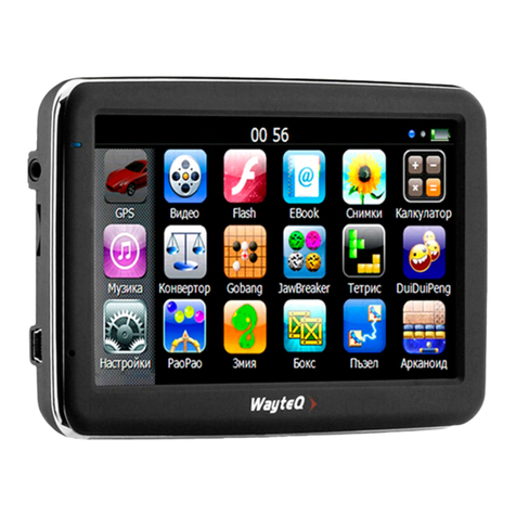
Mobile Data Terminal: M-Nav800
ConEx Sensor Monitoring
Qube Power Up Procedure
Verification
Completing the Installation
Driver ID system
Troubleshooting Section
Dimensions and Specifications
Technical Support
Global Positioning System (GPS)
Disclaimer
Contents

3
Fleet Tracking and Management
Cellular
Network
(SMS)
Qube4 –ATT
Global Positioning
System Satellites
Qube Fleet
Qtanium Fleet
Navman Wireless
Operations Center
Mobile iAVL Director

Recommended Installation Practices
4
Review this installationmanual to become familiar with all installation procedures and electrical wiring
requirements prior to starting the installation. This installation guide has been prepared to provide you with
details necessary to complete the Qube installation.
Use of proper tools and testing equipment is required. Never use a grounding style test light. Use only a
Digital Multi Meter (DMM) to test wires in the vehicle. It is strongly recommended that oneof the battery post
cables is disconnected or battery disconnect switch is engaged prior to making electrical connections.
The recommended method of electrical connections for the Qube is “Poke and Wrap”.“Poke and Wrap”
is described in detail later in this guide. It is critical to ensure that all electrical connections are properly
insulated with quality electrical tape. Do not use butt connectors, crimp connectors or any other means to
connect wires. Failing to ensure proper connections may result in warranty being voided and damage to the
Qube and/or the vehicle.
Ensure that all wiring is protected from heat sources and sharp metal edges and is routed in such
manner that it will not get damaged or pinched when vehicle components and trim are reinstalled.Run new
wiring along factory harnesses and secure with quality cable zip-ties. Be sure to leave a “service loop” near the
Qube, enough slack in the wiring to allow working room and strain relief.
The Qube is NOT waterproof, never mount the Qube in the engine compartment. When mounting the
Qube, determine best possible location under the dash and make sure that the Qube will be securely attached
using self-tapping screws or cable zip-ties. Do not force or jam the Qube into tight places instead of mounting
it. When mounting the Qube, do not obstruct any serviceable areas such as fuseboxes, etc. The Qube and its
wiring must be mounted away from any moving parts such as brake, gas, and clutch pedals and linkages.
Follow all safety guidelines outlined in this guide, the applicable Qube Installation Manual as well as
those set forth by industry and government.

Recommended Tools and Supplies
5
Basic Tools:
•Wire Strippers
•Connector Crimping Tool
•Panel Removal Tool
•Digital Multimeter (DMM)
•T-10S Security Torx Screwdriver
Basic Supplies:
•Ring Terminals
•Cable Zip-Ties
•Electrical Tape
•Spare Fuses (Mini 3A)
•Self-Tapping Screws
T-10S
Torx Screwdriver
Tamper Proof
Recommended Tool:
Gardner Bender
GS-394

Qube300 Hardware
6
To ensure professional installation, Navman Wireless
provides an install hardware kit for all new Qube
systems.
QubeInstallation Supplies Kit
To allow for quicker and easier installations, Navman
Wireless designed an all-in-one antenna system that
includes both GPS and cellular components built into
same housing.
GPS/Cellular Combination Antenna

Qube300 Hardware
7
Qube3 Box Contents:
T-10S Security Screws (3 pcs)
Power Harness
2-piece Anti-Tamper Cover
4 Mounting ScrewsCell Antenna
Connector
8-pin I/O
Cable Port B
4-pin Power
Port
MDT/Data
Port
(RJ45)
SIM card
Diagnostic LED’s
Green –Power (On/Off/Sleep)
Red –Cell (Online/Offline)
Orange –GPS (Fix/No Fix)
10-pin I/O
Cable Port A
GPS Antenna
Connector
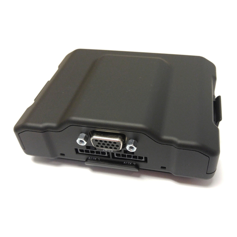
The Navman Wireless Qube300 is an Automatic Vehicle Location unit (AVL) that is installed into
fleet vehicles. It communicates with a server and allows vehicle information to be stored and
monitored.
It is a combined GPS (Global Positioning System) and communications product that contains:
•aGPS Receiver to provide accurate location data,
•a Cellular Modem that enables data to be transferred between the vehicle and the
server,
•an on-board microprocessorto allow data processing and storage, and external
communication.

Security Cover
8
T-10S Security Screws
T-10S Torx
Screwdriver
Required

Power Harness
9
Black - Ground
Pink* - Ignition
Red* - Constant +12/24V
*These connections must be fused (3A)
•RED wire –Uninterrupted Power Source (3A fuse)
•PINK wire –Primary Ignition /Switched Source (3A fuse)
•BLACK wire –Chassis Ground
*Power Harness prepped using the Install Kit

Identifying the Correct Wires
10
1. Remove any interior/under dash trim necessary to gain access to vehicle’s wiring as well as all
areas where interconnecting wire harnesses will need to be located.
2. Attach fuse holders to the Constant and Ignition wires of the Qube’s harness.
3. Individually isolate any wires in the Qube’s harnesses that will not be used during installation.
4. It is strongly recommended to locate and connect constant power and ignition wires at the
ignition key switch connector behind ignition key cylinder. (Note: If the ignition switchharness is not
accessible, amperage restriction exists, or the vehicle has an electronic starting system, constant power and ignition
connections can be made at the interior fusebox.)
5. Use a multimeter and the chart on next page to identify Constant and Ignition wires.

Identifying the Correct Wires
11
Vehicle’sConstant Power wire
The correct wire will have battery voltage +12V (or +24V) present at all times, even when the
ignition key is in off position or removed. Connect Qube’s red wire here.
Vehicle’s Ignition wire
The correct wire will have +12V (or +24V) present only when -- the key is in ON position, during
cranking and while motor is running. Connect Qube’s pink wire here.
Typical Ignition Key Cylinder
Note1: After appropriate wires have been identified, it is strongly recommended that oneof
the battery post cables is disconnected prior to making wire connections.
Note2: If the vehicle has amaster battery disconnect switch,Qube must be connected on the
battery (hot) side of that switch.
START
OFF
ACC
ON

Poke & Wrap solderless Connections
12
The recommended method of connecting wires is by soldering.
As an alternative, when working inside the cab or any
weatherproofenvironment, a “Poke & Wrap”method for
solder-less connections will be acceptable.
During the “Poke & Wrap”procedure use extreme caution not
to allow any exposed wires to come into direct/indirect
contact with the vehicle’s chassis or other exposed wires.
Strip. Use wire strippers or razor knifeto pull back/remove
about ¾ inch of insulation from the source wire in the
vehicle. Next, strip about 1” of insulation from your fuse
holder’s wire.
Divide. Use a sharp toolto divide exposed strands of the
source wire down the middle, creating a loop.
Poke. Insert fuse holder’s stripped wire through the loop in
the source wire. Squeeze the loop shut.
Twist. Twist tightly exposed lead of the fuse holder around
the bare section of vehicle’s source wire (4-6 wraps).
Lock. Next, bend the fuse holder wire back onto the wrapped
section. This step will act as the lock for the Poke & Wrap
type of wire connection.
Secure. Apply adequate amount of electrical tape to isolate
your connection. Wrap tightly. Finally, use a zip-tie to
completely secure the connection. This will ensure the
connection will not vibrate loose, or come apart after time.
Apply tamper seal to the zip-tie.
Do not use any nylon or vinyl butt connectors, t-taps,
1. Strip
2. Divide
3. Poke
4. Twist
5. Lock
6. Secure
Cable TieElectrical Tape
scotchloks, quick disconnects or fuse taps.

Chassis Ground Connection
13
•Connect theQube’s Ground wire (black)
to vehicle’s chassis.
•For a solid connection, use a ring tongue
terminal connector, star washer and a
self-tapping screw
•Do not ground under existing bolts that
hold brackets or panels in place.
•If the vehicle has a master battery
disconnect switch on the negative side,
run the black wire connection to the
uninterrupted sideof the switch or
directly to the negative terminal of the
battery.

Mounting the Antenna
14
GPS/Cell
Combination
Antenna
*View from under the dash
•Exposed install: Using the supplied double-sided tape pad, mount the antenna to the bottom corner of the
windshield. Make sure the correct side of antenna is facing out, into the sky.
•Covert install: Using the supplied double-sided tape pad, mount the antenna to a flat clean surface under
the passenger side of the dashboard –as high as possible, ideally, just under top dash cover and positioned
horizontally. Make sure the correct side of antenna is facing up, into the sky.
•Do not mount the GPS antenna under any metal surface or near the vehicle’s radio. Avoid mounting
antennas under dash in front of the drivers since they may place metal clipboards, laptops, etcon top of
dash and inadvertently block the GPS signal to the antenna. This antenna is NOT waterproof–do not
mount outside the vehicle.
*Customer representative will determine theappropriate method (exposed or covert) for mounting the
antenna.

Mobile Data Terminal: M-Nav800
15
Cradle Suction Mount
M-Nav800
Power/Data Cable
Power Adaptor
Mnav plugs into Data Port on Qube300
Route the M-Nav800 Power/Data cable from the Qube to the top of dashboard, where M-Nav800 will be mounted.
Use the supplied suction cup mount or the optional dashmount bracket to secure the device in place. Plug into the
Optional Panavise
hard-mount bracket
MDT/Data Port on the Qube300.

Mobile Data Terminal: M-Nav800
16
2 Screws
4 Screws
Install
Zip Tie
*In-Line Power Adaptor
Optional: 2 screws
for permanent mount

ConEx Sensor Monitoring
17

ConEx SensorMonitoring (cont.)
18
Digital Inputs DI-1 to DI-4
+12V
Door Pin (-) Dome Light
Digital IN
+12V
Door Pin (+) Dome Light
Digital IN

ConEx SensorMonitoring (cont.)
19
Digital Outputs DO-1 & DO-2
+12V
Green–Digital I/O-2
x
*Disconnect a circuit
+12V
Green–Digital I/O-2
*Activate a light or buzzer
85
86 30
87
87A
85
86 30
87
87A
The digital outputs will pull to ground and sink a maximum current of 250ma when activated. The outputs
have over-current trip protection and, if tripped, the output must be changed to OFF or have a power cycle to
reset the current trip.

ConEx SensorMonitoring (cont.)
20
Multi I/O-1 & I/O-2
Each Multi I/O can be configuredin one of 3 different operating modes: DigitalInput, Digital Output, or Analogue Input.
This manual suits for next models
1
Table of contents
Other TELETRAC NAVMAN GPS manuals
TELETRAC NAVMAN
TELETRAC NAVMAN Qtanium 100 User manual
TELETRAC NAVMAN
TELETRAC NAVMAN Qtanium 400 User manual
TELETRAC NAVMAN
TELETRAC NAVMAN iFace User manual

TELETRAC NAVMAN
TELETRAC NAVMAN iFace User manual
TELETRAC NAVMAN
TELETRAC NAVMAN Qtanium200 User manual

TELETRAC NAVMAN
TELETRAC NAVMAN Qtanium 100 User manual
TELETRAC NAVMAN
TELETRAC NAVMAN TM470 Series Installation guide
