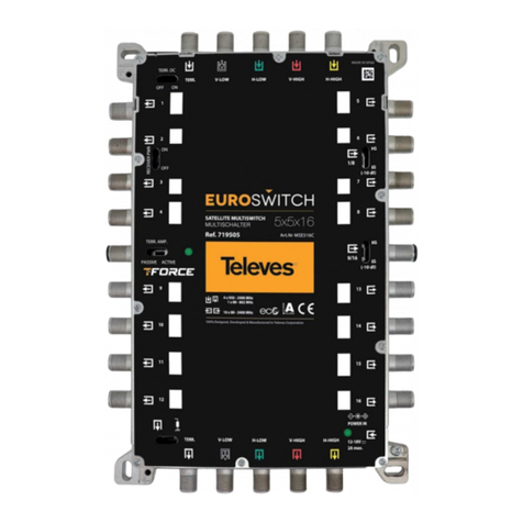
Televes EUROSWITCH MSW 17 Series User manual

EUROSWITCH
EUROSWITCH MSW 17x
EUROSWITCH AMPLIFIER 17x
https://qr.televes.com/A87724
EUROSWITCH MSW 17x
EUROSWITCH AMPLIFIER 17x
719801 - MSE178K 17x17x8
719802 - MSE1712K 17x17x12
719803 - MSE1716K 17x17x16
719804 - MSE1724K 17x17x24
719805 - MSE1732K 17x17x32
719809 - MSE1727V 17x17
RANGO DE PRODUCTOS GAMME DE PRODUITS PRODUCT RANGE GAMMA DEL PRODOTTO
Ref / Art. Nr. Descripción Description Description Descrizione
719801
MSE178K Euroswitch 17x17x8 17x17x8 Multiswitch 17x17x8 Euroswitch Multiswitch 17x17x8
719802
MSE1712K Euroswitch 17x17x12 17x17x12 Multiswitch 17x17x12 Euroswitch Multiswitch 17x17x12
719803
MSE1716K Euroswitch 17x17x16 17x17x16 Multiswitch 17x17x16 Euroswitch Multiswitch 17x17x16
719804
MSE1724K Euroswitch 17x17x24 17x17x24 Multiswitch 17x17x24 Euroswitch Multiswitch 17x17x24
719805
MSE1732K Euroswitch 17x17x32 17x17x32 Multiswitch 17x17x32 Euroswitch Multiswitch 17x17x32
719809
MSE1727V Amplicador 17x17 17x17 Amplier 17x17 Amplier Amplicatore 17x17
593203 2,0A
Fuente de alimentación 12V PSU 12V PSU 12V Alimentatore 12V
732101 0,8A
732210 1.5A
732802 2,8A
732001 2,0A
Fuente de alimentación 18V PSU 18V PSU 18V Alimentatore 18V
732010

ISTRUZIONI IMPORTANTI PER LA SICUREZZA
Instalación segura
1. Lea las instrucciones antes de manipular o conectar el equipo. Conserve estas instrucciones. Preste
atención a todas las advertencias. Siga todas las instrucciones.
2. Limpie la unidad sólo con un paño seco.
3. No utilice este aparato cerca del agua. El aparato no debe ser expuesto a caídas o salpicaduras de
agua, no situar objetos llenos de líquidos sobre o cerca del aparato tales como vasos si no tiene la
suciente protección.
4. No bloquee las aberturas de ventilación. Realizar la instalación de acuerdo con las instrucciones del
fabricante. Dejar un espacio libre alrededor del aparato para proporcionar una ventilación adecuada.
5. No situar el equipo en ambientes de humedad elevada.
6. Noinstalar cercadefuentesdecalor talescomo radiadores,registros decalor, estufasuotros aparatos
(incluyendo amplicadores) que produzcan calor. No situar sobre el aparato fuentes de llama
desnuda, tales como velas encendidas.
7. No situar el equipo donde pueda estar sometido a fuertes vibraciones o sacudidas.
8. Utilice solamente los aditamentos/accesorios especicados por el fabricante.
Utilización segura del equipo
• La temperatura ambiente no debe superar los 45°C.
• Solicite todas las reparaciones a personal de servicio cualicado. Solicite una reparación cuando
el aparato se haya dañado de cualquiera forma, como cuando se ha derramado líquido o han
caído objetos dentro del aparato, el aparato ha sido expuesto a la lluvia o humedad, no funciona
normalmente, o haya sufrido una caída.
IMPORTANTES INSTRUCCIONES DE SEGURIDAD
ES
FR IT
IMPORTANT SAFETY INSTRUCTIONS
EN
Safe installation
1. Read these instructions before handling or connecting the equipment. Keep these instructions.
Heed all warnings. Follow all instructions.
2. Clean only with dry cloth.
3. Do not use this apparatus near water. Apparatus shall not be exposed to dripping or splashing and
no objects lled with liquids, such as glasses, shall be placed on the apparatus.
4. Do not block any ventilation openings. Install in accordance with the manufacturer’s instructions.
Please allow air circulation around the equipment.
5. Do not place the equipment in a highly humid environment.
6. Do not install near any heat sources such as radiators, heat registers, stoves, or other apparatus
(including ampliers) that produce heat. Do not place naked ames, such as lighted candles on or
near the product.
7. Do not place the equipment in a place where it can suer vibrations or shocks.
8. Only use attachments/accessories specied by the manufacturer.
Safe operation of equipment
• Ambient temperature should not be higher than 45ºC.
• Refer all servicing to qualied service personnel. Servicing is required when the apparatus has been
damaged in any way, such as liquid has been spilled or objects have fallen into the apparatus, the
apparatus has been exposed to rain or moisture, does not operate normally, or has been dropped.
Installation sécurisée
1. Lire les instructions avant de manipuler ou de brancher l’appareil. Conserver ces instructions. Tenir
compte de tous les avertissements. Suivre toutes les instructions.
2. Nettoyer l’appareil avec un chion sec uniquement.
3. Ne pas utiliser cet appareil à proximité de l’eau. L’appareil ne doit pas être exposé à des gouttes ou à
des éclaboussures et aucun objet contenant du liquide, tel un vase, ne doit être placé sur l’appareil ou
à proximité de celui-ci, sauf si l’appareil est convenablement protégé.
4. Ne pas obstruer les ouvertures de ventilation. Eectuer l’installation conformément aux instructions
du fabricant. Laisser un espace tout autour de l’appareil pour assurer une ventilation adéquate.
5. Ne pas placer le produit dans un environnement à forte humidité.
6. Nepas installerleproduitàproximitéde sourcesde chaleurtellesqueradiateurs,bouches dechaleur,
poêles ou autres appareils (y compris les amplicateurs) qui produisent de la chaleur. Ne pas placer
de sources de amme nue, telles que des bougies allumées, sur l’appareil.
7. Ne pas placer le produit dans un lieu où il pourrait être soumis à de fortes vibrations ou à des chocs.
8. Utiliser uniquement les pièces complémentaires/accessoires spéciés par le fabricant.
Utilisation sécuritaire du matériel
• La température ambiante ne doit pas dépasser 45°C.
• Faire eectuer toutes les réparations par du personnel qualié. L’entretien est nécessaire lorsque
l’appareil a été endommagé de quelque manière que ce soit, par exemple lorsque le cordon
d’alimentation ou la prise est endommagé, lorsqu’un liquide a été renversé ou que des objets
sont tombés dans l’appareil, lorsque l’appareil a été exposé à la pluie ou à l’humidité, lorsqu’il ne
fonctionne pas normalement ou suite à une chute.
INSTRUCTIONS IMPORTANTES DE SÉCURITÉ
Installazione sicura
1. Leggere le istruzioni prima di maneggiare o collegare l’apparecchiatura. Conserva queste istruzioni.
Presta attenzione a tutti gli avvertimenti. Segui tutte le istruzioni.
2. Pulire solo con un panno asciutto.
3. Non utilizzare questa apparecchiatura vicino all’acqua. Il dispositivo non deve essere esposto a
cadute o spruzzi d’acqua, se non si dispone di una protezione suciente non collocare oggetti pieni
di liquidi come i bicchieri, sopra o vicino al dispositivo.
4. Non ostruire le feritoie di ventilazione. Eseguire l’impianto secondo le istruzioni del produttore.
Lasciare uno spazio libero intorno all’apparecchio per fornire un’adeguata ventilazione.
5. Non posizionare l’apparecchiatura in ambienti ad alta umidità.
6. Non lasciare l’apparecchiatura vicino a fonti di calore come radiatori, termosifoni, stufe o altri
apparecchi (inclusi gli amplicatori) che producono calore. Non collocare fonti di calore o amme
libere sull’apparecchio, come candele accese.
7. Non collocare l’apparecchiatura in zone ove possa essere soggetta a forti vibrazioni o urti.
8. Utilizzare solo accessori specici del produttore.
Uso sicuro delle attrezzature
• La temperatura ambiente non deve superare 45°C.
• Far eseguire tutte le riparazioni dal personale di assistenza qualicato. Richiedere la riparazione
qualora l’apparato sia stato danneggiato in qualunque modo, oppure vi sia stato versamento di
liquidi o per cadute di oggetti nell’apparecchio, o ancora se l’apparato è stato esposto a pioggia o
umidità, nel caso in cui non funzioni correttamente o sia caduto.
ES
Seguridad eléctrica
1El equipo cumple los
requerimientos del marcado CE
EN
Electrical safety symbols
1The equipment complies with the
CE mark requirements.
FR
Sécurité électrique
1Le produit est conforme aux
exigences du marquage CE.
IT
Sicurezza elettrica
1L’apparecchiatura è conforme ai
requisiti del marchio CE.
2Equipo diseñado para uso en
interiores. 2Equipment designed for indoor
use. 2Produit conçu pour l’intérieur. 2Attrezzatura progettata per uso
interno.
1
CAUTION
2
Simbología/ Symbology / Symbologie / Simbologia

1
1
33
4
5
33
EUROSWITCH MSW 17x
6
(*)
(*)
2
2
7
PASSIVE ACTIVE
TERR. AMP.
Switch 1
Switch 2
TERR.
V-LOW
12V
H-LOW
TERR.
1
LG
(-10 dB)
HG
Conexiones y controles / Connections and controls / Raccordements et contrôles / Connessioni e controlli
ES
1. Conectores de entrada / salida de líneas tron-
cales de satélite.
2. Conector de entrada / salida de línea troncal
terrestre.
3. Conectores de salida de usuario.
4. Jack de alimentacion DC.
5. Interruptor amplicador terrestre TForce
(Switch 1).
6. Interruptor autocarga líneas troncales (Switch
2).
7. Conexión para toma de tierra.
(*) No disponible.
Nota:
SWITCH 1
Control del amplicador TForce de la señal terrestre
en las salidas de usuario :
Modo activo ( TForce ON ) : 0dB.
Modo pasivo ( TForce OFF ) : -30dB.
Los niveles expresados son valores aproximados y son
relativos al nivel de señal en la troncal terrestre.
SWITCH 2
Autocarga ON : conmutador aislado o conmutador
terminal en una instalación.
Autocarga OFF : conmutador no aislado ni terminal
de una instalación.
Nota:
El modo activo ( TForce ON ) y Autocarga ON requie-
ren que algún elemento de la instalación aporte ali-
mentación a la misma.
EN
1. Input satellite connectors/Output to satellite
trunk lines
2. Input terrestrial connector/Output to terrestrial
trunk line
3. Output users connectors
4. DC power supply input jack
5. TForce terrestrial amplier switch (Switch 1).
6. Trunk lines autoload switch (Switch 2).
7. Ground connection
(*).- Not available
Note:
SWITCH 1
TForce amplier control of the terrestrial signal in the
user outputs:
Active mode (TForce ON): 0 dB
Passive mode (TForce OFF): -30 dB
The values are approximate and are relative to the
signal level in the terrestrial trunk.
SWITCH 2
Autoload ON: Single Multiswitch installation (stand
alone) or terminal Multiswitch in a cascade.
Autoload OFF: Multiswitch installed in the middle of a
cascade.
Note:
Active Mode (TForce ON) and Autoload ON require
that an element in the installation powers it up.
FR
1. Connecteurs entrée/sortie pour les polarités
satellites
2. Connecteur entrée/sortie pour le signal terres-
tre.
3. Connecteurs de sortie utilisateur.
4. Prise d’alimentation DC.
5. Interrupteur d’amplicateur terrestre TForce
(Switch 1).
6. Commutateur d’auto-charge. passage/terminal
(Switch 2).
7. Mise à la terre.
(*) Pas disponible.
Note:
SWITCH 1
Contrôle de l’amplicateur TForce du signal terrestre
en sorties utilisateur :
Mode actif ( TForce ON ) : 0dB.
Mode passif ( TForce OFF ) : -30dB.
Les valeurs de niveau données sont des valeurs appro-
ximatives et dépendent du niveau d’entrée du signal
terrestre.
SWITCH 2
Charge-Auto ON : interrupteur d’isolation ou inte-
rrupteur terminal dans une installation.
Charge-Auto OFF : interrupteur de Ligne passante
dans une installation.
Nota:
Le mode actif ( TForce ON ) et l’auto-chargement ON
exigent qu’un élément de l’installation lui fournisse
du courant.
IT
1. Connettori di ingresso/uscita delle polarità per
il collegamento satellitare.
2. Connettore di ingresso/uscita per il segnale
terrestre.
3. Connettori per le derivate utente.
4. Jack di alimentazione DC.
5. Interruttore dell’amplicatore terrestre TForce
(Switch 1).
6. Interruttore per abilitare/disabilitare la resisten-
za di chiusura elettronica (Switch 2).
7. Connessione per messa a terra.
(*).- Non disponibile.
Nota:
SWITCH 1
Controllo dell’amplicatore del segnale terrestre TFor-
ce nelle uscite utente :
Modo attivo ( TForce ON ) : 0dB.
Modo passivo ( TForce OFF ) : -30dB.
I livelli espressi sono valori approssimativi e sono rela-
tivi al livello del segnale nel montante terrestre.
SWITCH 2
Carico elettronico ON : per isolare il dispositivo o ren-
derlo terminale in una cascata.
Carico elettronico OFF : per non isolare il dispositivo o
non renderlo terminale in una cascata.
Nota:
La modalità attiva (TForce ON) e carico elettronico
ON richiedono che alcuni elementi dell’impianto for-
niscano alimentazione.

TERR.
IN SAT A
V-LOW H-LOW V-HIGH H-HIGH
IN SAT B
V-LOW H-LOW V-HIGH H-HIGH
IN SAT C
V-LOW H-LOW V-HIGH H-HIGH
IN SAT D
V-LOW H-LOW V-HIGH
OUT SAT A
TERR. V-LOW H-LOW V-HIGH H-HIGH
OUT SAT B
V-LOW H-LOW V-HIGH H-HIGH
OUT SAT C
V-LOW H-LOW V-HIGH H-HIGH
OUT SAT D
V-LOW H-LOW V-HIGH H-HIGH
MADE IN SPAIN
Art.Nr MSE1727V
Ref. 719809
17x17
AMPLIFIER
VERSTÄRKER
16 x 950 - 2400 MHz
1 x 88 - 862 MHz
H-HIGH
SLOPE
ADJUST
GAIN
ADJUST
OFF ON
TERR. DC
100% Designed, Developed & Manufactured in Televes Corporation
12-18V
3A max.
POWER IN
1
1
4
2
5
3
EUROSWITCH AMPLIFIER 17x
2
6
ES
1. Conectores de entrada / salida de líneas troncales
de satélite.
2. Conector de entrada / salida de línea troncal te-
rrestre.
3. Jack de alimentacion DC.
4. Interruptor alimentación línea troncal terrestre
(Switch TERR. DC.).
5. Ajustes de nivel de ganancia y pendiente de las
señales de salida.
6. Conexión para toma de tierra.
Nota:
SWITCH TERR.DC
Permite aportar alimentación a la línea troncal terrestre
para alimentar a los elementos de cabecera instalados.
EN
1. Input satellite connectors/Output to satellite trunk
lines
2. Input terrestrial connector/Output to terrestrial
trunk line
3. DC power supply input jack
4. Terrestrial trunk line power-up switch (SwitchTERR.
DC.).
5. Gain level and slope adjusting of output signals
6. Ground connection
Note:
SWITCH TERR.DC
Allows powering the terrestrial trunk line to power the
installed head end elements.
FR
1. Connecteurs d’entrée/sortie des polarités satellites.
2. Connecteur d’entrée/sortie de la ligne terrestre.
3. Prise d’alimentation DC.
4. Interrupteur de ligne terrestre (Switch TERR. DC.).
5. Réglages de gain et de pente des signaux de sortie.
6. Raccordement de mise à la terre.
Nota:
SWITCH TERR.DC
Permet la téléalimentation, sur la ligne terrestre, des élé-
ments installés en réception.
IT
1. Connettori di ingresso/uscita delle polarità per il
collegamento satellitare.
2. Connettore di ingresso/uscita per il segnale terres-
tre.
3. Jack di alimentazione DC.
4. Interruttore di alimentazione del montante terres-
tre (Switch TERR. DC.).
5. Regola il guadagno e la pendenza dei segnali di
uscita.
6. Connessione per messa a terra.
Nota:
SWITCH TERR.DC
Consente di dare alimentazione al montante terrestre
per alimentare eventuali apparati installati nella cen-
trale di testa.
TERR.
TERR. V-LOW
A
OFF ON
TERR. DC
TERR.D.C.
TERR.V-LOWH-LOWH-HIGH
V-HIGH V-LOWH-LOWH-HIGH
V-HIGH
TERR.
SLOPE
ADJUST
GAIN
ADJUST
VDE
V-LOWH-LOWH-HIGH
V-HIGH V-LOWH-LOWH-HIGH
V-HIGH
MADEIN SPAIN
POWER
DC
DC
12 ...18 V
3 A
719801 - MSE1708K
719802 - MSE1712K
719803 - MSE1716K
719804 - MSE1724K
719805 - MSE1732K
719809- MSE1727V
500 mA/Terr. Trunk line
500 mA/Sat. Trunk line
500 mA/Terr. Trunk line
500 mA/Sat. Trunk line
Alimentación / Powering / Alimentation / Alimentazione
12 ...18 V
3 A

margin, equally distributed throughout it.
In case of large installations that require the
use of ampliers, these will be the reference
elements to place the power supplies.
The installation can also be powered up by
other means, the satellite trunk lines of some
of their elements. In all cases, the maximum
allowed current in each satellite trunk line
must be taken into account.
The terrestrial trunk line is isolated of the
satellite trunk lines and does not provide
power to the installation, though it allows
voltage pass to power up installed Head-end
elements (BOSS antenna or preamplier).
Such powering could be provided by the
installation ampliers, activating to ON the
Switch“TERR DC”(4).
When the installation does not have any
power supply, the Multiswitch will continue
to correctly working, assuming that the
signals in the trunk lines are powered up/
provided by other means. in this case, neither
the active mode of the Tforce Terrestrial
amplier will be available (passive mode
working northeautoload of the trunk lines.
FR
Tous les éléments de l’installation, les com-
mutateurs et les amplicateurs, qui dispo-
sent d’une alimentation électrique, raccor-
dent cette source aux lignes principales
satellites, pour s’alimenter d’une part, et
d’autre part, pour alimenter d’autres élé-
ments de l’installation qui ne disposent pas
d’une alimentation électrique (par exemple
d’autres commutateurs ou amplicateurs)
ainsi que les LNB.
En bref, les alimentations électriques dis-
ponibles dans l’installation sont partagées
par tous les éléments de l’installation, ce
qui permet de minimiser les sources né-
cessaires. Le dimensionnement du nombre
d’alimentations électriques à installer est
eectué en fonction de la consommation
totale de l’installation, avec la marge de sé-
curité correspondante, répartie de manière
égale sur l’ensemble de l’installation. Dans le
cas des grandes installations qui nécessitent
l’utilisation d’amplicateurs, ces derniers se-
ront les éléments privilégiés pour le position-
nement des alimentations.
L’installation peut être alimentée directe-
ment par les lignes de polarité satellite d’un
de ses éléments. Dans tous les cas, le courant
maximal admissible pour chacune des lignes
satellites doit être respecté.
La ligne principale terrestre est isolée des
lignes principales satellites et n’alimente pas
l’installation, bien qu’elle permette le passa-
ge du courant pour alimenter les éléments
de réception (antenne de tête ou préampli-
cateur). Ce courant peut être délivré par les
amplicateurs de l’installation, en activant
le commutateur “TERR”. DC.”” (4), voir gure
page 14.
Si l’installation ne dispose pas d’une ali-
mentation électrique, les commutateurs
Euroswitch continueront à fonctionner co-
rrectement (on suppose que les signaux des
ES
Todos los elementos de la instalación, tanto
conmutadores como amplicadores, que
dispongan de una fuente de alimentación,
conectan dicha fuente a las líneas troncales
de satélite, para por un lado alimentarse a si
mismos, y por otro, proporcionar alimenta-
ción a otros elementos de la instalación que
carezcan de fuente de alimentación (por
ejemplo otros conmutadores ó amplicado-
res) y también a los LNBs.
En resumen, las fuentes de alimentación dis-
ponibles en la instalación son compartidas
por todos los elementos de la misma, lo que
permite minimizar las fuentes necesarias. El
dimensionamiento del número de fuentes a
instalar se realizará en función del consumo
total de la instalación, con el correspondien-
te margen de seguridad, repartiéndose de
manera equitativa a lo largo de la misma. En
el caso de instalaciones grandes que nece-
siten la utilización de amplicadores, éstos
serán los elementos de preferencia a la hora
de situar las fuentes de alimentación.
La instalación también puede ser alimenta-
da por otros medios directamente a través
de las líneas troncales de satélite de alguno
de sus elementos. En todos los casos se ha
de respetar el máximo de corriente admisi-
ble por cada una de las líneas troncales de
satélite.
La línea troncal terrestre está aislada de las
troncales de satélite y no aporta alimen-
tación a la instalación, aunque si permite
el paso de corriente para alimentar a los
elementos de cabecera instalados ( antena
boss ó preamplicador). Dicha corriente po-
dría ser proporcionada por los amplicado-
res de la instalación, activando el interruptor
“TERR. DC.”(4), ver gura en página 14.
En el caso de que la instalación no dispon-
ga de ninguna fuente de alimentación, los
conmutadores Euroswitch continuarán fun-
cionando correctamente ( se supone que las
señales en la líneas troncales son alimenta-
das / proporcionadas por otros medios ). En
este caso, el modo activo del amplicador
terrestreTforce no estará disponible (funcio-
namiento en modo pasivo) como tampoco
lo estará la función de autocarga de las lí-
neas troncales.
EN
All the elements of the installation, whether
Multiswitches or ampliers which have a
power supply, connect this power supply
to the satellite trunk lines. As a result of this,
they power themselves up and besides, they
provide power supply to other elements
in the installation lacking a power source,
like for instance other Multiswitches or
ampliers and also the LNBs.
The power supplies available in the
installation are shared by all its elements,
which allow to minimize their number.
The dimensioning of the number of power
supplies will be carried out as a function
of the total power consumption of the
installation, with the corresponding security
lignes principales sont alimentés/fournis par
d’autres moyens). Dans ce cas, le mode actif
de l’amplicateur terrestre Tforce ne sera pas
disponible (fonctionnement en mode pas-
sif) et la fonction d’auto-charge du passage
ne sera pas disponible.
IT
Tutti gli elementi dell’impianto, sia i mul-
tiswitches che gli amplicatori, a cui si colle-
ga un alimentatore, forniscono alimentazio-
ne ai montanti di collegamento del satellite,
per alimentare loro stessi, da un lato, e per
fornire alimentazione ad altri dispositivi
dell’impianto a cui manca un alimentatore
(ad esempio altri switch o amplicatori) e
anche gli LNB.
In sintesi, gli alimentatori disponibili
nell’impianto sono condivisi da tutti gli
elementi dello stesso, il che consente di ri-
durre al minimo gli alimentatori necessari.
Il dimensionamento del numero di alimen-
tatori da installare sarà eettuato in base al
consumo totale dell’impianto, con il corris-
pondente margine di sicurezza, distribuito
equamente. Nel caso di grandi impianti che
richiedono l’uso di amplicatori, questi sa-
ranno gli elementi che avranno la priorità
quando si posizionano gli alimentatori.
L’impianto può anche essere alimentato con
altri dispositivi, direttamente attraverso le
linee montanti satellitari di collegamento di
alcuni dei suoi elementi. In tutti i casi, deve
essere rispettata la massima corrente am-
missibile per ciascun montante di collega-
mento satellitare.
Il montante terrestre è isolato da quelli
satellitari e non fornisce alimentazione
all’impianto, sebbene consenta il passaggio
di corrente per alimentare i dispositivi della
centrale di testa (antenna boss o preampli-
catore). Questa corrente potrebbe essere
fornita dagli amplicatori dell’impianto,
attivando “TERR. DC ”(4), vedere la gura a
pagina 14.
Nel caso in cui l’impianto non disponga di
un alimentatore, i multiswitches Euroswitch
continueranno a funzionare correttamente
(si presume che i segnali sulle linee di co-
llegamento siano alimentati/forniti con altri
dispositivi). In questo caso, la modalità attiva
dell’amplicatore terrestre Tforce non sarà
disponibile (funzionamento in modalità pas-
siva), né la funzione di chiusura elettronica.

TERR.
INSATA
V-LOWH-LOW V-HIGH H-HIGH
INSATB
V-LOWH-LOW V-HIGH H-HIGH
INSATC
V-LOWH-LOW V-HIGH H-HIGH
INSATD
V-LOWH-LOW V-HIGH
OUTSATA
TERR. V-LOWH-LOWV-HIGH H-HIGH
OUTSATB
V-LOWH-LOWV-HIGH H-HIGH
OUTSATC
V-LOWH-LOWV-HIGH H-HIGH
OUTSATD
V-LOWH-LOWV-HIGH H-HIGH
MADEINSPAIN
Art.NrMSE1727V
Ref.719809
17x17
AMPLIFIER
VERSTÄRKER
16x950 - 2400 MHz
1x88 - 862 MHz
H-HIGH
SLOPE
ADJUST
GAIN
ADJUST
OFFON
TERR.DC
100%Designed,Developed & Manufactured in Televes Corporation
12-18V
3Amax.
POWERIN
TERR.
INSATA
V-LOWH-LOW V-HIGHH-HIGH
INSATB
V-LOWH-LOW V-HIGHH-HIGH
INSATC
V-LOWH-LOW V-HIGHH-HIGH
INSATD
V-LOWH-LOW V-HIGH
OUTSATA
TERR. V-LOWH-LOWV-HIGH H-HIGH
OUTSATB
V-LOWH-LOWV-HIGH H-HIGH
OUTSATC
V-LOWH-LOWV-HIGH H-HIGH
OUTSATD
V-LOWH-LOWV-HIGH H-HIGH
MADEINSPAIN
Art.NrMSE1727V
Ref.719809
17x17
AMPLIFIER
VERSTÄRKER
16x950 - 2400 MHz
1x88 - 862 MHz
H-HIGH
SLOPE
ADJUST
GAIN
ADJUST
OFFON
TERR.DC
100%Designed,Developed & Manufactured in Televes Corporation
12-18V
3Amax.
POWERIN
TERR.
GAIN
ADJUST
OFF ON
TERR. DC
TERR.
1
6
3
2
5
7
4
8
V-LOW H-LOW V-HIGH H-HIGH
INSATA
V-LOW H-LOW V-HIGH H-HIGH
INSATB
V-LOW H-LOW V-HIGH H-HIGH
INSATC
Art.NrMSE1716K
Ref.719803
17x17x16
SATELLITEMULTISWITCH
MULTISCHALTERx
14
11
10
13
15
12
16
9
V-LOW H-LOW V-HIGH H-HIGH
INSATD
TERR.
V-LOW H-LOW V-HIGH H-HIGH
OUTSATA
V-LOW H-LOW V-HIGH H-HIGH
OUTSATB
V-LOW H-LOW V-HIGH H-HIGH
OUTSATC
V-LOWH-LOW V-HIGH H-HIGH
OUTSATD
PASSIVE ACTIVE
TERR.AMP.
MADEINSPAIN
12-18V
3Amax.
POWERIN
16x950 - 2400 MHz
1x88 - 862 MHz
16x88 - 2400 MHz
TERR.
1
6
3
2
5
7
4
8
V-LOW H-LOW V-HIGH H-HIGH
INSATA
V-LOW H-LOW V-HIGH H-HIGH
INSATB
V-LOW H-LOW V-HIGH H-HIGH
INSATC
Art.NrMSE1716K
Ref.719803
17x17x16
SATELLITEMULTISWITCH
MULTISCHALTER
14
11
10
13
15
12
16
9
V-LOW H-LOW V-HIGH H-HIGH
INSATD
TERR.
V-LOW H-LOW V-HIGH H-HIGH
OUTSATA
V-LOW H-LOW V-HIGH H-HIGH
OUTSATB
V-LOW H-LOW V-HIGH H-HIGH
OUTSATC
V-LOW H-LOW V-HIGH H-HIGH
OUTSATD
PASSIVE ACTIVE
TERR.AMP.
MADEINSPAIN
12-18V
3Amax.
POWERIN
16x950 - 2400 MHz
1x88 - 862 MHz
16x88 - 2400 MHz
TERR.
GAIN
ADJUST
OFF ON
TERR. DC
2
732802
MS-NT1228
719809
MSE1727V
719803
MSE1716K
LNB
QUATTRO
719803
MSE1716K 719803
MSE1716K
719803
MSE1716K
x5
732802
MS-NT1228
719809
MSE1727V
Alimentado desde las líneas troncales / Alimentation par les lignes principales / Powered from trunk lines / Alimentato dalle linee del montante
17x
Sistema de multiswitches en cascada / Installation de multiswitches en cascade / Cascade multiswitches installation / Sistema di multiswitches in cascata
17x
x6
Fabricante / Manufacturer / Fabricant / Produttore : Televés S.A.U. Rúa B. de Conxo, 17 - 15706 Santiago de Compostela, A Coruña. Spain www.televes.com
DECLARACIÓN DE CONFORMIDAD DECLARATION OF CONFORMITY DECLARAÇÃO DE CONFORMIDADE DECLARATION DE CONFORMITE DICHIARAZIONE DI
CONFORMITÀ DEKLARACJA ZGODNOŚCI KONFORMITÄTSERKLÄRUNG ΠΙΣΤΟΠΟΙΗΤΙΚΟ ΣΥΜΜΟΡΦΩΣΗΣ FÖRSÄKRAN OM ÖVERENSSTÄMMELSE
ДЕКЛАРАЦИЯ СООТВЕТСТВИЯ
https://doc.televes.com
2023 © Copyright, Televés S.A.U.
TERR.
1
6
3
2
5
7
4
8
V-LOW H-LOW V-HIGH H-HIGH
INSAT A
V-LOW H-LOW V-HIGH H-HIGH
INSAT B
V-LOW H-LOW V-HIGH H-HIGH
INSAT C
Art.Nr MSE1716K
Ref.719803
17x17x16
SATELLITEMULTISWITCH
MULTISCHALTER
14
11
10
13
15
12
16
9
V-LOW H-LOW V-HIGH H-HIGH
INSAT D
TERR.
V-LOW H-LOW V-HIGH H-HIGH
OUTSAT A
V-LOW H-LOW V-HIGH H-HIGH
OUTSAT B
V-LOW H-LOW V-HIGH H-HIGH
OUTSAT C
V-LOWH-LOW V-HIGH H-HIGH
OUTSAT D
PASSIVE ACTIVE
TERR.AMP.
MADEINSPAIN
12-18V
3Amax.
POWERIN
16x 950 - 2400 MHz
1x 88 - 862 MHz
16x 88 - 2400 MHz
SAT STB
PASSIVE ACTIVE
TERR. AMP.
LNB
QUATTRO
719801 - MSE178K
719802 - MSE1712K
719803 - MSE1716K
719804 - MSE1724K
719805 - MSE1732K
732802
MS-NT1228
1
1234
123
+ 15 mm
Modo terminal / Stand alone / Mode terminal
Modalità terminale
Ejemplos de aplicación / Examples of
implementation /
Exemples d’application
/
Esempi di applicazione
Modo de instalación / Installation mode / Mode d’installation /
Modalità di installazione
This manual suits for next models
13
Table of contents
Other Televes Switch manuals

Televes
Televes SWUM-100-8 User manual

Televes
Televes EUROswitch 9x Series User manual

Televes
Televes EasyF User manual

Televes
Televes EUROswitch 5x User manual

Televes
Televes MULTRIX MS94NG User manual

Televes
Televes MS5800EQ User manual

Televes
Televes SWUM-1000-POE+ User manual

Televes
Televes MS54NG User manual

Televes
Televes 769146 User manual

Televes
Televes MS5120EQ User manual