manuals.online logo
Brands
  1. Home
  2. •
  3. Brands
  4. •
  5. Telguard
  6. •
  7. Security System
  8. •
  9. Telguard T-1630M Classic User manual

Telguard T-1630M Classic User manual

TELGUARD CLASSIC
QUICK INSTALLATION GUIDE
MODELS: T-1630M, T-1630MA, T-1110M, T-1210M, T-3100UL
WIRING DIAGRAM
RJ31X
HOST C/C
PREMISE
PHONES
INCOMING
TELCO
SIGPATH0.VSD
2
3
4
5
67
T
GREEN
R
RED
R1
BROWN
T1
GREY
8
T1 T R
R1
J1
T1 T R
R1
J2
Telco Voltage
Measurement
House Phone
Current
Measurement
Dialer Current
Measurement
1
Internal Circuitry
Telco Dialer
T1 T R R1
TELGUARD
The TELGUARD has to be the first device on the incoming telco line. No
telco device can be in front of or in parallel with the TELGUARD or a Line Fault
condition will occur.
TELULAR CORPORATION
TEST MODE 55# PROGRAMMING
(MOTOROLA CELLULAR HANDSET REQUIRED)
1. Power down unit and insert jumper JP0 (upper left-hand corner of
PCB).
2. Power up unit without the cellular handset being attached.
3. Wait about 30 seconds for unit to completely power up.
4. Attach cellular handset to the transceiver and power handset up.
5. The handset will display randomly flashing numbers.
6. Press the #key, the handset will display US’, now press 55 #.
7. The handset will display the System ID (SID) Number.
Typically, the only programming changes required are as follows:
Entry 01 5 Digit System ID.
Entry 03 10 Digit Cellular Phone Number.
Entry 06 2 Digit Group ID Mark.
The star key (*) advances you through the programming locations.
Numbers in BOLD are Factory Defaults.
NAM Location: Example:
01 - System ID Number (SID) 00042 Press *
02 - A Option Byte 10101001 Press *
03 - 10 Digit Cellular Phone Number 941-910-9911 Press *
04 - Station Class Mark (SCM) 08 Press *
05 - Access Overload Class (AOC) 15 Press *
06 - Group ID Mark (GIM) 10 Press *
07 - Security Code 000000 Press *
08 - Unlock Code 123 Press *
09 - Service Level 004 Press *
10 - B Option Byte 00000101 Press *
11 - C Option Byte 00000000 Press *
12 - Initial Paging Channel (IPCH) 0333 or 0334 Press *
13 - Initial Paging Channel for System A 0333 Press *
14 - Initial Paging Channel for System B 0334 Press *
15 - Number of Dedicated Paging Channels 021 Press *
16 - D Option Byte 10111011 Press *
8. The handset will display “ /“ in the upper right-hand corner of the
display.
9. Power down the handset and unplug it.
10. Put jumper JP4 In for B carrier. Put jumper JP4 Out for A carrier.
11. Remove jumper JP0 and reset unit by powering it down and back up
again.
TELGUARD QUICK INSTALLATION GUIDE.DOC 05/21/98 Technical Support: 8:00AM – 5:00PM EST 800-229-2326
SAVE A TRIP!
CONFIRM THAT CELLULAR SERVICE HAS BEEN
ACTIVATED PRIOR TO INSTALLATION.
FIVE STEP INSTALLATION SUMMARY
STEP 1: Confirm Voice Communication Over Cellular.
(Reference Step 1 in Installation Manual)
(1) Locate unit.
(2) Connect and temporarily place antenna.
(3) Connect lineman’s buttset or cellular handset.
(4) Measure maximum signal strength for best antenna
placement.
(5) Make call over celluar to ensure minumum noise level.
(6) Remove lineman’s buttset/cellular handset.
STEP 2: Transmit Alarm Signals Over Cellular.
(Reference Step 2 in Installation Manual)
(1) Prepare C/C.
(2) Connect C/C to TELGUARD Jack 2.
(3) Verify cellular transmissions.
STEP 3: Connect Incoming Telco Line.
(Reference Step 3 in Installation Manual)
(1) Be sure TELGUARD is the first device on the incoming
phone line.
(2) Connect RJ31X to TELGUARD Jack 1 and check switch
to telco.
(3) Disconnect incoming telco at Jack 1 and check switch to
cellular.
(4) Reconnect incoming telco at Jack 1 and check switch back
to telco.
STEP 4: Connect Supervisory Trip Outputs.
(Reference Step 4 in Installation Manual)
(1) Decide on a supervisory trip output strategy.
(2) Connect trip outputs.
(3) Check trips to C/C.
STEP 5: Complete the Installation.
(Reference Step 5 in Installation Manual)
(1) Enable the Automatic Self-Test (if appropiate).
(2) Enable the Comms Fail Feature (if appropiate).
(3) Check all jumper settings.
(4) Permanently mount and properly ground the TELGUARD
chassis.
(5) Disconnect the 10 dB attenuator (if used).
BUTTSET NAM PROGRAMMING
1.Power unit down, insert jumper JP8, power unit back up again.
2.Clip buttset on Tand RTest Points on right hand edge of PCB.
3. Once LEDs start to alternate, put buttset in talk mode and press 8.
4. Wait for ASTC LED to come on (you are in location 01).
NAM Location: Example:
01 - System ID Number (SID) 00042 Press *#
02 - Cellular Area Code 352 Press *#
03 - Cellular Phone Number 111-0111 Press *#
04 - Station Class Mark 08 Press *#
05 - Access Overload Class 15 Press *#
06 - Group ID Number 10 Press *#
07 - Security Code 000000 Press *#
08 - Unlock Code 123 Press *#
09 - Initial Paging ChannelNote 0334 or 0333 Press *#
10 - Other Options 011100 Press *#
11 - More Options 1101 Press *#
Note - 0334 (B carrier) 0333 (A carrier)
5. Press ** on buttset.
6. Wait for LEDs to alternate, power unit down and remove jumper JP8.
7. Put jumper JP4 IN for B carrier. Put jumper JP4 Out for A carrier.
8. Power unit back up again.
JP0
JP1
JP2
JP3
JP4
JP5
JP6 + JP7 = CFC ATTEMPTS
JP8
OUT = NORMAL
IN = TRANSCEIVER TEST MODE.
OUT = NORMAL
IN = LED SIGNAL STRENGTH MODE.
OUT = 30 SEC.
LFC TRIP DELAY. IN = 60 SEC.
IN = 60 SEC.
NSC TRIP DELAY. OUT = 30 SEC.
IN = SCAN B
CELLULAR PROVIDER. OUT = SCAN A
OUT = 30 SEC.
OUT + OUT
OUT = NORMAL
IN = TELEPHONE PROGRAMMING MODE
CFC BETWEEN EVENTS. IN = 60 SEC.
JUMPER FUNCTIONS
JP11
JP12
JP13
JP14
JP15
JP16
OUT = NO DELAY
OUT = NORMAL
IN = CELSWITCH.
OUT = NORMAL
IN = DELETE 1st DIGIT ON CELLULAR
OUT = DIAL THROUGH MODE
IN =MEMORY RECALL MODE
IN = TELCO
OUT = PBX.
OUT = NORMAL
IN = FORCED CELLULAR. FACTORY USE ONLY
ASTC INITIAL DELAY. IN = 12 HOURS.
NOTE: BOXED AREA REPRESENTS FACTORY DEFAULT SETTING.
CFC DISABLED.
IN + OUT
OUT + IN
IN + IN
CFC SWITCH AFTER 4 ATTEMPTS.
CFC SWITCH AFTER 8 ATTEMPTS.
JP9 + JP10 = AUTO SELF TEST FREQ
OUT + OUT
AUTO SELF TEST DISABLED.
IN + OUT
OUT + IN
IN + IN
AUTO SELF TEST WEEKLY.
AUTO SELF TEST EVERY 4 WEEKS.
This manual suits for next models

4

Other Telguard Security System manuals

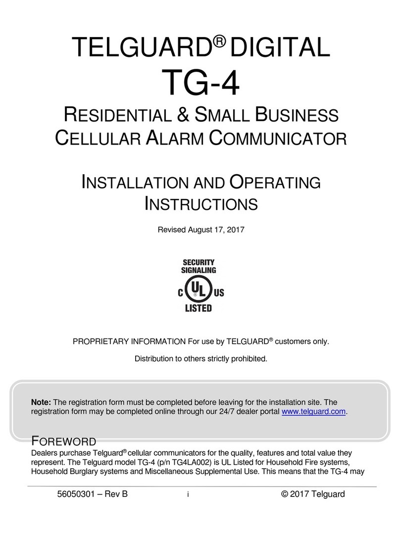
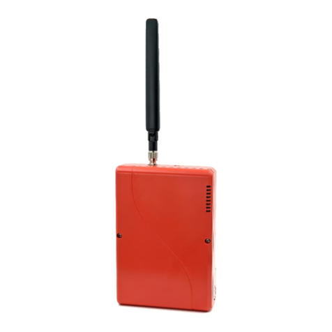
Telguard TG-4 User manual

Telguard

Telguard TG-4 User manual

Telguard TG-4 User manual

Telguard

Telguard TG-4 User manual

Telguard TG-7 Series Installation guide

Telguard

Telguard TG-7 Series Installation guide

Telguard TG-7 Series Installation guide

Telguard

Telguard TG-7 Series Installation guide

Telguard TG-7UBL Installation guide

Telguard

Telguard TG-7UBL Installation guide

Telguard TG-7FP Original operating instructions

Telguard

Telguard TG-7FP Original operating instructions

Telguard TG-7A Installation guide

Telguard

Telguard TG-7A Installation guide

Telguard TG-7FP Original operating instructions

Telguard

Telguard TG-7FP Original operating instructions

Telguard TG-1 Express CDMA User manual

Telguard

Telguard TG-1 Express CDMA User manual

Telguard Tg-5 GSM User manual

Telguard

Telguard Tg-5 GSM User manual

Popular Security System manuals by other brands

Paradox MG5000 user guide

Paradox

Paradox MG5000 user guide

Paradox IP100 instructions

Paradox

Paradox IP100 instructions

Watchguard DVR8E(PACK) Quick installation guide

Watchguard

Watchguard DVR8E(PACK) Quick installation guide

Co2meter CM-1029 installation manual

Co2meter

Co2meter CM-1029 installation manual

Paradox Marine Magel 6130 Instalation manual

Paradox

Paradox Marine Magel 6130 Instalation manual

Electronics Tomorrow BLE Alarm Cube instruction manual

Electronics Tomorrow

Electronics Tomorrow BLE Alarm Cube instruction manual

Co2meter RAD-0102-6 operating instructions

Co2meter

Co2meter RAD-0102-6 operating instructions

Qlight SBE130 instruction manual

Qlight

Qlight SBE130 instruction manual

One Control Tire Linc quick start guide

One Control

One Control Tire Linc quick start guide

Paradox Magellan MG5050 EN Reference & installation manual

Paradox

Paradox Magellan MG5050 EN Reference & installation manual

Alarmcom Water Dragon ADC-SHM-100-A installation guide

Alarmcom

Alarmcom Water Dragon ADC-SHM-100-A installation guide

Burtonsafes Keyguard Combi User instructions

Burtonsafes

Burtonsafes Keyguard Combi User instructions

GSM Activate 2G RF PIR manual

GSM Activate

GSM Activate 2G RF PIR manual

Abus 2510 Fitting and operating instructions

Abus

Abus 2510 Fitting and operating instructions

Watchguard ALC-CAM2 user manual

Watchguard

Watchguard ALC-CAM2 user manual

Verkada BP41 install guide

Verkada

Verkada BP41 install guide

Optex Morse MDC 16 ETX user manual

Optex Morse

Optex Morse MDC 16 ETX user manual

Visonic POWERMAX PRO Installer's guide

Visonic

Visonic POWERMAX PRO Installer's guide

manuals.online logo
manuals.online logoBrands
  • About & Mission
  • Contact us
  • Privacy Policy
  • Terms and Conditions

Copyright 2025 Manuals.Online. All Rights Reserved.