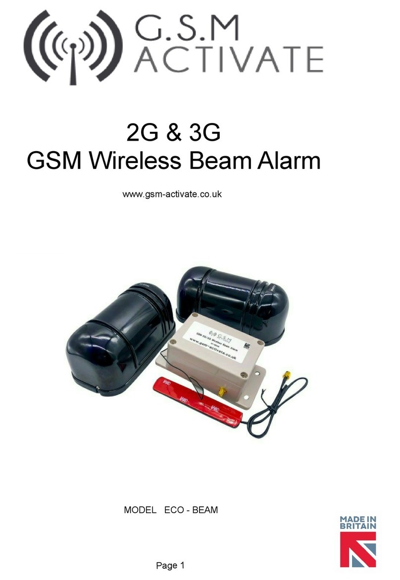
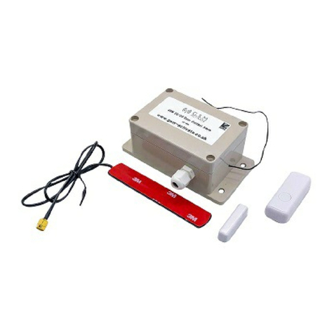
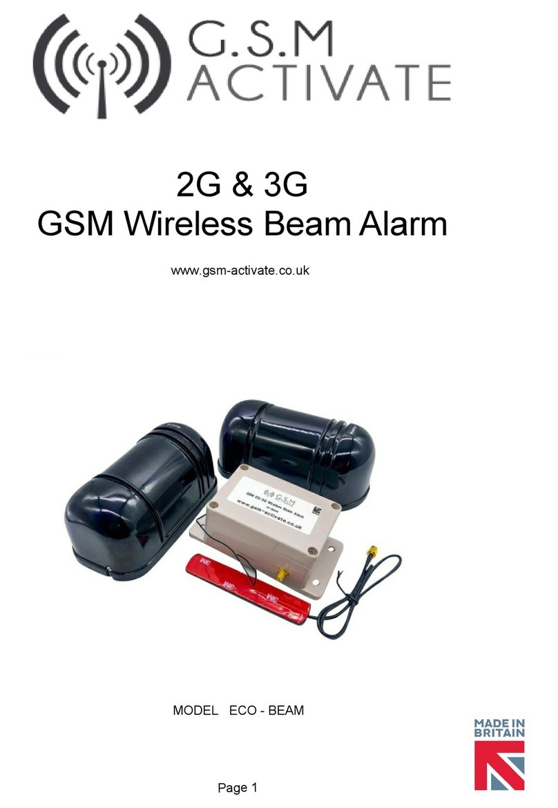
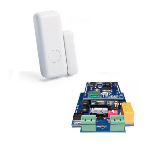
GSM Activate 2G RF PIR User manual

2G & 3G
GSM Portable PIR Alarm
www.gsm-activate.co.uk
MODEL RF - PORTABLE-PIR
PAGE 1

Page 2
Product Information
Our 2G/3G Portable PIR Alarm is a standalone alarm system suitable for indoors or
outside usage. It will alert you using GSM technology by sending a text message and/or
phone call when the Pir sensor (s) are triggered to your mobile phone or landline.
The unit is also enclosed in an IP65 rated box meaning it is perfectly weathered for
outside installation and has passed testing in high temperatures and below freezing
conditions.
GSM Module Specification
● GSM Frequency: Quad band freq 850/900/1800/1900/ 3G Model 2100 Mhz
● Power Supply Voltage: 9 - 24 volts DC - 1 Amp Min
● Current used in standby mode: 60mA Max
● IP65 Rated Enclosure for outside installation
● 2 Amp Relay Output
● Micro 2G or 3G Simcard
● No landline required
● Dimensions - L100 x W68 x H50mm
● Dimensions PCB Only - L95 x W67mm
● Sim Active Function
● Operating Temperature: -10…+40°C
● Programmed by Text/SMS Message
● Text to test signal strength
PIR Specification
● Alert Distance: 8 - 12 metres
● Detection Range is horizontal 110°, vertical 30°.
● PIR size 120 x 70 x 40mm
● Battery Life: 6 - 9 Months
● Wireless Range: 20 metres

Instructions
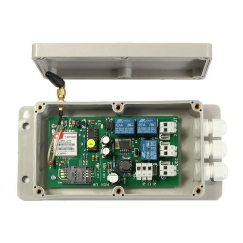
Slide the simcard into the holder making sure that the clipped corner of the simcard lines
up with the clipped corner of the simcard holder as seen in the picture above.
IMPORTANT - PLEASE READ
PLEASE MAKE SURE YOU DISCONNECT THE POWER WHEN YOU FIT THE SIM
CARD THE PLACE THE SIMCARD WITH THE CLIPPED CORNER FACING INWARDS.
PLEASE SEE PICTURE ABOVE
Signal Strength
To help make sure that you have placed the unit in a suitable position you can text the
unit to see how much signal strength the detector is receiving. Simply text the unit
#SIGNAL#
The detector will perform a test on the signal strength.
You will receive a text message telling you the signal strength score between 0 up to 30.
We strongly recommend that you place the unit where you can receive a signal strength
of at least 10.
You will find that a signal strength score of less than 10 the unit will be unreliable.
Page 3

Page 4
How to programme contact numbers
After inserting the simcard into the GSM module, turn the unit on and wait until you see the
GREEN LED is on. This will indicate that you have a mobile signal and the unit is ready for
use.
PLEASE NOTE - To avoid confusion we have colour coded the hash () and the equals ()
symbols.
You will now need to send the text with the contact number (maximum 3 contact numbers)
Example: (HASH) (1,2 or 3) (EQUALS) (phone number) (HASH)
#1=07123456789# Then send this to the simcard number of your unit (with your
preferred mobile number)
#2=07123456789# Then send this as a text to the simcard of the unit (with your
preferred mobile number for second contact)
#3=07123456789# Then send this to the simcard of the unit (with your preferred
mobile number for third contact)
If you wish to cancel a number follow this example
Example: (HASH) (1,2 or 3) (EQUALS) (DELETE) (HASH)
Then send this as a text to the simcard number of your unit.
PLEASE NOTE
Please only send one text message at a time and wait for the GSM detector to send you
back the text acknowledgement NUMBER STORED before you try to add the next number.
Below is a notepad to help you remember the numbers that you have saved to your unit in
the event you need to change, modify or delete them in the future.
#1=_ _ _ _ _ _ _ _ _ _ _ _ _ _ _ _ _ _ _ _ _ _ _ _#
#2=_ _ _ _ _ _ _ _ _ _ _ _ _ _ _ _ _ _ _ _ _ _ _ _#
#3=_ _ _ _ _ _ _ _ _ _ _ _ _ _ _ _ _ _ _ _ _ _ _ _#

Page 5
How to programme the text/SMS message
You can now change the alarm message from “input detected” to one of your choice.
To change the alarm message to one of your choice please send the text command as
follows.
#MESS=YOUR MESSAGE#
The detector will reply with the text message “number stored”
PLEASE NOTE
You can only use a maximum of 19 characters including spaces for your customised
message.
Telephone Call Alerts
The Portable PIR Alarm can be programmed to send you a telephone call after each
text alarm has been has been sent.
You will receive approximately three ring tones.
The unit will then hang up automatically. This is to prevent call charges being incurred.
To set the call alerts to ON please send the text message as follows.
#CALL=ON#
The unit will reply back with the text message “call on”
To disarm call alerts please send the text message as follows
#CALL=OFF#
If the call function has been set to ON you will receive a text message then shortly after a
phone call.

Installation of the PIR Sensor
PLEASE NOTE
The PIR sensor should be installed at a height of 1.8 - 2.2 metres from the ground and its
range is horizontal 110º and vertical 30º .Additionally, the PIR sensor should be within
20 metres of the GSM Detector Module (see fig 1)
1. Find a suitable location for the PIR Sensor and ensure that the sensor is
mounted on a stable structure.
2. When installing the receiver, take care to position the receiver out of direct sunlight as
this will reduce the sensitivity.
3. Ensure the sensors line of sight is free from false alarm sources such as bushes, trees,
etc. Pay attention to these as they may change seasonally.
4. It is important to have the correct power supply to operate this device successfully. You
will need a 12 volt 2 Amp supply or 12 volt battery. You can purchase both of these from
our website www.gsm-activate.co.uk
5. Now you have the transmitter and receiver fitted to the location, you can carry out
alignment. You will now need to power the unit ON.
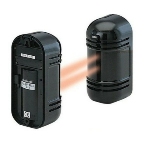
6. Alignment of the infrared beams. There are two adjustments, left and right and up and
down. The photo below should give you an indication of how to do this.
Page 6

Page 7
How to use the 2G/3G Portable PIR Alarm
Once you have positioned the pir sensor, installed the simcard and programmed the
numbers the system is ready to use.
The GSM Portable PIR Alarm has two modes, alarm mode and auto mode. In alarm
mode you have to arm the alarm manually when required. In auto mode, the alarm is
always armed. You can choose the best mode that suits your requirements.
These modes are selected by sending the text message as follows.
#mode=1# Alarm Mode (default)
#mode=2# Auto Mode
Mode 1 - Alarm Mode: #mode=1#
Alarm mode is the default mode. You will need to set the alarm to ON before it detects
movement and sends an alarm message.
To set the alarm to ON you will need to send the text message
#ALARM=ON# This will activate the alarm.
#ALARM=ON# This will deactivate the alarm.
It is important to remember that when the alarm has been triggered you will need to reset
the alarm by sending another text message #ALARM=ON#
Mode 2 - Auto Mode: #mode=2#
The alarm is always armed and will trigger when movement is detected. It will
automatically reset back into armed mode after 20 seconds of no movement being
detected.
How to use the Relay Output
Dipswitch 2 = OFF ref page 3
The Portable PIR Alarm has a 2 amp relay output which can be used to switch on
external electrical devices such as lighting, sirens etc.
By texting the unit you can turn the relay ON or OFF. Below are examples on how to do
this.
#REL=ON# This will turn the relay output ON
#REL=OFF# This will turn the relay output OFF
After each operation the unit will reply with the text message REL ON/OFF
Dipswitch 2 = ON ref page 3
The relay can also be set to pulse for 20 seconds when the inputs have been triggered. To
activate this mode you need to set DIPSWITCH 2 to the ON position. (Page 3)
This can be used to trigger a siren or reset other equipment.

PAGE 8
Installation and Pairing the PIR
Installation of the PIR Sensor
PLEASE NOTE The PIR sensor should be installed at a height of 1.8 - 2.2 metres from the
ground and its range is horizontal 110º and vertical 30º .Additionally, the PIR sensor
should be within 20 metres of the GSM Detector Module (see fig 1)
Pairing the PIR Sensor and GSM Detector
To connect the wireless sensors you will need to go through a process so that the devices
are matched to the receiver on the GSM module.
1. Switch ON the GSM module.
2. Switch on the beams and allow them to warm up for 15 seconds.
3. Hold down the pairing button on the RF Module for 3 seconds (refer to page 1)
4. Trigger the beams by placing your hand enough to block both of the beams.
5. The RF module has a RED LED which will flash when pairing is complete.
6. Dipswitch 1 controls 2G and 3G
7. Dipswitch 2 controls Relay Mode

Page 9
09/072018 AD
Quick Reference
Factory Reset
To reset the unit back to factory settings you will need to send the text message #RESET#
WARNING
By doing this the unit will reset all of your parameters. Only send the reset command when
necessary
The GREEN LED will flash 8 times to indicate that reset is complete.
Dipswitch Settings
Dipswitch 1 - ON = 3G Selected
OFF = 2G Selected
Dipwitch 2 - ON = Pulse Relay (20 Seconds)
OFF = Relay Off
For more technical support please browse the FAQ’s on our website
www.gsm-activate.co.uk
Alternatively email our technical support team at [email protected] and we will
do our best to get back to you within 24 hours Monday to Friday.
This manual suits for next models
1
Table of contents
Other GSM Activate Security System manuals
GSM Activate
GSM Activate GSM PT100 User manual

GSM Activate
GSM Activate ECO-BEAM User manual
GSM Activate
GSM Activate e-CO Series User manual
GSM Activate
GSM Activate AD-SD User manual
GSM Activate
GSM Activate 2G RF BEAM User manual

GSM Activate
GSM Activate ADRV11 User manual

GSM Activate
GSM Activate ECO-BEAM User manual

GSM Activate
GSM Activate Alarm Pro 20 User manual

GSM Activate
GSM Activate 3G RF DOOR User manual

GSM Activate
GSM Activate ECO Series User manual