Telguard TG-4 User manual

TELGUARD®
TG-4 CDMA
RESIDENTIAL & SMALL BUSINESS
CELLULAR ALARM COMMUNICATOR
QUICK INSTALL GUIDE
Revised August 14, 2014
PROPRIETARY INFORMATION For use by TELGUARD®customers only.
Distribution to others strictly prohibited.
Note: The registration form must be completed before leaving for the installation site. There are two ways
to register a Telguard:
Register online at www.TelguardOnline.com (preferred method),
Send the electronic registration form at www.telguard.com

56047201 1© 2014 Telguard
FOREWORD
Dealers purchase Telguard®cellular communicators for the quality, features and the total value they
represent.The Telguardmodel TG-4 (p/n TG4V0004) is UL Listed for Household Fire systems,
Household Burglary systems and Commercial Burglary applications. Thismeans that the TG-4 may
be usedin Household Burglarysystems, Household Fire systems or Commercial Burglarysystems
as the primary or secondary communicationpath.
TELGUARD SUPPORT
Telguard Support for all Telguard products is available Toll Free at 800-229-2326
Option 1 for Registration and Customer Service
Option 5 for Sales
Option 9 for Technical support
Email Support is provided by:
CustomerService@telguard.com: Customer Service and Registration
Returns@telguard.com: RMA requests
Telguard also hosts two sites for public and dealer access:
www.telguard.com: public access site.
www.TelguardOnline.com: dealer-only access.
ABOUT THIS GUIDE
The material and instructions covered have been carefullychecked for accuracy and should provide
enough guidance for a successful installation.
Note: If more detailed information is required, you may download the full version of the
Installation Manual from our websites: www.TelguardOnline.com or www.telguard.com.
TERMS AND CONDITIONS
“Telguard Terms and Conditions of Sale” as well as “Telguard Master Reseller Agreement –
Telguard Services” are applicable. For more information, visit the dealer portal at
www.TelguardOnline.com or contact Customer Service at 800-229-2326, option 1.
REPAIR AND WARRANTY
Repair of Telguard equipment should only be referred to Telguard. Telguardwill repair or replace (our
option) inoperative units for up to two years from date of manufacture.This excludes damage due to
lightning, unauthorized modifications or installer error. Telguard is not responsible for incidental or
consequential damages.
If a Telguard unit needs to be returned for repair, please return the product to the distributor that the
unit was originally purchased from. The distributor will contact Telguard to obtain an RMA based on
the unit’s warranty eligibility. Units returned for repair that are out of the warranty period or do not
meet warranty criteria will be subject to a minimum repair charge.

56047201 2© 2014 Telguard
GENERAL DESCRIPTION
The Telguard TG-4 is a digital cellular transmission device that is installed at the protected
premises to provide alarm transmission for security systems. The Telguard TG-4 CDMA transmits
alarm signals over the nationwide digital cellular network if the telephone line or data network has
been disrupted, compromised or when there is no wire line service available.
FEATURES
OPERATING MODE
The Telguard model TG-4 CDMA is a digital cellular radio alarm transmission device used to
provide a primary or back-up transmission path (cellular) for alarm panels. Depending on the TG-4
CDMA configuration (determined at time of installation), the alarm panel will use the PSTN line or
cellular as primary or back-up (secondary) transmission path to deliver alarm messages. When it
is configured as a backup, it will provide transparent access from the alarm panel to the central
station. When transmitting an alarm signal using the cellular path, the Telguard obtains its data
from the alarm panel by way of a Telco line interface.
AUTOMATIC ALARM FORMAT DETECTION
The default program setting of the Telguard TG-4 CDMA is for Auto Detection of the panel’s alarm
format. Auto Detection allows the Telguard to adapt to receive any listed format. For a complete list
of acceptable formats, refer to the full Installation Manual available at www.TelguardOnline.com.
COMPLETE SUPERVISION OF COMMUNICATION PATH
LINE FAULT CONDITION (LFC)
The Telguard monitors voltage on the incoming Telco line. If an inoperative Telco line is identified, a
Telco line fault condition (LFC) is declared.
NOSERVICE CONDITION (NSC)
Declared when the Telguard is unable toregister with the cellular network or the signal strength
drops below -114 dBm.
RADIO COMMUNICATIONS FAILURE CONDITION (RFC)
Radio communicationsfailure condition (RFC) is declared whenTelguard is unable totransmit over
the cellular network even with acceptable signal strength. RFC is cleared when communication is
restored.
PANEL PRESENCE FAILURE CONDITION (PPFC)
Panel presence failure condition(PPFC) is declared when the Telguard is unable todetect the
presence of the host alarm panel. PPFC is restored immediately after the connection to the panel is
restored and maintained for the delay period.
Note: The factory default for PPFC is Disabled and needs to be Enabled for its use.
CONTROL FAILURE TO COMMUNICATE (CFC)
The Control Failure to Communicate(CFC)feature is an option that allows the Telguard unit to
monitor the number of communication attempts the alarm panel makes over Telco before the
Telguard becomes the main path of communication. Note that the CFC condition causes the
Telguard unit to redirect communications to the cellular channel, but it is not indicated on the STC
LED, nor does it cause either of the externalrelays to be tripped.

56047201 3© 2014 Telguard
NOTE: The factory default for CFC is Disabled and needs to be Enabled for its use.
When the Telguard is configured as a Cellular-Only, the CFC function is not applicable.
STANDARD LINE SECURITY
The Telguard TG-4 CDMA meets the requirements for Standard Line Security (equivalent to
previouslyknown AA Grade security) when used with a UL Listed compatible alarm panel and when
monitored using the 200-second Supervision cellularservice plan.
WARNING: Standard Line Security has only been evaluated between the TG-4 CDMA
and the TCC. It is the responsibility of the installer to verify Standard Line Security from
the Listed control unit to the Listed receiver through the TG-4 CDMAas marked on the
alarm panel and as indicated in the control unit manufacturer's installation instructions.
COMPLETE POWER SUPERVISION
LOW/MISSING BATTERY CONDITION (LBC)
The Telguard checks the backup battery voltage on initial power-up and every 60 seconds thereafter.
If the battery voltage is low or there is an issue with the battery charger a LBC is declared. When the
battery voltage normalizes, the condition is cleared.
AC FAILURE CONDITION (ACFC)
ACFC is detected immediately when the AC power drops below102 VAC. When AC power returns
to normal, the AC Power LED turns on immediately andfull restoral occurs after 60seconds.
Note: If the Telguardis being powered through its DC connection, a Low Power Failure
(LPF) will occur to indicate the DC voltage being used as a main power source is low.
DIAL TONE FAILURE (DTF)
A Dial Tone Failure (DTF) is declared when the 30V supply circuitthat provides dial tone dropsto
20V or less while the alarm panel is on-hook. Contact Technical Support for resolution.
CATASTROPHIC FAILURE (CF)
Catastrophic Failure (CF) is any condition that causes the Telguard to stopfunctioning at all levels,
most commonly because of power failure. If power is connected properly to the unit when a CF
occurs, please contact TelguardTechnical Support for resolution.
COMPLETE FACTORY RESET OPTION
To begin the factory reset, wait for the unit to initialize and hold down the RSSI button for 15 seconds.
After 15 seconds, the LEDs will begin to sequentially turn on and off in a cascading pattern indicating
the factory reset is in progress. After the reset has concluded, the LEDs will go back to normal
(factory default) status and the unit will attempt to re-provision. However, provisioning will only be
successful if the device isalreadyregistered and pending activation.
INSTALLATION
STEP 1: REGISTER THE TELGUARD UNIT
The registration form must be completed before leaving for the job site to install the Telguard
product. The registration form may be completed by:

56047201 4© 2014 Telguard
Online Dealer Portal – www.TelguardOnline.com
Online Form – www.telguard.com
Registrations completed via www.telguardonline.com are automatically entered into the Telguard
database. Registrations submitted on www.telguard.com require manual entry.
Note: During high traffic periods, some cellular network providers may experience a
delay in activation for up to 30 minutes. It is important that you register the Telguard
device prior to leaving for the job site to ensure that it’s fully functional when installed.
STEP 2: LOCATE UNIT AND MEASURE SIGNAL STRENGTH (RSSI)
LOCATE UNIT
Temporarily place the Telguard unit near the alarm panel. Permanent mounting should only be done
after determining the optimum cellularreception location.
CONNECT POWER
Option 1: Backup Battery and AC Power Transformer
A battery can be connected tothe battery connector (labeled BATT) or tothe 3-pin terminal block
(labeled BATT - +). Make sure that the battery is sized appropriately to meet the installation
requirements and that the battery wires are at least ¼ inch apart from the other wiring in the system.
Connect the Telguard AC transformer to AC terminals using stranded copper insulated wire.
Option 2: DC power
To apply DC power to Telguard from a host alarm panel, connect the panel power and ground
connections into the respective DC and GND connections on the TG-4 CDMA. When using this
option, no other power connections (battery or AC) should be wired.
CONNECT ANTENNA AND TEMPORARILY PLACE UNIT
Connect the supplied antenna to the antenna port and press the RSSI button on the side of the unit
to toggle the LEDs between RSSI display and normal mode. For reference on reading the RSSI,
refer toWiring Diagram.
Note: Optimum performance can usually be found at the highest point within a
building with the fewest number of walls between the Telguard’s antenna and the
outside of the premises. Avoid mounting the Telguard’s antenna near other electronic
devices to avoid interference.
STEP 3: VERIFY PANEL ALARMS OVER THE TELCO CONNECTION
Connect alarm panel and Telco line to the Telguard. Plug the modular jack of the alarm panel into
J16 (black jack) of the Telguard and the incoming Telco connection into J17 (gray jack). Trip a
zone on the alarm panel and transmit over the Telco line. This step is important to verify the panel
is programmed with valid account code and central station information before transmitting signals
through the cellular network.
STEP 4: PROGRAM,ACTIVATE &TRANSMIT ALARMS OVER CELLULAR NETWORK
When first powered on, the Telguard will attempt to get provisioned by the CDMA network.

56047201 5© 2014 Telguard
During this process, LED #5 will go into a fast flashing pattern, which could last up to 60 seconds.
Confirm the Telguard has been provisioned by the CDMA network by verifying LED #5 is off. If
instead of turning off, LED #5 begins to slow flash, the provisioning process has failed.
Installation Tip: To reattempt the Cellular provisioning, press and hold the RSSI button
for five seconds until you see the fast flashing pattern on LED #5. If the unit continues
to fail provisioning, call Telguard Technical Support.
After the unit is provisioned by the Cellular network, it will be ready for activation. From the panel,
initiate a signalto be transmitted by the TG-4 CDMA. During the processing of the first alarm signal
the Telguard will transmit all of the necessary parameters to theTelguard Communication Center
(TCC). Upon validation by the TCC, the unit will activate. Once the unit activates it will begin
operating in normal mode; LED #1 will be on solid.
The first alarm is used only to activate the Telguard unit. The first alarm will NOT be transmitted to
the central station. Trip several alarms on the alarm panel and verify that the central station received
them by calling the central station operator.
STEP 5: CONNECT SUPERVISORY TRIP OUTPUTS
The Telguard provides the host alarm panel with two supervisory trip outputs for reporting a Telguard
system trouble code to the central station. The supervisory trip outputs are programmable remotely
via the www.TelguardOnline.com site or locallywith a butt-set. The programming options for these
supervisory trip outputs can beany combination of ACFC, LBC, LFC, NSC, RFC, and DTF.
NOTE: UL Listed installation of the TG-4 CDMA will at a minimum have a trip output
connected to the alarm panel to indicate low A/C (ACFC) and low battery (LBC).
CHECK PROPER OPERATION OF TELGUARD SUPERVISORY OUTPUT
Check for proper operation of each programmed supervisory output by causing it to trip the alarm
panel and making sure the proper LED illuminates. Skip the testing of any supervisoryfunctionsthat
have not been enabled. If necessary, reprogram the alarm panel to send proper alarm code when
tripped by the Telguard’s supervisory output.
STEP 6: CONNECT AND TEST THE TRIP INPUT (OPTIONAL)
In addition to the interface to the alarm panel, a single trip input may be connected to the terminal
block of the TG-4 CDMA. When the input is tripped, a supervisory message is sent to the central
station via the Telguard Communications Center. The functionality of the Trip input can be
customized via the www.telguardonline.com site or by a Telguard Customer Service
representative.
UL Note: Trip input is not evaluated when connected to Burglary Zones on the panel.
For UL installations, burglary zones shall not be connected to the Trip Input.
STEP 7: COMPLETE THE TELGUARD INSTALLATION
The last step is to permanently mount the Telguard.
1. Attach earth ground to thegrounding screw located on lower right-hand corner of printed
circuit board assembly and permanently mountthe Telguard enclosure.
2. Install center-mounting screw (not supplied) and slide the enclosure onto this screw.
3. Install two screws in the bottom mounting holes to secure the TG to the wall.

56047201 6© 2014 Telguard
TELGUARD INTERACTIVE
The Telguard Interactive feature is an added service that provides the flexibility of remote
arming/disarming of the panel and end-user notification of events. If enabled, the wiring and
programming of the panel will vary from a standard Telguard installation. To ensure a successful
installation, four steps must be taken:
1. Enable the Telguard Interactive feature from www.TelguardOnline.com
2. Program and wire the panel in accordance to the requirement guidelines provided.
Note: Visit www.telguard.com or www.TelguardOnline.com for downloadable wiring and
programming instructions customized for the most widely used panels.
3. Use the dealer portal to verify that all interactive features are fully functional
Telguard Interactive service can work with any single-partition security system provided that the
alarm panel can be programmed with the following:
Alarm reporting format must be programmed to Contact ID.
A programmable output must be configured to immediately switch to ground when the
system is armed and return to open state when disarmed.
An available zone must be programmed as a Momentary Keyswitch, so that a temporary
short will cause the panel to switch states (from Armed to Disarmed and vice versa).
Opening and Closing reports must be enabled to report at all times.
Note: Telguard Interactive will repurpose the STC2 and Trip Input connections and
change the Operating mode of the TG-4 CDMA to Cellular-Only.
UL Note: UL has not evaluated the Telguard Interactive feature. This feature cannot be
used in UL Listed Installations.
TROUBLESHOOTING QUICK REFERENCE TABLE
Telguard Event LED Indication Relay
Output Radio Message Internal Action
STC
Telguard
System
Trouble
Conditions
ACFC /
LPF AC LED off. STC
LED 2 flashes
continuously 1 time.
Optional None If main power source is AC, switch to standby
battery if present, monitor battery,monitor AC
for restoral. If main power source is DC, wait
for voltage to return to normal level.
LBC STC LED 2 flashes
cont. 2 times.Optional None Wait for LBC restoral, charge battery.
LFC STC LED 2 flashes
cont. 3 times.Optional None Transmit alarm via radio if necessary. When
Telco is restored, remove LFC condition.
NSC STC LED 2 flashes
cont. 4 times. Optional None Continue to validate signal strength, NSC will
restore when signal returns
RFC STC LED 2 flashes
cont. 5 times.Optional None Wait for RFC restoral.
DTF
Dial Tone
Failure
STC LED 2 flashes
cont. 6 times.Yes Yes Internal 30V supply circuit failure. Return unit
for repair on RMA.
PPF STC LED 2 flashes
cont. 7 times No Yes Wait for PPF restoral.
Not Activated Activation LED 1 off Yes None Telguard will not function until unit is
activated.

56047201 7© 2014 Telguard
Activation Failed LED 1 and 4flashing No None Press RSSI button twice to clear fault.
CDMA Network
provisioning failed LED 5 flashing slowly No None Press and hold RSSI button for 5 seconds to
restart provisioning.
Automatic Self-Test Radio LED 5 flashes
on transmit None Yes
(Self-test) Send Self-test information to central station
via TCC, return to ready state
Telguard Remote Query
– Activated by
Customer Service.
Radio LED 5 flashes
on transmit None Yes
(Status data) Send Status data to TCC for review by
customer service
Telguard Enable and
Configuration Upload – Radio LED 5 flashes
on transmit None Yes
(Setup data) Telguard sends setup configuration to TCC
and switches to READY to begin operation.
Disable TX –
Communication Center
initiated.
Radio LED 5 flashes
on transmit Yes Yes
(Status data) TX capability is disabled until further notice.
Telguard can still receive radio signals from
TCC.
Note: If several trouble conditions are present, the STC LED will flash all of the indications
in sequence.
WIRING DIAGRAM
T
R
12 3 5 6 1 2
1
2
3
4
5
6
7
8
Power LED
EARTH
GROUND
RSSIMode Button
System Status
LEDs
Alarm Panel
Battery
Connector
Acceptable RSSI Range
BATTERY
Battery wire should be at
least ¼ inch apart from
AC wires
1 2 1 32
4
12 123456 1 21 2 3
AC
+
-
OPTIONAL
BATTERY
STC2
(N.C) STC1
(N.O.) GND IN
TRIP
2
34 5 6
7
GREEN
R
8
1
T
RED
INCOMING
TELCO
RJ31X
TELGUARD
TG-4 CDMA
GND DC
1 FLASH= ACFC LOW/MISSING AC
LPF LOW DC INPUT
2 FLASH = LBC LOW BATTERY
3 FLASH = LFCLINEFAULT
4 FLASH= NSC NO SERVICE
5 FLASH = RFC RADIO FAILURE
6 FLASH = DTF DIALTONE FAIL
7 FLASH = PPF PNL PRES FAIL
LED 1
OFF NOT ACTIVATED
ACTIVATEDON
System StatusLEDs (Normal Mode)
ACTIVATION DENIED (DISABLED)FLASHING
ACTIVATION
LED 2
OFF
FLASHING
SYSTEM
TROUBLE
NO TROUBLE
TROUBLE:
LED 3
OFF
ON
PANEL COMM PANELON-HOOK (PRIMARY)
PANELON-HOOK (BACKUP)
LED 4
OFF IDLE
WAITING FOR RESPONSE FROMTCCON
ACTIVATION DENIEDFLASHING
TMC COMM
LED 5
OFF IDLE, PROVISIONED BYCDMA NETWORK
RADIO INITIALIZINGON
CDMA PROVISIONING IN PROGRESSFAST FLASH
RADIO STATUS
PANELOFF-HOOKFLASHING
LED 6
LED 7LED 8
OFF NOT USED
OFF NOT USED
NOT USED
NOT USED
ACNOT CONNECTED
UNIT MAY BE RECEIVING
POWER FROM DC/BATTERY
OFF
POWER LED
FLASHING STANDARDLINESECURITY ENABLED
(2 FLASHES EVERY 5 SECONDS)
AC
(12V 800MA)
ACCONNECTED TOUNITON
CDMA PROVISIONING IS REQUIREDSLOW FLASH
RADIO IS SENDING MESSAGELONG FLASH
4
LEDs 2-5
Signal (dBm) NO
SVC < -110 > -110 > -100 > -90 > -80 > -70 > -60
RSSI (bars) NONE 1½1 2 2½ 3 3½
System StatusLEDs (RSSI Mode)
OFF
BLINKING
ON
Other manuals for TG-4
3
Table of contents
Other Telguard Security System manuals
Telguard
Telguard TG-7FP Original operating instructions
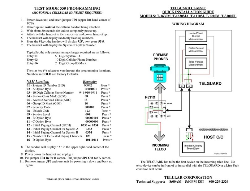
Telguard
Telguard T-1630M Classic User manual
Telguard
Telguard TG-7 Series Installation guide

Telguard
Telguard TG-7FP Original operating instructions

Telguard
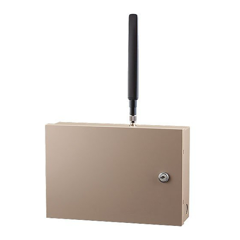
Telguard TG-7 Series Installation guide
Telguard
Telguard TG-7A Installation guide
Telguard
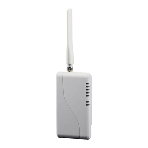
Telguard TG-1 Express CDMA User manual
Telguard
Telguard TG-4 User manual

Telguard
Telguard Tg-5 GSM User manual
Telguard
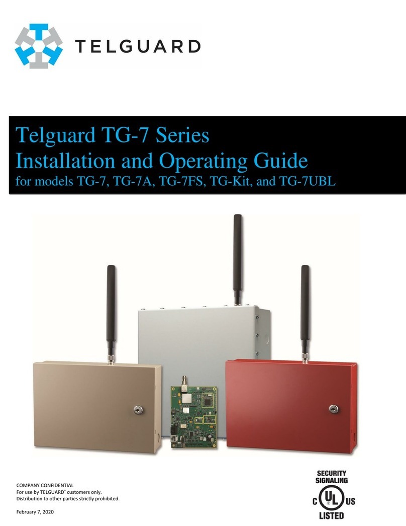
Telguard TG-7UBL Installation guide
