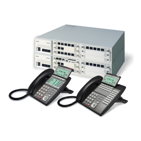
NEC Xen Topaz User guide

System Hardware Manual
NEC Business Solutions Ltd.
Document No.:8846
Release 1.1
September, 2004
Xen Topaz

September 2004 NEC Business Solutions Ltd
ii System Hardware Manual
Doc. No. 8846 - Release 1.0
September 2004
THIS PAGE INTENTIONALLY LEFT BLANK

System Hardware Manual i
Doc. No.: 8846 - Release 1.1
September 2004
Table of Contents
Chapter 1 Regulatory Information
Section 1 Electromagnetic Interference (EMI). . . . . . . . . . . . . . . . . . . . . . . . . . 1
Section 2 Incidence of Harm. . . . . . . . . . . . . . . . . . . . . . . . . . . . . . . . . . . . . . . . 1
Section 3 Hearing Aid Compatibility . . . . . . . . . . . . . . . . . . . . . . . . . . . . . . . . . 1
Section 4 Service Requirements . . . . . . . . . . . . . . . . . . . . . . . . . . . . . . . . . . . . 1
Section 5 Compliance Information . . . . . . . . . . . . . . . . . . . . . . . . . . . . . . . . . . . 2
Section 6 Connection Requirements for Earthing the Topaz KSU . . . . . . . . . 2
Section 7 Voice Announcement/Monitoring . . . . . . . . . . . . . . . . . . . . . . . . . . . 2
Section 8 Music on Hold . . . . . . . . . . . . . . . . . . . . . . . . . . . . . . . . . . . . . . . . . . . 3
Section 9 Battery Disposal and Safety. . . . . . . . . . . . . . . . . . . . . . . . . . . . . . . . 3
Chapter 2 About This Manual
Section 1 Symbols in this Manual . . . . . . . . . . . . . . . . . . . . . . . . . . . . . . . . . . . 5
Chapter 3 The Components
Section 1 List of components . . . . . . . . . . . . . . . . . . . . . . . . . . . . . . . . . . . . . . 7
Section 2 KSUs. . . . . . . . . . . . . . . . . . . . . . . . . . . . . . . . . . . . . . . . . . . . . . . . . . . 8
924M KSU. . . . . . . . . . . . . . . . . . . . . . . . . . . . . . . . . . . . . . . . . . . . . . . 8
Section 3 System Options. . . . . . . . . . . . . . . . . . . . . . . . . . . . . . . . . . . . . . . . . . 9
OPBOX . . . . . . . . . . . . . . . . . . . . . . . . . . . . . . . . . . . . . . . . . . . . . . . . . 9
32i/NX7E Battery Box . . . . . . . . . . . . . . . . . . . . . . . . . . . . . . . . . . . . . . 9
ABB CARD SET . . . . . . . . . . . . . . . . . . . . . . . . . . . . . . . . . . . . . . . . . 10
Section 4 System Expansion Interface Cards . . . . . . . . . . . . . . . . . . . . . . . . . 10
308E-A1 . . . . . . . . . . . . . . . . . . . . . . . . . . . . . . . . . . . . . . . . . . . . . . . 10
008E-A1 . . . . . . . . . . . . . . . . . . . . . . . . . . . . . . . . . . . . . . . . . . . . . . . 10
Section 5 Optional Interface Cards (Installed into the KSU) . . . . . . . . . . . . . 11
EXIFU-A1 . . . . . . . . . . . . . . . . . . . . . . . . . . . . . . . . . . . . . . . . . . . . . . 11
2PGDU-A1 . . . . . . . . . . . . . . . . . . . . . . . . . . . . . . . . . . . . . . . . . . . . . 12
DSPDB-A1 . . . . . . . . . . . . . . . . . . . . . . . . . . . . . . . . . . . . . . . . . . . . . 12
CF-B1 . . . . . . . . . . . . . . . . . . . . . . . . . . . . . . . . . . . . . . . . . . . . . . . . . 13
Section 6 Optional Interface Cards (installed into OPBOX). . . . . . . . . . . . . . 13

September 2004 NEC Business Solutions Ltd
ii Table of Contents
Doc. No.: 8846 - Release 1.1
September 2004
2/4BRIU-S1 . . . . . . . . . . . . . . . . . . . . . . . . . . . . . . . . . . . . . . . . . . . . . 13
Section 7 Key Telephones . . . . . . . . . . . . . . . . . . . . . . . . . . . . . . . . . . . . . . . . . 14
12TXD TEL . . . . . . . . . . . . . . . . . . . . . . . . . . . . . . . . . . . . . . . . . . . . . 14
Section 8 Optional Terminals . . . . . . . . . . . . . . . . . . . . . . . . . . . . . . . . . . . . . . 18
64BD DSS Console . . . . . . . . . . . . . . . . . . . . . . . . . . . . . . . . . . . . . . . 18
DP-D-1D DOORPHONE . . . . . . . . . . . . . . . . . . . . . . . . . . . . . . . . . . . 19
Chapter 4 Installing the Main KSU
Section 1 Before Installing the KSUs . . . . . . . . . . . . . . . . . . . . . . . . . . . . . . . . 21
General Precautions . . . . . . . . . . . . . . . . . . . . . . . . . . . . . . . . . . . . . . 21
Unpacking . . . . . . . . . . . . . . . . . . . . . . . . . . . . . . . . . . . . . . . . . . . . . . 21
Preparations . . . . . . . . . . . . . . . . . . . . . . . . . . . . . . . . . . . . . . . . . . . . 21
Site Requirements . . . . . . . . . . . . . . . . . . . . . . . . . . . . . . . . . . . . . . . . 21
Environmental Requirements . . . . . . . . . . . . . . . . . . . . . . . . . . . . . . . 21
Section 2 Installing the KSUs . . . . . . . . . . . . . . . . . . . . . . . . . . . . . . . . . . . . . . 22
KSU/OPBOX Size . . . . . . . . . . . . . . . . . . . . . . . . . . . . . . . . . . . . . . . . 22
Secure the KSU to the Wall . . . . . . . . . . . . . . . . . . . . . . . . . . . . . . . . . 23
Wall-wounting the Main KSU . . . . . . . . . . . . . . . . . . . . . . . . . . . . . . . . 23
Section 3 Grounding & ACD Cabling . . . . . . . . . . . . . . . . . . . . . . . . . . . . . . . . 25
Grounding the KSU . . . . . . . . . . . . . . . . . . . . . . . . . . . . . . . . . . . . . . . 25
AC Power Cord . . . . . . . . . . . . . . . . . . . . . . . . . . . . . . . . . . . . . . . . . . 26
Chapter 5 Trunk/Extension Cabling and Installing the Expansion PCBs
Section 1 Trunk Extension Cabling . . . . . . . . . . . . . . . . . . . . . . . . . . . . . . . . . 27
General . . . . . . . . . . . . . . . . . . . . . . . . . . . . . . . . . . . . . . . . . . . . . . . . 27
Precautions for Cabling . . . . . . . . . . . . . . . . . . . . . . . . . . . . . . . . . . . . 27
Trunk Cabling . . . . . . . . . . . . . . . . . . . . . . . . . . . . . . . . . . . . . . . . . . . 27
Extension Cabling . . . . . . . . . . . . . . . . . . . . . . . . . . . . . . . . . . . . . . . . 28
Cable Routing and Clamping. . . . . . . . . . . . . . . . . . . . . . . . . . . . . . . . 29
Section 2 Installing the Expansion PCBs. . . . . . . . . . . . . . . . . . . . . . . . . . . . . 29
General . . . . . . . . . . . . . . . . . . . . . . . . . . . . . . . . . . . . . . . . . . . . . . . . 29
Unpacking . . . . . . . . . . . . . . . . . . . . . . . . . . . . . . . . . . . . . . . . . . . . . . 30
Installing the 308E/008E PCB . . . . . . . . . . . . . . . . . . . . . . . . . . . . . . . 30
Use a blunt object to remove the plastic filler piece for 308E/008E
connectors. . . . . . . . . . . . . . . . . . . . . . . . . . . . . . . . . . . . . . . . . . . . . . 33
Section 3 Power Failure Transfer . . . . . . . . . . . . . . . . . . . . . . . . . . . . . . . . . . . 34
General . . . . . . . . . . . . . . . . . . . . . . . . . . . . . . . . . . . . . . . . . . . . . . . . 34
Power Failure Setting . . . . . . . . . . . . . . . . . . . . . . . . . . . . . . . . . . . . . 34

System Hardware Manual iii
Doc. No.: 8846 - Release 1.1
September 2004
Xen IPK System Hardware Manual
Chapter 6 Key Telephone & Console Installations
Section 1 Key Telephones. . . . . . . . . . . . . . . . . . . . . . . . . . . . . . . . . . . . . . . . . 35
Locations of Controls . . . . . . . . . . . . . . . . . . . . . . . . . . . . . . . . . . . . 35
Key Telephone Legs Adjustment . . . . . . . . . . . . . . . . . . . . . . . . . . . . 36
Key Telephone Wall Mounting . . . . . . . . . . . . . . . . . . . . . . . . . . . . . . 37
Section 2 DLS Console . . . . . . . . . . . . . . . . . . . . . . . . . . . . . . . . . . . . . . . . . . . 40
General . . . . . . . . . . . . . . . . . . . . . . . . . . . . . . . . . . . . . . . . . . . . . . . . 40
Installing the DLS Console . . . . . . . . . . . . . . . . . . . . . . . . . . . . . . . . . 40
Section 3 DSS Console . . . . . . . . . . . . . . . . . . . . . . . . . . . . . . . . . . . . . . . . . . . 42
Chapter 7 Installing the Optional
Equipment
Section 1 SMDR (Station Message Detail Recording) . . . . . . . . . . . . . . . . . . 43
General . . . . . . . . . . . . . . . . . . . . . . . . . . . . . . . . . . . . . . . . . . . . . . . . 43
Unpacking (EXIFU) . . . . . . . . . . . . . . . . . . . . . . . . . . . . . . . . . . . . . . . 43
Switches and Connector Locations. . . . . . . . . . . . . . . . . . . . . . . . . . . 43
Installing the EXIFU PCB . . . . . . . . . . . . . . . . . . . . . . . . . . . . . . . . . . 45
Connecting the SMDR Device (Serial Port) . . . . . . . . . . . . . . . . . . . . 46
Serial Cable Specification . . . . . . . . . . . . . . . . . . . . . . . . . . . . . . . . . . 47
Connecting a Modem . . . . . . . . . . . . . . . . . . . . . . . . . . . . . . . . . . . . . 48
Connecting the PC/LAN . . . . . . . . . . . . . . . . . . . . . . . . . . . . . . . . . . . 48
Section 2 Doorphone/External Paging/External MOH/BGM. . . . . . . . . . . . . . 50
General . . . . . . . . . . . . . . . . . . . . . . . . . . . . . . . . . . . . . . . . . . . . . . . . 50
Unpacking (2PGDU) . . . . . . . . . . . . . . . . . . . . . . . . . . . . . . . . . . . . . . 50
Switches and Connector Locations . . . . . . . . . . . . . . . . . . . . . . . . . . 51
Installing the 2PGDU PCB . . . . . . . . . . . . . . . . . . . . . . . . . . . . . . . . . 51
Installing the Doorphone Boxes . . . . . . . . . . . . . . . . . . . . . . . . . . . . . 52
Installing the Door Unlock Devices . . . . . . . . . . . . . . . . . . . . . . . . . . . 54
Installing the External Paging Speaker/ExMOH/BGM Sources . . . . 55
Section 3 VRS (Voice Response System) . . . . . . . . . . . . . . . . . . . . . . . . . . . . 55
General . . . . . . . . . . . . . . . . . . . . . . . . . . . . . . . . . . . . . . . . . . . . . . . . 55
Unpacking (DSPDB-A1) . . . . . . . . . . . . . . . . . . . . . . . . . . . . . . . . . . . 56
Switches and Connector Locations . . . . . . . . . . . . . . . . . . . . . . . . . . 56
Installing the DSPDB-A1 PCB. . . . . . . . . . . . . . . . . . . . . . . . . . . . . . . 56
Installing the CF-B1. . . . . . . . . . . . . . . . . . . . . . . . . . . . . . . . . . . . . . . 57
Section 4 External Backup Battery. . . . . . . . . . . . . . . . . . . . . . . . . . . . . . . . . . 58
General . . . . . . . . . . . . . . . . . . . . . . . . . . . . . . . . . . . . . . . . . . . . . . . . 58
Unpacking (Battery Box) . . . . . . . . . . . . . . . . . . . . . . . . . . . . . . . . . . . 58
Battery Specifications . . . . . . . . . . . . . . . . . . . . . . . . . . . . . . . . . . . . . 58
September 2004 NEC Business Solutions Ltd
iv Table of Contents
Doc. No.: 8846 - Release 1.1
September 2004
Installing the Backup Battery . . . . . . . . . . . . . . . . . . . . . . . . . . . . . . . . 59
Chapter 8 Installing the Optional
Facilities
Section 1 Installing the Optional BOX . . . . . . . . . . . . . . . . . . . . . . . . . . . . . . . 61
General . . . . . . . . . . . . . . . . . . . . . . . . . . . . . . . . . . . . . . . . . . . . . . . . 61
Unpacking . . . . . . . . . . . . . . . . . . . . . . . . . . . . . . . . . . . . . . . . . . . . . . 61
Installing the OPBOX. . . . . . . . . . . . . . . . . . . . . . . . . . . . . . . . . . . . . . 61
Installing the Optional PCBs to the OPBOX . . . . . . . . . . . . . . . . . . . . 63
Section 2 ISDN BRI (Basic Rate Interface) . . . . . . . . . . . . . . . . . . . . . . . . . . . . 64
General . . . . . . . . . . . . . . . . . . . . . . . . . . . . . . . . . . . . . . . . . . . . . . . . 64
Unpacking . . . . . . . . . . . . . . . . . . . . . . . . . . . . . . . . . . . . . . . . . . . . . . 64
Switches and Connector Locations . . . . . . . . . . . . . . . . . . . . . . . . . . 65
LED Indicators . . . . . . . . . . . . . . . . . . . . . . . . . . . . . . . . . . . . . . . . . . . 67
Chapter 9 System Start Up
Section 1 System Start Up . . . . . . . . . . . . . . . . . . . . . . . . . . . . . . . . . . . . . . . . . 69
Before Starting Up the System . . . . . . . . . . . . . . . . . . . . . . . . . . . . . . 69
Powering Up the System . . . . . . . . . . . . . . . . . . . . . . . . . . . . . . . . . . . 69
Section 2 Programming Mode . . . . . . . . . . . . . . . . . . . . . . . . . . . . . . . . . . . . . . 71
Enter the Programming Mode . . . . . . . . . . . . . . . . . . . . . . . . . . . . . . . 71
Exit Programming Mode . . . . . . . . . . . . . . . . . . . . . . . . . . . . . . . . . . . 71
Save (Backup) the Customer Data . . . . . . . . . . . . . . . . . . . . . . . . . . . 72
Load the Customer Data . . . . . . . . . . . . . . . . . . . . . . . . . . . . . . . . . . . 74
Section 3 System Shutdown . . . . . . . . . . . . . . . . . . . . . . . . . . . . . . . . . . . . . . . 75
Powering OFF the System. . . . . . . . . . . . . . . . . . . . . . . . . . . . . . . . . . 75
Resetting the System. . . . . . . . . . . . . . . . . . . . . . . . . . . . . . . . . . . . . . 75
Chapter 10 Maintenance
Section 1 Lithium Battery Replacement . . . . . . . . . . . . . . . . . . . . . . . . . . . . . . 77
General . . . . . . . . . . . . . . . . . . . . . . . . . . . . . . . . . . . . . . . . . . . . . . . . 77
Lithium Battery Specification . . . . . . . . . . . . . . . . . . . . . . . . . . . . . . . . 77
Replacing the Lithium Battery . . . . . . . . . . . . . . . . . . . . . . . . . . . . . . . 77
Section 2 Main Software Upgrading . . . . . . . . . . . . . . . . . . . . . . . . . . . . . . . . . 79
General . . . . . . . . . . . . . . . . . . . . . . . . . . . . . . . . . . . . . . . . . . . . . . . . 79
Before Upgrading the Main Software. . . . . . . . . . . . . . . . . . . . . . . . . . 79
Main Software Version Confirmation . . . . . . . . . . . . . . . . . . . . . . . . . . 79
Upgrading the Main Software . . . . . . . . . . . . . . . . . . . . . . . . . . . . . . . 80

System Hardware Manual Disclaimer - i
Doc. No. 8846 - Release 1.1
September 2004
Disclaimer
NEC shall not be liable for any direct, indirect, consequential or incidental
damages about the use of this equipment, manual or any related materials.
The information in this technical manual is advisory in nature and is subject to
change. NEC may make improvements and changes in the products described
in this manual without notice.
Changes will be periodically made to the information in the new editions. Efforts
have been made to ensure that the contents of this manual are correct. Should
you find any error, NEC welcomes your comments to improve our
communications. Please contact NEC on 1800 036 136.
Contents of this manual are subject to change without prior notice at the
discretion of NEC Business Solutions Ltd.
This document has been prepared for the use of employees and customers of
NEC Business Solutions Ltd and may not be reproduced without prior written
approval of NEC Business Solutions Ltd.
Copyright © 2004
NEC Business Solutions Ltd
633 - 647 Springvale Road
Mulgrave Vic 3170

September 2004 NEC Business Solutions Ltd
xx - Disclaimer System Hardware Manual
Doc. No. 8846 - Release 1.1
September 2004
THIS PAGE INTENTIONALLY LEFT BLANK

System Hardware Manual Chapter 1 - 1
Doc. No. 8846 - Release 1.1
September 2004
Regulatory Information Chapter 1
S
ECTION
1
ELECTROMAGNETIC
INTERFERENCE (EMI)
WARNING
This is a Class A product. In a domestic environment this product may
cause radio interference in which case the user may be required to take
adequate measures.
S
ECTION
2
INCIDENCE OF HARM
If the System is malfunctioning, it may also be causing harm to the
telephone network. The Telephone system should be disconnected until
the source of the problem can be determined and until repair has been
made. If this is not done, the Network Provider may temporarily disconnect
the service.
S
ECTION
3
HEARING AID
COMPATIBILITY
The NEC Multiline Terminals that are provided for this system are hearing
aid compatible. The manufacturer of Single Line Telephones for use with
the system must provide notice of hearing aid compatibility to comply with
ACA Technical Standards.
S
ECTION
4
SERVICE
REQUIREMENTS
WARNING
This equipment must only be installed and maintained by service personnel.
In the event of equipment malfunction, all repairs must be performed by an
authorised dealer of NEC Business Solutions Ltd or by NEC Business
Solutions Ltd. It is the responsibility of users requiring service to report the
need for service to one of NEC Business Solutions Ltd authorised agents or
to NEC Business Solutions Ltd.

September 2004 NEC Business Solutions Ltd
2 - Chapter 1 Regulatory Information
Doc. No. 8846 - Release 1.1
September 2004
S
ECTION
5
COMPLIANCE
INFORMATION
This equipment has been tested to comply with all relevant ACA Technical
Standards.
The Xen Topaz KSU must be permanently connected to protective earth, via
the earth terminal inside the KSU.
S
ECTION
6
CONNECTION
REQUIREMENTS FOR
EARTHING THE TOPAZ
KSU
Because this Topaz KSU has been ACA approved as an Earthed-SELV
Customer Switching System for connection to a telecommunications
network, the KSU Earth terminal (on the 308M System Mainboard) MUST
be permanently connected to Earth by connecting a minimum of 2.5mm2
green/yellow conductor cable.
This cable MUST be connected between a Multiple Earth Neutral (MEN)
Bonding Bar at the nearest convenient mains Switch Board to the KSU. This
cable must serve no other purpose than installing the KSU.
CAUTION: If this cable is not installed or requires disconnection, then the
telecommunication network connection(s), namely CO and/or ISDN, must
be disconnected first from the KSU.
Liability for this installation rests solely with the licensed installer/dealer. It is
recommended that the installer provide their label and it is to be placed in
the Main Switch Board, certifying that the installation complies with the
safety earthing installation manual instructions for the Topaz KSU Section
3.1.
(Technical References: AS/NZS 60950:2000, ACIF S009:2001. See
Protective Earthing Conductor requirements.)
S
ECTION
7
VOICE
ANNOUNCEMENT/
MONITORING
CAUTION
The use of monitoring, recording or listening devices to eavesdrop, monitor,
retrieve or record telephone conversations or other sound activities,
whether or not contemporaneous with its transmission may be illegal in
certain circumstances under federal or state laws. Legal advise should be
sought prior to implementing any practice that monitors or records any
telephone conversation. The telecommunications (Interception) Act 1979
(Cth), The telecommunications Act 1997, The Privacy Act 1988 and State
and Territory Listening Devices Legislation are all relevant. Some federal
and state laws require some form of notification to all parties to the
telephone conversation, such as using a beep tone or other notification
methods, or require the consent of all parties to the telephone conversation,
prior to monitoring or recording a telephone conversation. Some of these
laws incorporate strict penalties. Section 6 of the Industry Guidelines
recommend pre-recorded messages or verbal notification to alert callers

Xen Topaz System Hardware Manual
Regulatory Information Chapter 1 - 3
Doc. No. 8846 - Release 1.1
September 2004
that the calls may be monitored:
For example: “Your call may be listened to and recorded for quality and
coaching purposes. Please tell the consultant if you don’t want this to
happen.”
Section 6 of the Industry Guidelines also make recommendations in relation
to notifications in writing.
S
ECTION
8
MUSIC ON HOLD
IMPORTANT NOTE
In accordance with Australian Copyright Law, a license may be required
from The Australian Performing Right Association Limited (APRA), or other
similar organisation, when radio or TV broadcasts are transmitted through
the Music On Hold feature of this telecommunication system. NEC
Business Solutions Ltd hereby disclaims any liability arising out of the
failure to obtain such a license.
S
ECTION
9
BATTERY DISPOSAL
AND SAFETY
This system includes the batteries listed below. When disposing of these
batteries, KSUs and/or cards, you must comply with applicable Federal and
State regulations regarding proper disposal procedures.
IMPORTANT SAFEGUARDS FOR BATTERY DISPOSAL
The incineration, landfilling or mixing of nickel-cadmium or sealed lead
batteries with the municipal solid waste stream is PROHIBITED BY LAW in
most areas. Contact your local solid waste management officials for other
information regarding the environmentally sound collection, recycling and
disposal of the battery.
Nickel-Cadmium or sealed lead batteries must be returned to a Federal or
State approved nickel-cadmium or sealed lead battery recycler. This may be
where the batteries were originally sold or a local seller of automotive
batteries. Contact your local waste management officials for other
information regarding the environmentally sound collection, recycling and
disposal of the battery contained in this product.
Table 1-1: Battery Types and Quantities
Unit Name Type of Battery Quantity
IP2AT-924M KSU Lithium 1
DX2E-32i/NXE Battery Box Lead Acid
(User supplied)
2/4

September 2004 NEC Business Solutions Ltd
4 - Chapter 1 Regulatory Information
Doc. No. 8846 - Release 1.1
September 2004
CAUTION
Danger of explosion if batteries are incorrectly installed. Replace only with
the same or equivalant type of battery as indicated throughout this manual.

System Hardware Manual Chapter 2 - 5
Doc. No. 8846 - Release 1.1
September 2004
About This Manual Chapter 2
S
ECTION
1
SYMBOLS IN THIS
MANUAL
The meaning of each Symbol used in this manual is illustrated below.
CAUTION
The system does NOT support the Power-On Maintenance.
DO NOT POWER ON until all installations have been completed.
Symbol Description
This symbol informs you about additional notes.
This symbol alerts you to important information.
This symbol recommends you to refer the related parts.

September 2004 NEC Business Solutions Ltd
6 - Chapter 2 About This Manual
Doc. No. 8846 - Release 1.1
September 2004
THIS PAGE INTENTIONALLY LEFT BLANK

System Hardware Manual - 7
Doc. No. 8846 - Release 1.1
September 2004
The Components Chapter 3
S
ECTION
1
LIST OF COMPONENTS
Item Description QTY Note
IP2AT-924M KSU Main KSU 1 Initially equipped :
-CPU with Main Software
-Power Supply (110V/240V)
-External Backup Battery Charger
-SLT Ringer
-3 Trunks + 8 Hybrid Ext. I/F
- 1 MOH/BGM Music Input
- 1 External Paging Input
-1 Power Failure Transfer Circuit
-2 mounting spaces for 308E/008E
-1 slot for 2PGDU
-1 slot for EXIFU
-1 connector for DSPDB
IP2WW-OPBOX Additional Box for Optional
I/F Cards
1 Joint to 924M KSU.
2 slots for Optional I/F Cards.
IP2AT-308E-A1 3 Trunks + 8 Hybrid
Extensions I/F
2 Installed into 924M KSU.
1 Power Failure Transfer Circuit
is provided.
IP2WW-EXIFU-A1 Expansion Connectors,
SMDR I/F, LAN Port,
CF Slot
1 Installed into 924M KSU.
IP2WW-EXIFU-B1 SMDR I/F
IP2WW-2PGDU-A1 2 Doorphone I/F,
2 Door Unlock Relay,
2 Audio Input/Output I/F
(ExMOH / BGM /
2 External Paging)
1 Installed into 924M KSU.
IP1E-DSPDB-A1 16ch VRS, additional
DSP I/F
1 Installed into 924M KSU.
IP1E-CF-B1 Compact Flash Card
(8ch Voice Mail)
1 Installed onto DSPDB-A1.
IP1WW-2BRIU-S1 2 BRI (Euro-ISDN) I/F 2 Installed into OPBOX.
IP1WW-4BRIU-S1 4 BRI (Euro-ISDN) I/F Installed into OPBOX.
IP2AT-6TD TEL (BK) 6 Keys, Standard type
Key Telephone
24
IP2AT-6TXD TEL (BK) 6 Keys, Display type
Key Telephone
IP2AT-12TD TEL (BK) 12 Keys, Standard type
Key Telephone
IP2AT-12TXD TEL (BK) 12 Keys, Display type
Key Telephone
IP2AT-64BD DSS (BK) 64 Keys DSS Console 3 Connected to the Extension Port.

September 2004 NEC Business Solutions Ltd
8 - The Components
Doc. No. 8846 - Release 1.1
September 2004
S
ECTION
2
KSUS
2.1 924M KSU
This is the main cabinet. The following features are supplied.
CPU
Main Software
Power Supply (110V / 240V)
External Backup Battery Charger Circuit
SLT Ringer
3 Analogue Trunk Ports
8 Hybrid Extension Ports
1 Power Failure Transfer Circuit
1 MOH/BGM Music Input
1 External Paging Output
2 mounting spaces for 308E/008E card
1 slot for 2PGDU card
1 slot for EXIFU-A1/B1 card
IP2AT-24BDL DLS (BK) 24 Keys DLS Console 24 Connected to the Display type
Key Telephone
DP-D-1D DOORPHONE Doorphone Box 2 Connected to 2PGDU
DX2E-32i/NX7E Battery Box External Backup Battery
Box
1 Connected to the Power Supply of the 924M
KSU.
DX.E ABB. CARD SET Stand type ABB Card Set
(20pcs)
As needed.
Item Description QTY Note

Xen Topaz System Hardware Manual
The Components - 9
Doc. No. 8846 - Release 1.1
September 2004
1 connector for DSPDB card
1 connector for OPBOX
The on-board DSPDB provides :
16 Tone Receivers (DTMF/Busy Tone/Caller-ID)/Caller-ID Senders
64 Tone Senders (DTMF/Service Tone)
32ch Conference Resources (8ch x 4)
S
ECTION
3
SYSTEM OPTIONS
3.1 OPBOX
This is the Option Box for optional interface cards. An OPBOX can be
attached to the right hand side of each KSU. One OPBOX provides up
to 2 universal slots.
3.2 32i/NX7E Battery Box
This is the external backup battery box to supply DC power to the
system when the AC power has failed. It is connected to the Power
Supply for each KSU. The battery itself must be prepared by your local
supplier.

September 2004 NEC Business Solutions Ltd
10 - The Components
Doc. No. 8846 - Release 1.1
September 2004
3.3 ABB CARD SET
This is a Stand-Type Abbreviated Dialling Card set, and fixed to the
rear of each Key Telephone. This set contains 20 pieces.
S
ECTION
4
SYSTEM EXPANSION
INTERFACE CARDS
4.1 308E-A1
This is the expansion interface card, and is installed into 924M/924ME
KSU. Up to 3 analogue trunk and 8 hybrid extension ports are
mounted per a card. Also, 1 Power Failure transfer circuit is equipped
on this card (1st Trunk Port -> 8th Extension Port). Up to 2 308E/008E
cards can be installed per a KSU.
4.2 008E-A1
This is also an expansion interface card and is installed into 924M
KSU. Up to 8 hybrid extension ports are mounted per a card. Up to 2
308E/008E cards can be installed per a KSU.

Xen Topaz System Hardware Manual
The Components - 11
Doc. No. 8846 - Release 1.1
September 2004
S
ECTION
5
OPTIONAL INTERFACE
CARDS (INSTALLED
INTO THE KSU)
5.1 EXIFU-A1
This expansion interface card is installed into the "EXIFU" slot of the
924M KSU to provide the following functions. Either the EXIFU-A1 or
EXIFU-B1 can be installed in 924M KSU.
1 Ethernet Port (10/100M)
Used for SMDR Reports, Alarm Reports, PC Programming (PCPro
and WebPro), and Main Software Upgrade.
1 Serial Port (D-Sub 9 Pin)
Used for SMDR Reports, Alarm Reports, PC Programming
(PCPro), and Modem Connection.
1 CF Slot
For storing System Data Backup and Restore, and Main Software
Upgrade.
2 System Expansion Connectors (RJ45)
Not Used.
5.2 EXIFU-B1
This expansion interface card is installed into the "EXIFU" slot of the
924M KSU to provide the following functions. Either the EXIFU-A1 or
EXIFU-B1 can be installed in 924M KSU.
1 Serial Port (D-Sub 9 Pin)
Used for SMDR Reports, Alarm Reports, PC Programming
(PCPro), and Modem Connection.

September 2004 NEC Business Solutions Ltd
12 - The Components
Doc. No. 8846 - Release 1.1
September 2004
5.3 2PGDU-A1
This is the Doorphone/Paging/Audio interface card, and is installed
into the "PGDU" slot in 924M KSU. This card provides :
2 Doorphone circuits
2 Relay contacts for Door Unlock/Audio Control
2 Audio Jacks
The NEC doorphone DP-D-1D unit is supported.
This card provides 2 audio jacks in order to connect External Paging
Speaker, External Music On Hold and BGM audio sources, of which
two items may be selected simultaneously (assigned by software
setting).
5.4 DSPDB-A1
This is the additional DSP resource with VRS (Voice Response
System) card, and is installed into the 924M KSU. This card provides
up to 16 Tone Receivers (DTMF/Busy Tone/Caller-ID) / Caller-ID
Senders, and 16ch VRS functions which is provided by the CF
(Compact Flash) located on DSPDB.
Other manuals for Xen Topaz
11
Table of contents
Other NEC Telephone System manuals

NEC
NEC Univerge SV8100 User manual

NEC
NEC Electra Elite 192 User manual

NEC
NEC ELECTRA ELITE IPK II User guide

NEC
NEC DSX User manual

NEC
NEC DSX-160 User manual

NEC
NEC DSX-80 - User manual

NEC
NEC SL1100 Owner's manual

NEC
NEC XN120 Vision User manual

NEC
NEC Univerge UM8000 User manual

NEC
NEC UX5000 User manual

NEC
NEC Aspire S User manual

NEC
NEC DSX User manual

NEC
NEC Univerge SV 9500 User manual

NEC
NEC DSX-40 DEMO KIT User manual

NEC
NEC NEAX 2000IVS2 User manual

NEC
NEC Univerge SV8100 User guide

NEC
NEC SV8300 User manual

NEC
NEC ELECTRA ELITE IPK II User manual

NEC
NEC NEAX 2000 User manual

NEC
NEC SL1100 User manual