Telpar SP-401 Series User manual

SP-401 User Manual
Telpar, Inc. Page 2 of 25
1 Introduction........................................................................................................................3
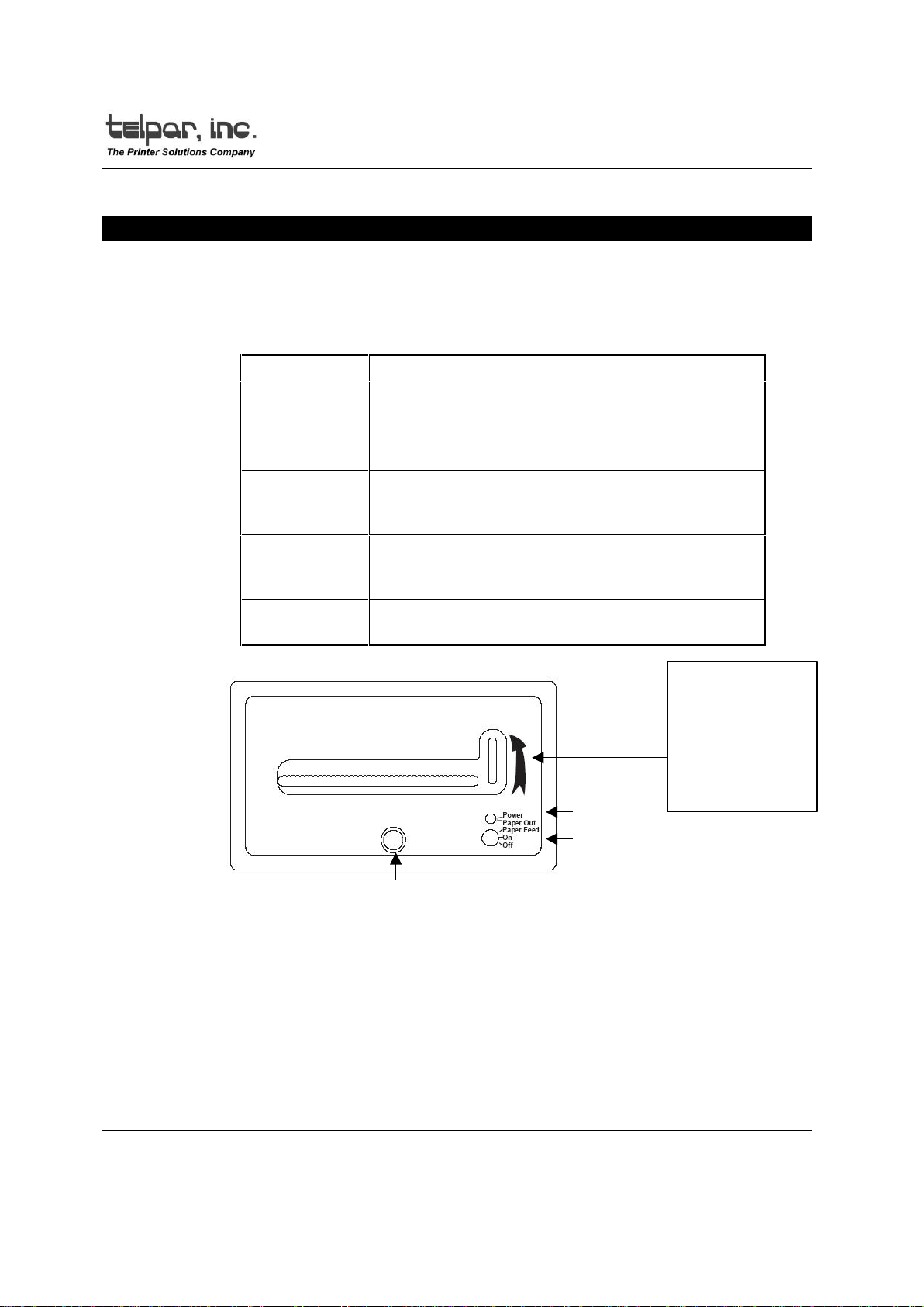
2 Operator Information .........................................................................................................4
2.1 Turn on and Self Test....................................................................................................4
2.2 Paper Loading ...............................................................................................................5
2.3 Journal Take Up............................................................................................................6
3 Installation.........................................................................................................................7
3.1 Unpacking and Inspection..............................................................................................7
3.2 Installation......................................................................................................................7
3.2.1 Serial RS-232 Interface Cable Suggestion .............................................................7
3.2.2 Parallel Interface Cable...........................................................................................8
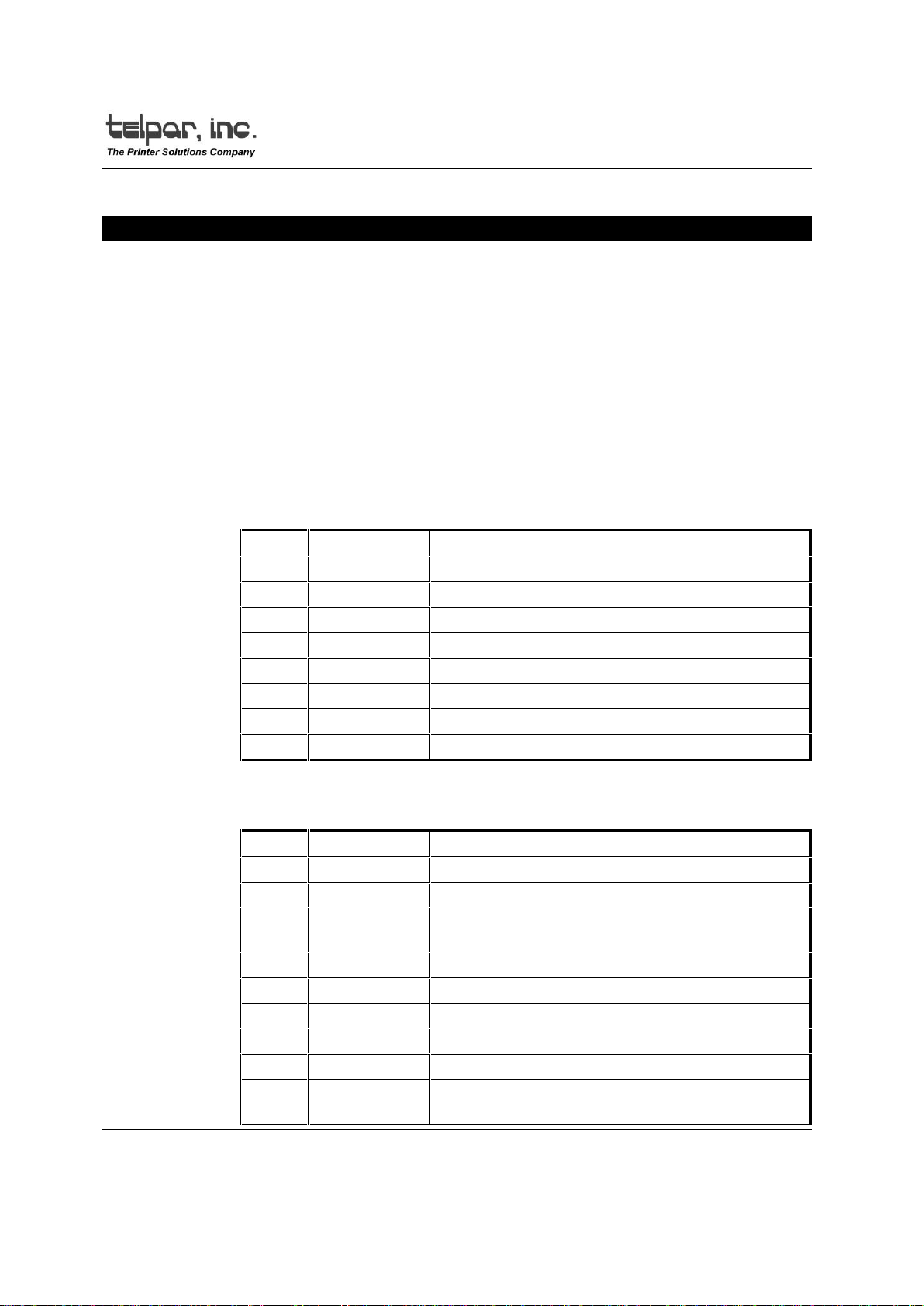
4 Interface Specifications.....................................................................................................9
4.1 Serial Interface...............................................................................................................9
4.1.1 Serial Interface Switch Settings ............................................................................10
4.2 Parallel Interface..........................................................................................................11
4.3 Flow Control.................................................................................................................11
5 Programming Information................................................................................................12
5.1 General........................................................................................................................12
5.2 Printable Characters....................................................................................................12
5.3 Graphics Mode.............................................................................................................12
5.4 Text Mode/Data Mode..................................................................................................13
5.5 Real Time Clock Option...............................................................................................13
5.6 Auto Time and Date.....................................................................................................13
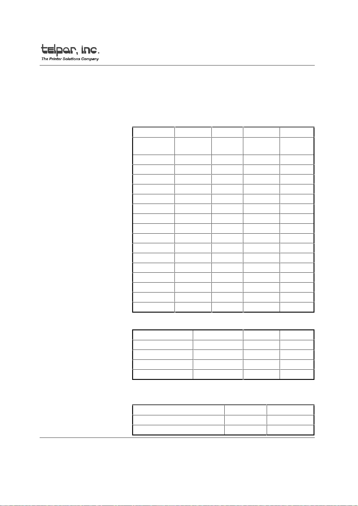
5.7 International Character Sets ........................................................................................13
5.8 Control Codes and Escape Sequences.......................................................................14
5.9 Test Program...............................................................................................................15
6 Maintenance....................................................................................................................16
6.1 Introduction..................................................................................................................16
6.2 Required Tools and Supplies.......................................................................................16
6.3 Cleaning.......................................................................................................................16
6.4 Maintenance Chart.......................................................................................................16
6.5 Warranty......................................................................................................................17
Appendix A. Printable Characters...........................................................................................18
Appendix B. Jumper Designations..........................................................................................19
Appendix C. Specifications.....................................................................................................20
Appendix D. Dimensions ........................................................................................................21
Appendix E. Cleaning Procedure ........................................................................................... 22

SP-401 User Manual
Telpar, Inc. Page 3 of 25
1 Introduction
This manual contains installation, operating and maintenance procedures for the
Telpar SP-401 series of low cost miniature thermal printers. The SP-401 printers are
available in 20 and 40 column Graphics and Non-Graphics configurations. These
printers are microprocessor controlled to provide a wide range of printing capabilities.
The SP-401 series of printers are small size and of a rugged design, which makes them
ideal for mobile use. In their standard configuration, they may be powered from any AC
or DC power source between 8 and 30 volts. A 115 VAC power supply is available as
an extra cost option, and also a 230 VAC power supply can be ordered as an option.
The SP-401 printers utilize a thermal print head to print dot matrix characters.
International character sets are supported by the SP-401 printers. The serial interfaces
support data rates of 50 to 19200 baud. The parallel interface is a Centronics type
which is compatible with the parallel printer ports on most personal computers.
The SP-401 series of printers may be ordered with a variety of options. Options are
a real time clock, bit image graphics mechanism, paper low sensor, and a paper take
up journal. Please contact Telpar for details regarding these options.
The SP-401 printer is available with either an RS232/20ma loop interface, an RS-
485/20 ma loop interface, or a parallel interface.
SP-401, Usage in a Windows Environment
Printing in a Windows environment consists of sending data to the printer in
a BIT-MAPPED GRAPHICS format. Since the printer mechanisms used in the
SP-401 series of printers do not have enough resolution to print graphics well,
no Windows drivers have been written for the SP-401 series of printers and
none are currently planned.
However, testing has shown that the SP-401 series of printers CAN be used
for printing TEXT in a Windows environment by selecting the Generic/Text Only
printer driver which is furnished with Windows. Select the Generic/Text Only
driver and then use ONLY the Roman 10 cpi font. Any graphics images
imbedded in a document (including True Type fonts) will be ignored when the
document is sent to the printer. PAGE SET-UP for using the SP-401/40 column
wide printer is to set all margins to 0 and select a paper width of 4 inches. PAGE
SET-UP for using the SP-401/20 column wide printer is to set all margins to 0
and select a paper width of 2 inches.

SP-401 User Manual
Telpar, Inc. Page 4 of 25
2 Operator Information
2.1 Turn on and Self Test
The operating controls of the SP-401 have been kept to a minimum. A
convenient self test feature allows the operator to quickly determine that the
printer is operating correctly. The functions of operating controls are as follows:
Control Function
Thumb Wheel Used on non-graphic model SP-401 printers to
advance the paper.
Do not rotate thumbwheel in a downward motion,
this will damage the paper feed mechanism.
L.E.D. Indicates power on and paper installed when
green, paper out when flashing red and green,
optional paper low when red.
Switch Power off in down position, Power on in middle,
and paper advance in the top (spring loaded)
position.
Latch To secure the main body of the printer to the
mounting box.
Figure 1 - SP-401 Front Panel
To activate the self test feature, shut the printer off, then in one quick motion,
move the power switch to the paper advance position and hold it there until the
self test text begins. Once the self test routine begins you may let go of the switch
and let the printer finish the self test. To stop the self test before the end of the
message, power down the printer.
For units with Debug Function Test Software (Firmware versions 9.0 and
above) The self test stops after 7 lines are printed and the printer is set to debug
mode. Data sent to the printer while it is in debug mode will be printed out (by the
printer) in the format as sent to the printer. ASCII printable characters (21 through
THUMBWHEEL IS
AVAILABLE ON NON-
GRAPHICS
VERSIONS ONLY
ARROW SHOWS
DIRECTION TO TURN
WHEEL - TURNING IT
BACKWARDS WILL
CAUSE DAMAGE
LED
SWITCH
LATCH

SP-401 User Manual
Telpar, Inc. Page 5 of 25
7 F hex) will be printed out as the actual character for readability 20 hex, the
space character is printed as a rectangle. Non-printable characters will be printed
in Hexadecimal form with a < before and a > after the hexadecimal code. To end
the debug function, power down the printer.
For the highest quality output and maximum thermal head life, it is
recommended that Telpar paper be used.
2.2 Paper Loading
Rotate the printers Front Panel Latch counter clockwise to release the printer
from the panel mount box. Once released, slide the printer out of the box for
paper loading. Install the paper spindle into a the roll of thermal paper. Position
the roll of paper so that it will feed from the top, then place the roll and spindle
into the paper support brackets, making certain that the paper is level. It is
recommended that the paper be cut back beyond and tape or glue residue and
then cut into an arc before feeding into the printer mechanism. (Note: Scissors cut
is preferred).
To load paper, turn on the power. Now feed the cut edge of the paper into the
guide until the paper stops. This printer will automatically feed the paper 10 line
feeds when the optical sensor detects paper. At this time it is recommended that a
self test be performed to ensure that the paper is installed correctly, (thermal side
up) and that it is feeding properly. The printer may now be installed back into the
panel mount box. Slide printer into the panel box unit fully seated. Rotate the
Front Panel Latch clockwise to fasten the printer in place with the box.
In the event of a paper jam condition do not force paper into the unit, or try to
pry the paper out of the unit, this may damage the thermal print mechanism.
Disconnect primary power and interface cable before servicing the unit. Open
printer and remove the face plate by removing the two 4/40 nuts on the back of
the face plate, this will allow access to the printer mechanism. Carefully remove
paper with a set of tweezers, or a small pair of needle-nose pliers. Once paper is
cleared from the mechanism, re-assemble the unit. At this time, re-load the paper.
Example of arc cut
leading edgeDirection of feed

SP-401 User Manual
Telpar, Inc. Page 6 of 25
2.3 Journal Take Up
The SP-401 printers are offered with a Journal Take Up as an option. Paper
should be loaded onto the journal only after a self test is performed to ensure that
the printer functions properly. The journal take up is activated automatically when
the printer performs a carriage return or line feed. To install paper onto the take
up journal, feed paper successfully through the printer mechanism to allow
approximately 4 inches of paper to feed out of the face plate. Position the take up
journal to show the pinch rod on top. Unscrew the fastener on the right side of the
take up journal and remove the right side disk and pinch rod assembly. Drape
paper under the guide rod and over the top of the take up journal spinde, then
reinstall right side disk and pinch rod. Paper should be repositioned between the
take up journal and the pinch rod at this time. Power printer and press the paper
advance to remove slack in the paper.
Figure 2 - SP-401 Paper Feed

SP-401 User Manual
Telpar, Inc. Page 7 of 25
3 Installation
3.1 Unpacking and Inspection
Carefully unpack and inspect your SP-401 for any damage which may have
occurred in transit. Should any damage have occurred, notify Telpar, save the
shipping carton and packing materials, and file a damage claim with the carrier.
Specify the nature and the extent of the damage.
Before installing or operating the printer, check the following:
1. Ensure that the primary power setting is correct for your installation.
2. Ensure that the printer mechanism and paper path are clear of all
packing materials or other foreign matter.
3. Ensure that paper is installed. Do not operate the printer without
paper. Refer to Section 2.2 for paper loading instructions.
3.2 Installation
3.2.1 Serial RS-232 Interface Cable Suggestion
Connect the data interface cable to the SP-401; if the RS-232
interface has been selected use a null modem cable to connect to
the host. If the current loop interface has been selected, a cable will
need to be locally fabricated. A suggested cable diagram is shown
below. For more information on communication signals see section
4.1.
COMPUTER DB9 PRINTER DB25
2 RXD 2 TXD
3 TXD 3 RXD
4 DTR 6 DSR
5 COM 7 COM
6 DSR
8 CTS 11 BUSY

SP-401 User Manual
Telpar, Inc. Page 8 of 25
3.2.2 Parallel Interface Cable
This parallel cable configuration is used to interface the SP-401
with all IBM and IBM compatible systems. This cable connects the
interface to the printer with a 1:1 cable connection, and is terminated
by a DB-25P on each end. This 25 pin cable configuration is
available at most computer supply stores. Ex. Pin 1 to pin 1, pin 2 to
pin 2, pin 25 to pin 25. Note: Cable length for the standard mode of
parallel printing should be limited to 25 feet or less.
Note: Cable length for the standard mode of parallel printing
(through MS-DOS) should be limited to 25 feet or less.

SP-401 User Manual
Telpar, Inc. Page 9 of 25
4 Interface Specifications
4.1 Serial Interface
The interface connector is located on the rear of the SP-401 printers.
Connector P1 is the serial port. Pin assignments are shown below. See Appendix
B for details.
Note: A valid baud rate must be set at all times for proper printer operation.
See section 4.1.1 for switch settings.
The SP-401 has two types of serial interfaces, RS-232 and 20 mA current
loop RS-485 & 20mA current loop. In general, the RS-232 interface is preferable if
the printer is located close to the host computer and can be connected with a
cable run of 50 feet or less.
RS-232/20 mA Interface
Pin Signal Description
1 GROUND Protective ground
2 TXD Data output from the printer to the host
3 RXD RS-232 data input, or 20mA positive input
5 CTS Inhibits TXD line when held at -10v by the host
7 GROUND Signal ground
11 BUSY -10v when printer is unable to receive data
20 DTR +10v when printer is on line
22 RET -20mA current loop return
RS-485/20 mA Interface
Pin Signal Description
1 DTR -
2 DTR +
3 20 mA
positive input
7 TXD -
8 TXD +
10 GND
19 RD -
20 RD +
22 20Ma
RETURN 20 Ma current loop RETURN

SP-401 User Manual
Telpar, Inc. Page 10 of 25
4.1.1 Serial Interface Switch Settings
The data word parameters must be set in the printer to
correspond with the settings of the host computer. These are set
using the DIP switches SW1 located on the back of the SP-401
chassis. See Appendix B for a visual aid.
Set the baud rate using SW1-5 through SW1-8 according to the
table below.
SWITCH SW1-8 SW1-7 SW1-6 SW1-5
BAUD
RATE
50 ON ON ON ON
75 OFF ON ON ON
110 ON OFF ON ON
134.5 OFF OFF ON ON
150 ON ON OFF ON
300 OFF ON OFF ON
600 ON OFF OFF ON
1200 OFF OFF OFF ON
1800 ON ON ON OFF
2000 OFF ON ON OFF
2400 ON OFF ON OFF
3600 OFF OFF ON OFF
4800 ON ON OFF OFF
7200 OFF ON OFF OFF
9600 ON OFF OFF OFF
19200 OFF OFF OFF OFF
Set the stop bits, data bits and parity using SW1-1 through 4
according to the table below.
Switch Function Off On
SW1-1 Stop bits 2 1
SW1-2 Data Bits 8 7
SW1-3 Parity Enable Disable
SW1-4 Parity Even Odd
Select current loop or RS-232 interface using JP2 and JP3 on the
component side of the back board. See Appendix B for a visual aid
for proper jumper placement.
Jumper RS-232 20 mA
JP3 pins 1,2 pins 2,3
JP2 pins 1,2 pins 2,3

SP-401 User Manual
Telpar, Inc. Page 11 of 25
4.2 Parallel Interface
A DB 25S connector (P1) is used for the parallel interface. The pin
assignments and brief signal descriptions are listed below.
Pin Signal Description
1 STROBE 1 usec. Pulse to clock data into the
printer
2 DATA 0
3 DATA 1
4 DATA 2 Eight data bit input signals to the printer;
5 DATA 3 Signal levels are high for logic 1 and low
6 DATA 4 for a logic 0.
7 DATA 5
8 DATA 6
9 DATA 7
10 ACK 6 usec pulse from printer when data
received
11 BUSY High when printer is unable to receive
data
12 PE Always low. There is no PAPER ERROR
signal supplied at the parallel interface
13 SELECT High when printer is on line
18-24 GROUND Signal Grounds
4.3 Flow Control
The SP-401 printers employ a 7K byte data buffer as a standard feature to
allow the host computer to rapidly transfer data. Under some circumstances it
may be possible to completely fill the 7K buffer. When the buffer is within 50
bytes of being full, the SP-401 printers signal the host computer to pause until a
line of data is printed, or until the buffer is under the 50 byte limit. The flow control
information is sent to the host using hardware and software protocols.
The hardware protocol uses the BUSY line of the parallel interface or the
BUSY line of the serial interface. These pins are asserted or negated as
necessary to turn off and turn on the flow of data. The software protocol (Serial
interface only) uses the XON and XOFF ASCII characters (^Q and ^S) which are
sent back to the host to start and stop the data stream. Some host systems may
not support one or both of these protocols.

SP-401 User Manual
Telpar, Inc. Page 12 of 25
5 Programming Information
5.1 General
The SP-401 printers have several different operation modes. Standard
printers can print text and dot addressable graphics.
5.2 Printable Characters
When the SP-401 printers are initially powered up and placed on-line, their
default mode is to process incoming data as ASCII text characters and print them
out in the normal font. The standard printable character set is listed in Appendix A
of this manual.
5.3 Graphics Mode
The SP-401 Series printers can print dot addressable graphics. There is a
mechanism dedicated for graphics use which allows the dot lines to connect
vertically after a line feed. Please contact Telpar for details on this optional
mechanism. The host computer controls each dot printed and each dot directly
corresponds to one bit of a graphics byte.
The following sequence must be sent to the printer at the beginning of each
line of graphics. ESC+”S”+n1+n2+n3+n4 (256 Dot per Line)
The sequence ESC+”S” enables the graphics mode. The length of the bit
image data is declared by the digits n1, n2, n3, n4. The printer will return to the
character mode once the number of graphics characters has been printed.
Graphics data sent after the maximum number of columns has been reached will
be truncated.
An example of graphics where 192 bytes of bit image data are input as
follows: 1BH, 53H, 30H, 31H, 39H, 32H, = ESC+”S”+0+1+9+2
The relationship between graphics data and the printer dot head is as follows:
Print Head Graphics Data
1 (Top) DO (LSB)
2 D1
3 D2
4 D3
5 D4
6 D5
7 D6
8 (Bottom) D7 (MSB on graphics models only)

SP-401 User Manual
Telpar, Inc. Page 13 of 25
5.4 Text Mode/Data Mode
The SP-401 printers can print in either Text mode or Data mode. To print in
Data mode shut off printer and jumper pins 1&2 of header P1 on the main board.
The printer will remain in this print mode until the jumper P1 is removed. The
difference between Text Mode printing and Data Mode printing is that Text Mode
print is upside down and right to left when exiting the printer, Data Mode is right
side up and left to right when exiting the printer. See Appendix B for a visual aid
on jumper placement.
5.5 Real Time Clock Option
The SP-401 is capable of printing the time and date on command with the
installation of the Real Time Clock Option. To display the time that is currently set,
the printer must receive the control code 05 decimal, (05) hex. To set the time to a
new value the printer must receive the escape sequence ESC,t and the new
parameters in the following format; hh:mmA (hrs:minutes A for am., P for pm., ex.
12:22P. To display the date that is currently set, the printer must receive the
control code 06 decimal, (06) hex. To change the value of the date that is
currently set, the printer must receive the escape sequence ESC,d and the new
parameters in the following format; mm-dd-yy (month-day-year), ex. 01-22-95.
5.6 Auto Time and Date
The auto time date option can only be used in conjunction with the real time
clock option. This feature allows the time and date to be printed automatically
after the printer has received a carriage return. To enable this feature, jumper pins
1 and 2 of header JP6 on the serial interface board, or pins 1 and 2 of header
JP4 on the parallel interface board. (back board) See Appendix B for a visual aid
on jumper placement.
5.7 International Character Sets
International Character Sets are available for the SP-401 series printers.
Standard printers are initialized with the U.S.A. character set. Once a set has
been changed to another the printer will stay in that character set until another set
is chosen, or the printer is powered down. To change the international character
the printer must receive the following ESC sequence: ESC+”R”+n (n=0-6). See
the list below for the n character set designations.
n NATION n NATION
0 JAPAN 4 SWEDEN
1 FRANCE 5 ITALY
2 GERMANY 6 U.S.A.
3 U.K. 7 CUSTOM

SP-401 User Manual
Telpar, Inc. Page 14 of 25
5.8 Control Codes and Escape Sequences
Category Symbol Decimal
(hex) Function
Control Code PRNT_T 05 (05) * Display Time (optional)
PRNT_D 06 (06) * Display Data (optional)
Bell 07 (07) Causes a “flash” of power/paper
out led.
Asterisk LF 10 (OA) Single Line Feed
Denotes CR 13 (OD) Carriage Return (print buffer)
Optional SO 14 (OE) Double Width Print On
Codes SI 15 (OF) Double Width Print Off
RESET
(CAN) 24 (18) Clears all Data from Print Buffer
ESC 27 (1B) Escape
ESC
Sequence ESC,S
ts 83 (53) Enables Bit Image Graphics (256
Byte max.) See Section 5.3
ESC,d
ts 100 (64) * Set Date Format mm-dd-yy
ESC, t
ts 116 (74) * Set Time Format hh:mmA A for
am P for pm

SP-401 User Manual
Telpar, Inc. Page 15 of 25
5.9 Test Program
This is a test program written in BASIC for the SP-401 Parallel Interface
printer. This program will test the standard control code and escape sequences
executed by the SP-401.
10 CLS
20 WIDTH LPRINT 255 :REM sets output line width
30 LPRINT CHR$(14) :REM double width print on
40 LPRINT”SP-401”
50 LPRINT”THERMAL PRINTER”
60 LPRINT CHR$(15) :REM double width print off
70 LPRINT”Telpar”
80 LPRINT”4181 Centurion Way”
90 LPRINT”Addison TX 75244’
100 LPRINT”(972) 233-6631”
110 LPRINT CHR$(10) :REM single line feed
120 LPRINT
130 LPRINT
140 LPRINT”THIS IS A GRAPHICS TEST”
150 LPRINT CHR$(27)+”S0255” :REM Length=255
160 FOR X=1 TO 255
170 LPRINT CHR$(255): :REM fires all dots
180 NEXT X
190 LPRINT
200 LPRINT
210 CLS
220 LPRINT”CLOCK TEST” : REM(Note: The Clock Mode is Optional)
230 PRINT”PLEASE HAVE YOUR PRINTER TURNED ON TO SET THE
TIME/DATE”,CHR$(10)
240 FOR X=500 TO 10000 STEP 300:SOUND X,2:NEXT X
250 LPRINT CHR$(14);”CLOCK TEST”
260 LPRINT CHR$(15)
270 INPUT”DO YOU WISH TO CHANGE THE TIME? (Y/N)”;Y$:CLS
280 IF Y$=”N”OR Y$=”n” THEN GOTO 330
290 LPRINT”THE TIME CURRENTLY SET IS”;CHR$(5)
300 PRINT”ENTER TIME AS hh:mmA (hours:minutes A for am P for pm)”
310 INPUT A$
320 LPRINT CHR$(27)+”t”;a$;”THE NEW TIME IS”
330 LPRINT CHR$(14);CHR$(5)
340 LPRINT CHR$(15)
350 INPUT”DO YOU WISH TO CHANGE THE DATE? (Y/N)”;Y$:CLS
360 IF Y$=”N” OR Y$=”n” THEN GOTO 410
370 LPRINT”THE DATE CURRENTLY SET IS”;CHR$(6)
380 PRINT”ENTER THE DATE IN THE FOLLOWING FORMAT mm-dd-yy (month-day-year)”
390 INPUT A$
400 LPRINT CHR$(27)+”d”;A$;”THE NEW DATE IS”
410 LPRINT CHR$(14);CHR$(6)
420 LPRINT CHR$(15)
430 END

SP-401 User Manual
Telpar, Inc. Page 16 of 25
6 Maintenance
6.1 Introduction
The SP-401 printers are designed to require a minimum of maintenance and
service. This section provides instructions for cleaning and maintenance.
Electrical and mechanical repairs should be performed by qualified personnel
only. Make certain that all electrical connections are disconnected before any
service is performed on the SP-401 printers.
6.2 Required Tools and Supplies
1. Common hand tools
2. Denatured alcohol
3. Cleaning rags
4. Cotton swabs
5. Lubricant IBM #23, LUBRIPLATE #70, SILCON#35
6.3 Cleaning
The SP-401 exterior cabinet may be cleaned with a non-abrasive cleanser.
Care should be taken to prevent liquids from entering inside the mechanical
assembly. If in a dirty environment the mechanism may be removed and the parts
may be cleaned with alcohol and a cotton swab. The mechanism may also be
“blown out” with compressed air. Do not direct air flow to printer platen, this may
remove the soft rubber printing surface from the platen. When the mechanism is
clean and free of dirt, a light silicon lubricant may be applied (sparingly) to the
moving mechanical components.
6.4 Maintenance Chart
Clean Office
or
Light Use Once Per Year
Clean Factory
Environment
Medium Use Monthly
Dirty Factory
Environment
Heavy Use Weekly

SP-401 User Manual
Telpar, Inc. Page 17 of 25
6.5 Warranty Telpar — Printer Limited Warranty
For one (1) year after shipment of the printer product to Buyer, Telpar warrants the product
against defects in materials and workmanship provided the product has been operated and
maintained in accordance with manufacturer’s operating and maintenance specifications. This
warranty specifically excludes ribbons, paper and other consumable items.
THIS WARRANTY IS IN LIEU OF ANY AND ALL OTHER WARRANTIES, EXPRESSED OR
IMPLIED. TELPAR MAKES NO OTHER WARRANTY AND BUYER SPECIFICALLY WAIVES
ANY OTHER WARRANTIES, INCLUDING WARRANTIES OF MERCHANTABILITY OR
FITNESS FOR A PARTICULAR PURPOSE. THERE ARE NO WARRANTIES THAT EXTEND
BEYOND THOSE DESCRIBED HEREIN.
Telpar’s liability hereunder is limited to the repair or replacement of defective parts. This liability
does not extend to normal wear and tear. Telpar will, solely at its option, remedy all valid
warranty claims either by:
(a) Repairing or replacing the defective unit at Telpar’s factory; or
(b) Repairing or replacing the defective subassembly at Telpar’s factory.
If so directed by Telpar, Buyer shall return the defective unit or subassembly, transportation
prepaid by Buyer, to Telpar’s factory. After repair or replacement has been accomplished,
Telpar will return the unit or subassembly, transportation prepaid by Telpar, to Buyer.
As a precondition to any warranty service, prior to return of any units or subassemblies to
Telpar by Buyer, Buyer must contact Telpar’s Order Administration Services and receive
authorization in the form of a Return Material Authorization (RMA) number. Telpar reserves the
right to refuse any goods it has not previously authorized for return, or any goods shipped
without transportation prepaid.
No warranty shall apply to any damage resulting from or caused by Buyer, if Buyer shall make
any changes, modifications, additions or deletions of hardware, software or firmware in the
Printer products sold hereunder without Telpar’s advance written consent.
Upon receiving an RMA from Telpar, warranty service may be obtained by returning the
merchandise, freight prepaid, with a copy of your invoice.
Telephone: 800-872-4886 or 972-420-4700
Fax: 972-420-4272
Email: info@telpar.com
Upon inspection, Telpar will make necessary repairs or replacement and return the
merchandise, shipping prepaid.

SP-401 User Manual
Telpar, Inc. Page 18 of 25
APPENDIX
Appendix A. Printable Characters
ASCII codes listed below are the printable ASCII characters for the SP-401 printers.
Decimal and Hexadecimal values are given.
Dec Hex Char Dec Hex Char Dec Hex Char Dec Hex Char
32 20 SP 56 38 8 80 50 P 104 68 h
33 21 ! 57 39 9 81 51 Q 105 69 I
34 22 “ 58 3A : 82 52 R 106 6A j
35 23 # 59 3B ; 83 53 S 107 6B k
36 24 $ 60 3C << 84 54 T 108 6C l
37 25 % 61 3D = 85 55 U 109 6D m
38 26 & 62 3E >> 86 56 V 110 6E n
39 27 ‘ 63 3F ? 87 57 W 111 6F o
40 28 ( 64 40 @ 88 58 X 112 70 p
41 29 ) 65 41 A 89 59 Y 113 71 q
42 2A * 66 42 B 90 5A Z 114 72 r
43 2B + 67 43 C 91 5B [ 115 73 s
44 2C , 68 44 D 92 5C \ 116 74 t
45 2D - 69 45 E 93 5D ] 117 75 u
46 2E . 70 46 F 94 5E ^ 118 76 v
47 2F / 71 47 G 95 5F _ 119 77 w
48 30 0 72 48 H 96 60 ‘ 120 78 x
49 31 1 73 49 I 97 61 a 121 79 y
50 32 2 74 4A J 98 62 b 122 7A z
51 33 3 75 4B K 99 63 c 123 7B {
52 34 4 76 4C L 100 64 d 124 7C |
53 35 5 77 4D M 101 65 e 125 7D }
54 36 6 78 4E N 102 66 f 126 7E ~
55 37 7 79 4F O 103 67 g 127 7F DEL

SP-401 User Manual
Telpar, Inc. Page 19 of 25
Appendix B. Jumper Designations
Main Controller Board (Top view) Serial RS-232/20mA Back Board
Figure 3 - Jumper Designations
Parallel Back Board
Mechanism Input
Optical Sensor
Paper Spindle
and Guides
P1
EPROM RAM
Z80 8255
P1
1
2
SW11
2
JP6
F1
=
2A C1
JP3 123
JP2 123
U1
232
SW1
JP1 3 1
4 2 JP1 BACK VIEW
PIN LAYOUT
JP2,JP3=Jumpers to change RS-232 to 20maloop interface.
Jumper pins 1 and 2 for RS-232.
Jumper pins 2 and 3 for 20ma operation.
JP6 = Auto Time and date after carriage return
F1 = 2 amp fuse
Jumper RS232 20mA
JP3 pins 1&2 pins 2&3
JP2 pins 1&2 pins 2&3
P1 = Data Mode/Text Mode (see section 5.4)
Open = Text Mode
Closed = Data Mode
JP1 = Power input 8 to 30 VAC/DC
Pins 1 & 2 AC
Pin 3, Negative DC
Pin 4, Positive DC
P1 1 2
JP4
X1
F1 = 2A
74LS373 C1
JP4 = AUTO TIME AND DATE
AFTER CARRIAGE RETURN
OPEN = DISABLE (JUMPER OFF)
CLOSED = ENABLE (JUMPER ON)

SP-401 User Manual
Telpar, Inc. Page 20 of 25
Appendix C. Specifications
Specifications SP-401 SERIES Thermal Printers
Performance:
Max. Print Rate 0.6 Lines/second
Line Density 6 Lines/inch
Print Head Life 500,000 character lines
Buffer Size 7000 character
General:
Number of Columns 20,40
Graphics 256 Byte Maximum
Print Modes Data or Text (Jumper Selectable)
Dot Diameter 0.014 inches (0.35mm)
Dot Spacing 0.014 in (0.35 mm) vertical, 0.010 in (0.25 mm) horizontal
Line Spacing 0.060 in (1.5 mm)
Paper Width Roll
Stock 80ft/roll 3.125 inches (79.4mm) Use Telpar Paper for Best Results
Temperature Range Operating: 0°to +50°C; storage -25°C to +85°C.,90% max.
RH (non condensing)
Power:
Voltage and Power 10 to 30 vac, 8 to 30 vdc 110 / 230 vac with wall adapters, 2.5
watts standby, 12 watts printing
Interface:
Serial RS-232/20 mA serial interface (DB-25S Connector)
RS485/20mA
Parallel Centronics Parallel Type (DB-25S Connector)
Mechanical:
Dimensions 2.7” H x 4.5” W x 5.7” D (68.6 mm x 114.3 mm x 144.8 mm)
Weight 2.25 lb. (1.02 kg.)
Table of contents
Other Telpar Printer manuals

Telpar
Telpar MTP-1500 User manual

Telpar
Telpar SP-328 User manual

Telpar
Telpar MTP-600 Series User manual

Telpar
Telpar SP-327 User manual

Telpar
Telpar MTP7632 Owner's manual

Telpar
Telpar MTP-2232 User manual

Telpar
Telpar MTP-1530II User manual

Telpar
Telpar SP-5000 User manual

Telpar
Telpar MTP-2822 User manual