Telpar SP-327 User manual

TELPAR
SP-327 Receipt Thermal Printer
For Sales, Technical Support, Warranty Returns and Repairs, please contact us at
800-872-4886
Please visit our website at any time at
www.telpar.com
© Copyright 2008, Telpar, Inc. All Rights Reserved
(Document Name and Revision: SP327Manual050808.doc)
187 Crosby Road
Dover, NH 03820

Telpar SP-327 Receipt Thermal Printer Summary
The TELPAR SP-327 Receipt Thermal Printer is a direct thermal printer designed as an
economical solution to the demands of unattended hardcopy devices and applications.
Applications include toll booth receipts, supermarket discount coupons, cash vouchers for
exchanged goods, automated collection machines, parking validation slips, gas station pump
receipts, and gaming machine receipts.
Printer Features:
• Durable All Metal Construction
• Automatic Paper Loading
• Low paper Roll Detection
• Error Status LED and Beeper
• Single Multifunction Power & Paper Feed Switch
• Serial Communication with Status Feedback Modes
• 8 Dots/mm (203 Dots/Inch) Thermal Print Head
• 56mm (2.2 inches) Total Printing Width
• Speeds of up to 10 Character-lines per Second (Ten full lines consisting of 24 characters / line)
• Durable Guillotine Cutter (400,000 Cut Operations Typically)
• 7K Character Buffer
• Four Standard Character Sets
• Raster Graphics
• Bar Coding Capabilities (Barcode 3 of 9 and Interleaved 2 of 5).
Thermal Paper unwinds from the
top of the roll with the thermal
coated side of the paper facing
down as shown.
To auto feed paper into the printer,
guide the leading edge of the paper into
the paper entryslot in the chassis until it
stops. Within a second, the printer
platen will automatically grab the paper
and feed approx. 1.5 inches of paper
through the printer and cutter sections.
Head-up Lever rotates up
to raise the thermal print
head off the paper to
assist in clearing paper
jams or quick paper
removal.
Serial Label information will be
used when requesting
Technical or Return / Repair
Assistance from Telpar.
Four Position Power Connector (right)
See Section 1 on Page 1 for Power Cable
Pinout.
Nine position RS-232 DB Sub-Connector
See Section 16 on Page 8 for Interface
Cable Pinout.
Three position Toggle Switch:
Full left position = OFF
Middle Position = ON
Full right position = Paper Feed
(Momentary)
Error Status LED

User Manual & Maintenance Manual Table of Contents
User Manual for the SP-327
Topic Description: Page
Number Section
Number
Power Requirements 1 1
Input Voltage Options 1 2
RS-232 Interface 1 3
Environmental 1 4
Control Codes & Escape Sequences 2 5
Echo Back Printer Error Status Byte 3 6
Echo Back Printer Mode Status Byte 3 7
Paper Cutter Features 3 8
Printer Mechanism Features 4 9
Controller Features 5 10
Self Test Mode 5 11
Default RS-232 Settings 5 12
Chassis / Mechanism Dimensions 6 13
Printed Circuit Board Dimensions 6 14
ERROR CODES (LED & Beeper Status) 7 15
Character Sizes for Various Fonts 7 15
Paper Roll Part Number for Reordering 7 15
Serial RS-232 Cable Pinout Suggestion 8 16
Sample Code in MS Visual Basic 6.0 9, 10 17
Maintenance Manual for the SP-327
Introduction
Cleaning
Cutter Assembly
Examples of Printing Problems
Maintenance Chart
MM1
MM2
MM3
MM4
MM5

1 ). POWER REQUIREMENTS:
The Table below shows both the peak and average amperages with their associated duty cycles for a typical SP-327 printer
performing various printing operations. The SP-327 operation requires large peak current pulses at low duty cycles.
Therefore, the average power requirement is typically low.
NOTE on GRAPHICS MODE CURRENT: The average current required in graphics mode is very low since it is limited
by the data transfer rate. The Graphics Command requires the transmission of at least 5 characters to print 8 dots on a line. A
baud rate set at 9600 (approx. 1 msec / char transmission time) produces a 0.1 amp peak or a 10 mAmp average at a 12% duty
cycle. The Graphics Command requires a minimum of 60 characters to print all 448 dots on a line. In this situation, a 6 amp
peak or 140 mAmp average is produced at a 2.3% duty cycle.
Font Type or
Operational Condition Maximum Peak Current Typical
Duty Cycle Average Current
24 Characters / Line
(Printing Full line of the letter ‘H’) 6.5 Amps 30% 2 Amps
48 Characters / Line
(Printing Full line of the letter ‘H’) 5.5 Amps 42% 2.3 Amps
Graphics (Fire ALL 448 dots) 6.0 Amps LOW Less Than 0.20 Amps
Idle (on but doing nothing) 0.070 Amps Typical NA NA
Paper Feeding (no print) 0.150 Amps Typical NA NA
2). INPUT VOLTAGE OPTIONS:
For most typical printing applications, the SP-327 standard input voltage rating is:
• 18 VAC rms power supply rated at least 20VA
OR
• 24 VDC regulated power supply rated at least 2.1Amps (50Watts)
An optional 115 V.A.C. wall transformer & Cable assembly is available àTelpar Part # 780327-0010.
Note: All raw input voltage options listed above are provided with input transient suppression circuitry that will
protect the print/cut mechanism and electronics from momentary over voltage conditions commonly found in
switching power supplies and vehicular power sources.
3). RS-232 INTERFACE:
The SP-327 comes standard with an RS-232C Bi-directional communication interface.
Default RS-232 Settings (in Standard Firmware) are the following:
Baud Rate = 9600 bps, 8 Data Bits, 1 Stop Bit, No Parity, and Hardware Handshaking.
An RS-232 Cable Pinout diagram can be found in section 16 (page 8).
4). ENVIRONMENTAL:
Normal operating temperature of the SP-327 is - 40°C to + 60° C (- 40°F to + 140°F).
The SP-327 has a compensating circuit that maintains print intensity for the temperature range specified above.
Page 1
Mating Connector and Terminal Socket Part Numbers:
1 Molex P/N 39-01-2045 or -2040 2x2 socket connector.
2 Terminals for above MolexP/N 44485-1211 or 1212 sockets.
Pin 1 = VAC or +24VDC Pin 2 = VAC or
DC Common
Connector Key
The diagram below shows the
FRONT FACE of the Power Supply
CABLE CONNECTOR which mates to
the SP-327 Power Connector:

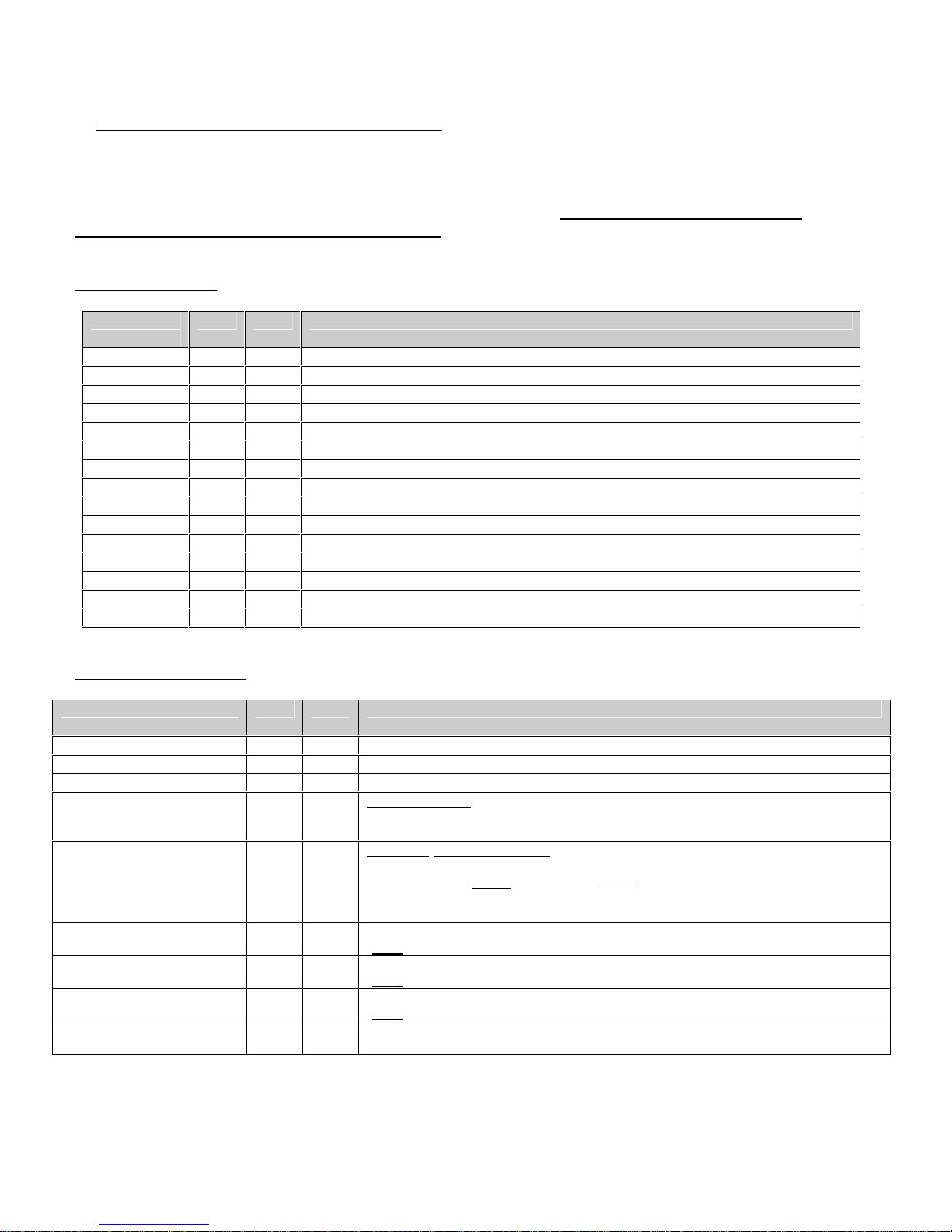
5) CONTROL CODES and ESCAPE SEQUENCES
The TELPAR Model SP-327 uses the following Control Codes and Escape Sequences to control special features of
the printer such as printing in landscape mode, condensed mode, printing barcodes (3 of 9 and I 2of 5 only),
performing a paper cut, and many other features. The tables below describe these codes and sequences and what
they do. For examples of using some of these codes and sequences, please see section 17 for sample
programming code written in MS Visual Basic 6.0.
CONTROL CODES:
Control
Code HEX DEC Description
STX 02H 2 Landscape Print, Start of Text (ie. Print rotated 90 degrees)
ETX 03H 3 Landscape Print, End of Text (ie. Print rotated 90 degrees)
RLF 08H 8 Reverse Line Feed (one line feed space – registration after may not be exact)
SLF 0AH 10 Single Line Feed – feeds amount of paper as specified by ESC ”3” n (see table below)
PT 0DH 13 Print Command – allows information from host to be printed to the printer
SO 0EH 14 Enable Double Width Print
SI 0FH 15 Enable Condensed Print
DBLH 10H 16 Enable Double Height Print
NDBH 11H 17 Disable Double Height Print
DC2 12H 18 Disable Condensed Print
S_REQ 13H 19 Ask for Printer Status (Error Status) See Section 6
DC4 14H 20 Disable Double Width Print
M_REQ 15H 21 Ask for current Print Mode, See Section 7
CAN 18H 24 Clears all data in the buffer
ESC 1BH 27 Escape Bit
ESCAPE SEQUENCES:
Escape
Sequence HEX DEC Description
ESC “@” 40H 64 Reset Printer (clears all data in the buffer)
ESC ”3” n 33H 51 Set Line feed space to n * 0.0097 Inches (Default n = 4). See SLF in Table above.
ESC “c” 63H 99 Initiate a paper cut
ESC “C” n1 n2 Data CR 43H 67 Bar Code 3 of 9.n1 = Indent space from margin in mm,
Height of Barcode = n2 * 4mm (n2 must be > 0. Therefore, the smallest barcode
height = 4mm).
ESC “i” n1 n2 Data CR 69H 105 Bar Code Interleaved 2 of 5.n1 = Indent space from margin in mm,
Height of Barcode = n2 * 4mm (n2 must be > 0. Therefore, the smallest barcode
height = 4mm). NOTE: Use only an EVEN number of data bytes àthe printer will
generate an error message if either an odd number of data bytes or an illegal
character is received.
ESC “h” n 68H 104 Fill n bytes of space (blank) in when using raster graphics.
(Note: Print Density = 8 Dots / mm, Printing width = 56mm, or 448 Dots per Line)
ESC “j” n 6AH 106 Perform n dot steps.
(Note: Print Density = 8 Dots / mm, Printing width = 56mm, or 448 Dots per Line)
ESC “l” n Data 6CH 108 N bytes of raster graphics.
(Note: Print Density = 8 Dots / mm, Printing width = 56mm, or 448 Dots per Line)
ESC “r” n 72H 114 n = 0 to set light print
n = 1 to set dark print
Page 2

6). ECHO BACK PRINTER ERROR STATUS BYTE:
The user has the option of polling the printer for error status. This is accomplished by sending the printer the control code
S_REQ 13H. The printer will then transmit back to the host the following one byte status:
BIT WEIGHT DESCRIPTION
0 Paper Low = 1
1 Paper Out = 1
2 Cutter Jam = 1
3Not used
4Not used
5 Buffer Full = 1
6 Buffer Empty = 1
7Not used
7). ECHO BACK PRINTER MODE STATUS BYTE:
The user has the option of polling the printer for mode status. This is accomplished bysending the printer the control code
M_REQ 15H. The printer will then transmit back to the host the following one byte status indicating the current print
modes:
BIT WEIGHT DESCRIPTION
0 Landscape Print ON = 1
1 Double Wide ON = 1
2Not used
3 Double High ON = 1
4 2 of 5 Bar-code ON = 1
5Not used (always = 0)
6Not used (always = 0)
7 Condensed Print ON = 1
8). PAPER CUTTER FEATURES:
• The SP-327 is equipped with a long life guillotine paper cutter that is user activated via the escape code ESC c.
• The printer controller board monitors the paper cutter's home switch. If the cutter blade is not on the home position
(example: due to tampering), then the controller card will energize the cutter and home the guillotine blade.
• When the cutter is energized, an internal watch timer is set for 1 second. If the cutter blade does not reach the home
position within this allotted time the controller board will set bit 2 of the STATUS byte to a logic one indicating a
cutter jam has occurred. The same condition will occur if the cutter blade overshoots the home position.
• Also provided is a solid state thermal overload circuit for the cutter (this is to protect the cutter motor from a locked
rotor or micro processor malfunction).
• The paper cutter's MTBF( mean time between failure) is 400,000 cuts .The MTBF may be severely shortened if
TELPAR paper is not used. Contact TELPAR for replacement paper (see section 15 on page 7 for the part number for
replacement Telpar paper for the SP-327).
Page 3

9) PRINT MECHANISM FEATURES:
• 8 Dots/mm (203 Dots/Inch) Thermal Printhead
• 56mm (2.2 inches) Total Printing Width
• Mechanical dot density is 448 dots per line
• Print speeds of up to 10 character-lines per second (10 full lines consisting of 24 characters per line)
• Integrated Paper Out / Top of Form Sensor
• Embedded Thermistor for monitoring Print Head Temperature
• One piece cutter / mechanism assembly with tapped holes for easy mechanical mounting and service.
Page 4

10). CONTROLLER FEATURES (Circuit Board Assembly):
• Standard 7K ram buffer
• Socketed External program EPROM
• Print head protected by a power switch watch dog timer
• OPTIONAL dip switch selectable baud rate (100-38.4 k bps)
11). SELF TEST MODE:
The SP-327 has a self test mode that will print and cut a sample ticket utilizing all of its control code features. The printer
does NOT have to be connected to the host via the serial port to print a Self Test ticket.
NOTE: The printer’s Power / Feed Switch has three valid positions of operation: OFF,ON (middle position), and
PAPER FEED (the Paper Feed position is temporary – the switch should spring back into the ON position whenever the
switch is released from the Paper Feed position).
To place the unit into self test mode, first turn the power switch to the off position. Next, push the power switch all the way
over to the Paper Feed position. Release the switch after one second, and a self test sample will be printed and cut. All
electrical/mechanical portions of the printer are exercised and checked by this action.
12) SP327 Standard Default RS232 Parameters
(Fixed in Firmware on all standard Models)
NOTE: Custom Firmware may use different parameters based on customer request
Baud Rate 9600
Parity NONE
Data Bits 8 Data Bits
Stop Bits 1 Stop Bit
Flow Control Hardware
Page 5.


15.) SP327 Error Codes (Lights and Beeper Status)
LED BEEPER
No Paper in Mechanism (Head Closed) Green / Red Flashes ½ Sec Pulses
Head Up Green / Red Flashes ½ Sec Pulses
Cutter Not Home Solid Green Very Fast Pulses
Paper Roll Low *Solid RED OFF
Normal (Ready) w/ Paper Solid Green OFF
* The Paper Roll Low indication will activate when the diameter of the paper roll
decreases to approximately 43mm (approx. 1.7 inches).
Character Sizes for Various Fonts:
Font Type Characters / Line Lines / Inch
Normal (Default) 24 6.2
Normal Double Wide 12 6.2
Normal Double High 24 4.2
Normal Double Wide & Double High 12 4.2
Condensed 48 11.8
Condensed Double Wide 24 11.8
Condensed Double High 48 6.2
Condensed Double Wide & Double High 24 6.2
PAPER:
The recommended thermal paper for use with the Telpar SP-327 is Telpar Part # 751327-0030.
Please contact Telpar Sales when ordering this paper.
Page 7

16)Serial RS-232 Interface Cable Suggestion:
Computer End of Cable (Host) Side TELPAR Printer End of Cable
(9 Position, Female D-Sub Connector) (9 Position, male D-Sub Connector)
Socket Position Pin Position
1 1
2 2
3 3
4 4
5 5
6 6
7 7
8 8
9 9
Page 8
Transmit Receive
Receive Transmit
Signal Common Line
CTS Printer Busy Line
DTR
DSR
Jumper

'Telpar SP-327 sample test code written in MS Visual Basic 6.0
' The MSComm Control must be used and setup to run this program
' Use COM1 Port for RS-232 Communications.
MSComm1.CommPort = 1
' 9600 baud, no parity, 8 data, and 1 stop bit.
MSComm1.Settings = "9600,N,8,1"
' Tell the control to read entire buffer when Input is used.
MSComm1.InputLen = 0
' DSR Timeout in mSec
MSComm1.DSRTimeout = 50
' CTS Timeout in mSec
MSComm1.CTSTimeout = 50
' Open the port.
MSComm1.PortOpen = True
' CTS Holding State
CHolding = MSComm1.CTSHolding
Debug.Print "MSComm1.CTSHolding = " + Str$(MSComm1.CTSHolding)
' DSR Holding State
DHolding = MSComm1.DSRHolding
Debug.Print "MSComm1.DSRHolding = " + Str$(MSComm1.DSRHolding)
If MSComm1.DSRHolding = False Then
MSComm1.PortOpen = False
GoTo SerialOpps
End If
MSComm1.Output = Chr$(10)
MSComm1.Output = Chr$(13)
'Example of Error Status Checking
MSComm1.Output = Chr$(19) 'Get Error Status
While (MSComm1.InBufferCount <= 0)
NahDah = DoEvents() ‘prevents program from being locked in an infiniteloop
Wend
'Read Status
A$ = MSComm1.Input
Debug.Print "Status = *" + A$ + "*"
Status$ = Hex$(Asc(A$))
If Right$(Status$, 1) = "0" Then
MSComm1.Output = "Status: PRINTER READY!"
MSComm1.Output = Chr$(10) 'Line Feed
MSComm1.Output = Chr$(13) 'Carriage Return
MSComm1.Output = Chr$(10)
MSComm1.Output = Chr$(13)
End If
'If there is an error, then Debug.Print info to VB's Immediate Window. Ref User Manual Section 6.0:
If Right$(Status$, 1) = "1" Or Right$(Status$, 1) = "3" Or Right$(Status$, 1) = "5" Or Right$(Status$, 1) = "7" Then Debug.Print "PAPER LOW
SENSOR DOES NOT SEE PAPER ROLL."
If Right$(Status$, 1) = "2" Or Right$(Status$, 1) = "3" Or Right$(Status$, 1) = "6" Or Right$(Status$, 1) = "7" Then Debug.Print "PAPER OUT
LEVER ON PRINTER MECH MAY BE IN THE PAPER RELEASE POSITION."
If Right$(Status$, 1) = "4" Or Right$(Status$, 1) = "5" Or Right$(Status$, 1) = "6" Or Right$(Status$, 1) = "7" Then Debug.Print "POSSIBLE
CUTTER PROBLEM!"
'Example of the SP-327 Graphics Mode Checker Board
For y = 1 To 3
For x = 1 To 10
' Raster Graphics --> ESC + "l" + #of bytes to follow + the actual data bytes
MSComm1.Output = Chr$(27) + "l" + Chr$(55) + Chr$(255) + Chr$(255) + Chr$(255) + Chr$(255) + Chr$(255) + Chr$(0) + Chr$(0) +
Chr$(0) + Chr$(0) + Chr$(0) + Chr$(255) + Chr$(255) + Chr$(255) + Chr$(255) + Chr$(255) + Chr$(0) + Chr$(0) + Chr$(0) + Chr$(0) + Chr$(0)
+ Chr$(255) + Chr$(255) + Chr$(255) + Chr$(255) + Chr$(255) + Chr$(0) + Chr$(0) + Chr$(0) + Chr$(0) + Chr$(0) + Chr$(255) + Chr$(255) +
Chr$(255) + Chr$(255) + Chr$(255) + Chr$(0) + Chr$(0) + Chr$(0) + Chr$(0) + Chr$(0) + Chr$(255) + Chr$(255) + Chr$(255) + Chr$(255) +
Chr$(255) + Chr$(0) + Chr$(0) + Chr$(0) + Chr$(0) + Chr$(0) + Chr$(255) + Chr$(255) + Chr$(255) + Chr$(255) + Chr$(255)
MSComm1.Output = Chr$(13)
Next x
MSComm1.Output = Chr$(13)
Next y
The ticket shown below was
generated using the sample
code found on this page and the
next:

For y = 1 To 3
For x = 1 To 10
' Raster Graphics --> ESC + "l" + #of bytes to follow + the actual data bytes
MSComm1.Output = Chr$(27) + "l" + Chr$(50) + Chr$(0) + Chr$(0) + Chr$(0) + Chr$(0) + Chr$(0) + Chr$(255) + Chr$(255) + Chr$(255) +
Chr$(255) + Chr$(255) + Chr$(0) + Chr$(0) + Chr$(0) + Chr$(0) + Chr$(0) + Chr$(255) + Chr$(255) + Chr$(255) + Chr$(255) + Chr$(255) +
Chr$(0) + Chr$(0) + Chr$(0) + Chr$(0) + Chr$(0) + Chr$(255) + Chr$(255) + Chr$(255) + Chr$(255) + Chr$(255) + Chr$(0) + Chr$(0) + Chr$(0)
+ Chr$(0) + Chr$(0) + Chr$(255) + Chr$(255) + Chr$(255) + Chr$(255) + Chr$(255) + Chr$(0) + Chr$(0) + Chr$(0) + Chr$(0) + Chr$(0) +
Chr$(255) + Chr$(255) + Chr$(255) + Chr$(255) + Chr$(255)
MSComm1.Output = Chr$(13)
Next x
MSComm1.Output = Chr$(13)
Next y
MSComm1.Output = Chr$(10)
MSComm1.Output = Chr$(13)
MSComm1.Output = Chr$(10)
MSComm1.Output = Chr$(13)
MSComm1.Output = "Description: "
MSComm1.Output = Chr$(13)
MSComm1.Output = "SP-327 Serial"
MSComm1.Output = Chr$(13)
MSComm1.Output = "Thermal Printer"
MSComm1.Output = Chr$(13)
MSComm1.Output = Chr$(10)
MSComm1.Output = Chr$(13)
'Example of Interleave 2 of 5 Barcode
MSComm1.Output = Chr$(27) + "i" + Chr$(12) + Chr$(3) + "123456" + Chr$(13)
MSComm1.Output = Chr$(13)
MSComm1.Output = Chr$(10)
MSComm1.Output = Chr$(13)
MSComm1.Output = "Barcode2 of 5 = 123456"
'MSComm1.Output = Chr$(10)
MSComm1.Output = Chr$(13)
'Example of Landscape Mode
MSComm1.Output = Chr$(2) 'Enter LandscapeMode
MSComm1.Output = " Landscape Mode!"
MSComm1.Output = Chr$(10)
MSComm1.Output = Chr$(13)
'Example of Barcode 3 of 9 Barcode in landscape mode
MSComm1.Output = Chr$(27) + "C" + Chr$(1) + Chr$(2) + "*123456*" + Chr$(13)
MSComm1.Output = Chr$(13)
MSComm1.Output = Chr$(15) ' Enable Condensed Mode
MSComm1.Output = " Barcode: 3 of 9 = 123456"
MSComm1.Output = Chr$(10)
MSComm1.Output = Chr$(13)
MSComm1.Output = Chr$(3) 'End Landscape Mode
MSComm1.Output = Chr$(18) ' Disable Condensed Mode
MSComm1.Output = Chr$(10)
MSComm1.Output = Chr$(13)
MSComm1.Output = Chr$(27) + "c" 'Initiate a paper cut
MSComm1.Output = Chr$(13)
MSComm1.PortOpen = False
End
' End of SP327
'_________________________________________________________
SerialOpps:
MsgBox "Print Operation has been Cancelled. Make sure Power to the printer is ON and/or try a different COM Port."
End

SP-327 Thermal Printer Maintenance Manual
Introduction
The SP-327 printers are designed to require a minimum of maintenance and service. This section provides basic
instructions for general care, maintenance and cleaning of the thermal print mechanism.
Electrical and mechanical repairs should be performed by qualified personnel only. Make certain that all electrical
connections are disconnected before any service is performed on the SP-327 printers. Personnel involved in repair
and maintenance of the print
mechanism, or other electronic components should take appropriate measures to guard against electrostatic
discharge. Electrostatic discharge can damage the heating elements and ICs associated with the printer.
..
Required Tools and Supplies 1. Common hand tools 2. Short bristle brush 3. Denatured alcohol 4.
Cleaning rags 5. Cotton swabs
6. Low temperature grease
General Care and Handing
To ensure high print quality and long print head life, always use thermal paper approved by TELPAR Corporation.
Do not operate the printer without paper installed in the mechanism. Operation without paper may cause damage to
the thermal print head. When the printer is not in use, it is recommended that the paper release lever be switched
to the release position. This will prevent deformation of the soft print platen from constant spring pressure.
In applications were prolonged dense printing is performed, condensation may occur. This condition occurs when
the thermal print head is heated to the point where is releases water vapor contained within the paper.
Condensation can also appear when printing in extreme low temperatures, or in high humidity environments.
Excessive condensation can cause the paper to stick in the mechanism and cause a jam condition.
Removing Paper from the Mechanism
Excess paper that remains in the print mechanism may be easily removed before cleaning. Paper can be removed
by turning the motor in the reverse direction by hand. Tweezers may be used to remove remaining paper lodged in
the mechanism. Caution should be excised when removing paper with any tool. The surface of the thermal print
head is made of a ceramic material that can be easily damaged. A cotton swab is recommended for removal of
paper dust in this area.
SP-327 Mechanism in a Fully Closed Position
MM1

Cleaning
Print quality will deteriorate if paper particles or thermal sensitive residues build on the heating elements
of the thermal print head. To clean the mechanism and print elements, follow the procedure below.
1. Push outward (left and right) on the cutter retaining tabs and flip the cutter assembly forward out of the
way.
2. Once the cutter is out of the way, locate the two upper front cover retaining screws and remove them from the
assembly.
3. Flip the front of the print mechanism forward to gain access to the printer platen and thermal print
elements. .
4. Remove the print platen from the mechanism carriage (note proper orientation of platen and paper
release cam lever position)
5. Once the platen has been removed, the thermal print elements will be visible. The print head may be
cleaned with a cotton swab moistened with alcohol. Do not use an abrasive cleanser, paper or shop cloth
to clean the print head as damage may occur to the heating elements.
6. The print head assembly may be reassembled in the reverse order once the alcohol has been dried
completely.
7. Make certain that cluster gears are free from excessive dust or paper particles. The cluster gears
may be cleaned with compressed air, or with a short bristle brush.
Once the mechanism is reassembled, a test print is recommended. The SP-327 exterior may be cleaned
with a non-abrasive cleanser. Care should be taken to prevent liquids from entering inside the electrical
sub-assemblies.
MM2

Cutter Assembly
Prior to any type of service or maintenance to the cutter mechanism, disconnect all power to the printer.
Caution must be observed when service cleaning is being performed on the cutter assembly. Cutter blades are
sharp and may cause serious injury. The cutter assembly can be cleaned with alcohol and cotton swabs. Moisten a
cotton swab to clean the blade and associated mechanical components. Once the cutter assembly has been
cleaned, wipe off excess solvent. Low temperature grease may be applied to the cutter as shown below.
CUTTER IN FLIPPED POSITION
MM3

MM4

MM5
Table of contents
Other Telpar Printer manuals

Telpar
Telpar MTP-2822 User manual

Telpar
Telpar MTP-1500 User manual

Telpar
Telpar SP-328 User manual

Telpar
Telpar SP-401 Series User manual

Telpar
Telpar MTP-2232 User manual

Telpar
Telpar MTP-600 Series User manual

Telpar
Telpar MTP7632 Owner's manual

Telpar
Telpar MTP-1530II User manual

Telpar
Telpar SP-5000 User manual