Telwin TIG-165 Setup guide

cod. 988250
inverter
TROUBLESHOOTING
AND REPAIR MANUAL
TROUBLESHOOTING
AND REPAIR MANUAL
“trouble-free repair !”
TECHNOLOGY TIG
INVERTER REPAIR
LABORATORY
INVERTER REPAIR
LABORATORY
7
5426
8
13
2
TECHNOLOGY TIG
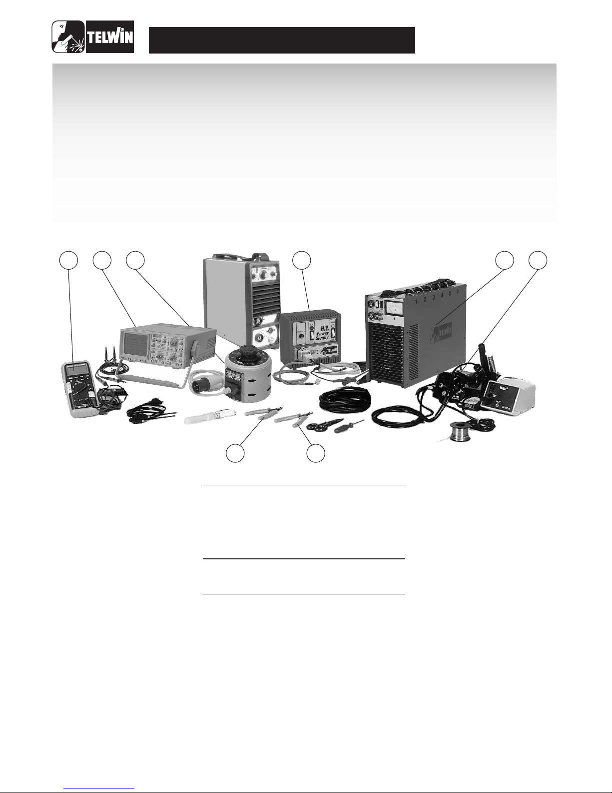
ESSENTIAL INSTRUMENTS
USEFUL INSTRUMENTS
MISCELLANEOUS
1 Oscilloscopio 20Mhz dual-trace cod. 802401
2 Static load generator cod. 802110
3 Variac 0 - 300v 1Kw cod. 802402
4 Power supply unit HV cod. 802403
5 Digital multimeter
6 Unwelding station
7 Flat-jaw pincers
8 Cutting nippers
(*)
(*)
(*)
(*)
Dismantling the inverter (see fig. 8)
A) Ensure that the power supply cable is disconnected from the mains..
B) Unscrew the 12 screws located at the four corners of the two blak plastic shells.
C) Slide out firstly the upper shell and then the lower shell.
D) Unscrew the two screws located below the wording "Technology TIG 165 "on the inverter side panel (13 , 14).
E) Slide out the casing by gently pulling it upwards.
F) Once you have completed the repair, proceed in reverse order to re-fit the casing and the shells, ensuring that the fold on the
upper part of the shell is fitted inside the frame and the lower part of the side walls is fitted outside the frame.
(*) The instruments with codes can be supplied by TELWIN. Sale price on request.

3
TECHNOLOGY TIG
1) Clean and visually check the
inverter
2) Checking the power and signal
cables.
3) Electrical measurements while the
machine is off.
Open the inverter shell and clean thoroughly using
compressed air.
Dirt is dangerous mainly in the power areas of the inverter
which are subject to high voltage or for those components
galvanically separating the primary from the secondary.
Thus, check carefully the following components:
Clean and check whether on the primary coil there are cuts or
cracks which could jeopardize the insulation of the secondary.
(Tig 165 DC/HF version.).
code 112478
(Tig 165 DC/HF version)
with high silicone insulation which connect the
H.F. transformer to the filter board and from the filter board to
the inverter shunt. (Tig 165 DC/HF 165 version.)
Check whether on the power transformer T1 or near
connector Jp1 there are signs of burns.
Visually check the post-gas and the gradual decreasing
of current potentiometers, the 2-4 phases electrode
and relays k1, k2.
These components must NOT have signs of dents, in
particular, the rotation of the potentiometers shaft
must be perfect and free from mechanical slacks.
(see Technology Repairs Manual)
(see Technology Repairs Manual)
( seeTechnology Repairs Manual )
(see Technology Repairs Manual)
check the cables fasten on connectors
J1, J2, J3. Specifically, check carefully the wires of connector
Jp1 in that there are subject to alternating network voltage.
check Cn01, Cn02, Fs01, Fs02
(See Technology Repairs Manual.)
1) H.F.Transformer:
2) H.F. Filter
3) H.F. Box
4) Electrovalve
5) Check cables
(See figure 2.)
A)
B)
7) Primary board:
8) Secondary board:
(See Figure 3-5)
1) Primary board:
2) Secondary board:
3) Tig control board:
4) Filter board:
(see Figure 2).
cod. 1124886) Control board Tig:
4) Electrical measurements while the
machine is in operation.
1)
(see figure 2).
2)
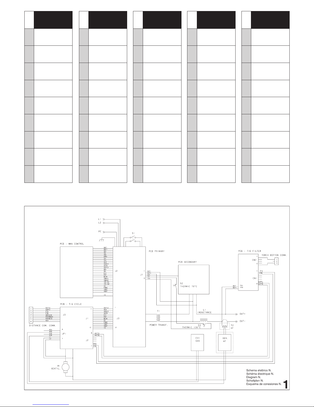
(See Figure 1.)
3)
4)
Warning!
the technology 114187 primary board cannot be mounted
on this machine.
5)
6)
- Jp1 Connector
- J2 Connector
- J1 Connector
7) Checking the operation of H.F. filter board, code 112478.
8) Checking the operation of tig control board, code 112488.
Disconnect the power supply cables of H.F. Box
Shortcircuit Jp2 on the primary board by means of a jumper
(placed between the SMD board and the electrolytic
condensers.
Remove all connectors from the tig control board. The inverter
is now set to work as a technology 165 with the switch located
on the front panel, in a central position ("hard welding").
Now follow the repair and test procedures of the inverter,
keeping in mind the following information:
1) the yellow led is not present on the board
2) the inverter carries the arc force and hod start functions.
Although the repair and test procedure are similar,
Remove the shortcircuit from Jp2 and put the connectors,
which were previously taken off from the tig control board, in
their places.
Switch the inverter on and check the following power supplies
on the tig control board:
Tester set in Vac
1) Place test prods on pins 1, 2 and you should have
220 Vac */- 10%
Tester set in Vac
Place test prods on pins 7, 8 and you should have 9
Vac +/- 10%.
1) Place negative test prod on pin 2 (mass) and
positive test prod on pin 1. The voltage should be +12
V +/- 3%.
2) Place negative test prod on pin 2 and positive test
prod on pin 3. The voltage should be -12 V +/- 3%.
- Ensure that the trimmer of pre-gas R 64 is rotated
counterclockwise.
Insert the tig torch and set the tig at two phases, press the torch
push-button. The electrovalve should be excited and, after a
short delay, the high frequency should be excited too. If this does
not happen, shortcircuit pins 1, 2 on connector J2.
If both the electrovalve and the high frequency are excited, it
means that there a failure on the filter board, probably due to the
following components:
a) Bridge rectifier P01.
b) Relay Rl 1
c) The alternating voltage 9 V on connector Cn 01 pin 7,
8 is missing.
d)The wire on the torch is cut off.
A J4 jumper is mounted on this board (see Figure 3), which
allows you to select two operation modes:
precedentemente tolti dalla scheda controllo tig.
Guide to repair of the inverter Tig

TECHNOLOGY TIG
4
R53) is properly set, the welding arc should strike.
b) Release the torch push-button, check the gradual
decreasing of current and the post-gas potentiometers.
a) Set the switch located on the front panel at 4-phase
position ( ).
b) Bring the tugsteno electrode in contact with the element to
be welded, press and release the torch push-button then lift
the electrode for about 2 mm; the welding arc should strike.
In order to obtain a gradual decreasing of current, you must
press and release the torch push-button for the second
time.Finally, check whether there is a post-gas.
Switch the remote control on (code 802109) and ensure that it
works correctly.
Warning! The following remote control adjusts the current in
function of the current set on the front panel; thus, if we set a
value of 50 A on the inverter, we could adjust this value from 5
A to 50 A by acting on the remote control.
Switch the "tig pulse" box on (code 802320) and ensure that
it works correctly by checking the current parameters relative
to peak, pause and work phases.
If striking a welding arc by means of high frequency proves to be
difficult (weak high frequency), the failure could be due to the
following components:
-Torch
- High frequency box
- High frequency transformer
- High frequency filter
- Primary coil with inverted polarity
If after having replaced these components the failure persists, we
suggest to check carefully the high frequency silicone insulated
cable as well as the high frequency transformer connection on the
positive inverter, which must NOT touch the carpentry or the wire
of the torch push-button. Furthermore, we suggest you
disassemble the positive dinse plug and check for signs of
discharges due to high frequency.
There are two types of tig control board and high frequency
transformers:
Tig control board
High frequency transformer
- The two tig control boards are perfectly compatible insofar as the
tig 165 DC-HF is concerned (high frequency striking).The board
with code 112453 instead, cannot be mounted on tigs with lift
striking (tig 161 DC-LIFT).
- The high frequency transformer in Figure 8 is equipped with a
different mechanical fastening system thus, should you need to
make a replacement on a tig mounting a transformer like the one
in Figure 5, you must drill three new holes on the carpentry
3) Checking the 4-phase cycle.
Checking the remote control.
1)
2)
High frequency striking
(See Figure 4-5)
(See Figure 6-7)
(see
Figure 6).
5) Changes and Updates
Jumper set towards connectors J1, J2 (H),
high frequency striking (tig 165 DC-HF).
Jumper set towards pre-gas and lift trimmers (L),
"lift" striking (tig 161 DC-LIFT).
Ensure that the aforementioned jumper is in H position.
Set the machine in electrode through the commutator.
Through static load or directly in welding, ensure the correct
operation of the inverter. (See "Final Testing" in Paragraph 5 of
the Technologic Repairs Manual.)
Set the inverter up for tig welding. (Connect torch and
argon gas bottle.)
Set the switch at two phases ( ) down slope and post-
gas potentiometers at the middle of the scale, the pre-
gas trimmer at the minimum (the trimmer is inside the
board).
Press the torch push-button:
The high frequency and the gas electrovalve should excite.
If after two seconds the welding arc does not strike, the
high frequency will automatically disexcite. On the other
hand, if the arc strikes, the current should reach the
value of about 80 A; when releasing the torch push-
button the current decreases gradually for about 2-3
seconds. From this time on, the electrovalve remains
excited for about 3 seconds.
Repeat the same testing procedure, however turning the pre-
gas trimmer clockwise and setting it at the maximum. By
pressing the torch push-button, the electrovalve will excite
but the high frequency will set off after a 4-second delay.
Set this trimmer as to have a 2-second delay or
according to the customer's needs.
Set the commutator at 4 phases ( ).
Repeat the preceding testing procedures, keeping in mind
that, in order to strike the arc you must press the torch push-
button.When releasing it, the welding current will remain at
the preset value (80 A).If the operator presses and releases
the torch push-button for a second time, the gradual
decreasing of current and the post-gas phases will begin.
Bring the electrode in contact with the element to be welded; if
you do not press the torch push-button, the yellow led
(D26) located on the front panel should switch on.
Set the welding current of the post-gas and the gradual decreasing
of current potentiometers as you did for the two-phase cycle.
A) Set the switch on front panel at two-phase( ) bring the
tugsteno electrode in contact with the element to be
welded, the led located on the front panel will switch on,
press the torch push-button. Through the plier-shaped
amperometer connected to the mass cable, check whether
there is a flow of current of about 20 A +/- 3 A. Should you
need to reset this value, act on trimmer R53. (In this phase,
the yellow led is switched off.)
a) Bring the tugsten electrode in contact with the element to
be welded, press the torch push-button and lift the
electrode by about 2 mm. If the lift current (20 A trimmer
A)
B)
1)
2)
3)
4)
A) Checking the Tig 165 DC/HF machine cycle
1)
2)
3)
4)
5)
B) Checking the Tig 161 DC-LIFT machine cycle
1) Checking the lift current:
2) Checking lift striking and the 2-phase cycle.
TECHNOLOGY TIG
5
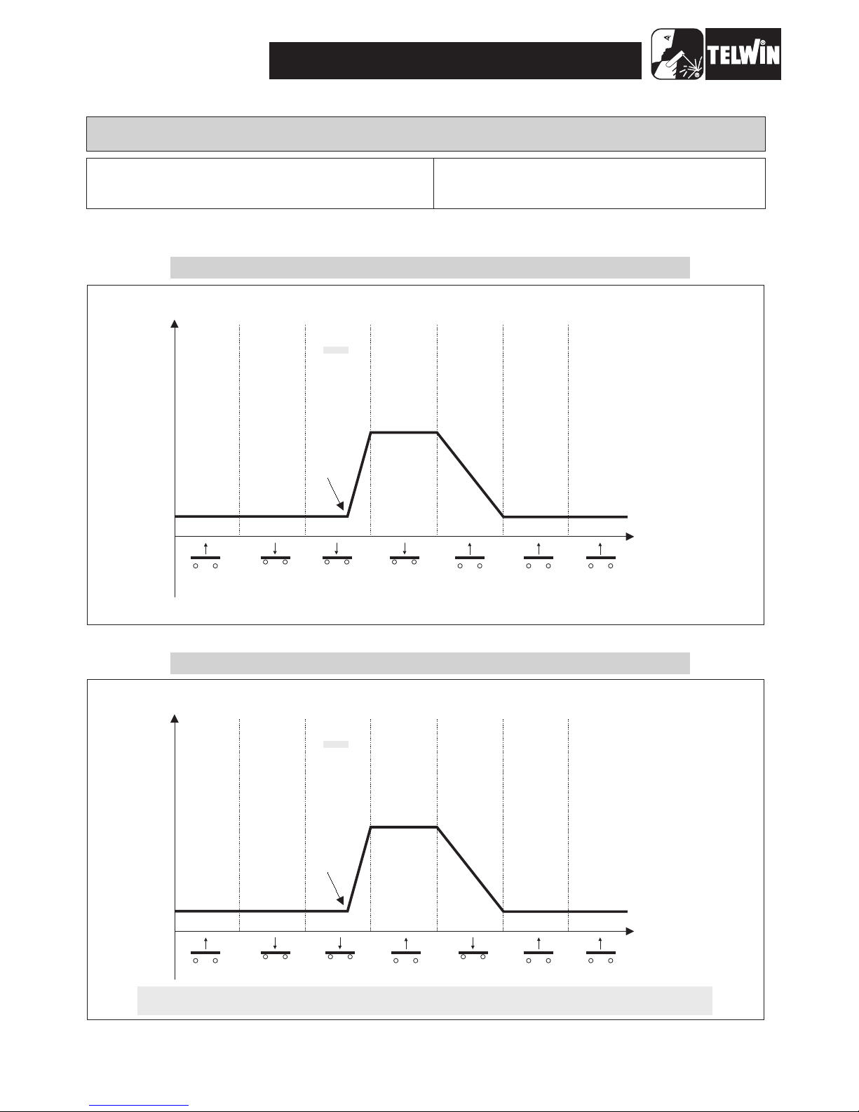
TWO-PHASE MACHINE CYCLE AT HIGH FREQUENCY
I
O
PRE GAS STRIKING
WELDING CURRENT
DOWN SLOPE POST GAS END OF CYCLE
EV= OFF
HF=OFF
I=Ø
EV= ON
HF= OFF
I=0
EV= ON
HF= ON
ARC
ARC STRIKING
EV= ON
HF= OFF
EV= ON
HF= OFF
EV= ON
HF= OFF
I=0
EV= OFF
HF= OFF
I=0
P.T. OFF P. T. ON P. T. ON P.T. ON P. T. OFF
P.T. OFF P. T. OFF
I
O
EV= OFF
HF=OFF
I=Ø
EV= ON
HF= OFF
I=0
EV= ON
HF= ON
ARC
EV= ON
HF= OFF
EV= ON
HF= OFF
EV= ON
HF= OFF
I=0
EV= OFF
HF= OFF
I=0
P.T. OFF P. T. OFF
P.T. OFF P. T. ON P. T. ON P.T. OFF P. T. ON
LEGEND
EV =Electrovalve
HF =High frequency
I=Welding current
D26 =Yellow led located on Tig front
D26: This led will switch on when between the electrode and the element to be welded there is direct current
thus stopping the inverter operation.
FOUR-PHASE MACHINE CYCLE AT HIGH FREQUENCY
PRE GAS STRIKING
WELDING CURRENT
DOWN SLOPE POST GAS END OF CYCLE
ARC STRIKING

TECHNOLOGY TIG
6
I
O
EV= OFF EV= ON EV= ON EV= ON EV= ON EV= ON EV= OFF
P.T. OFF P. T. ON P. T. ON P.T. ON P. T. OFF
P.T. OFF P. T. OFF
D26 ON D26 ON D26 OFFD26 OFF D26 OFF D26 OFFD26 OFF
I=0 I=0 I=0 I=0I=20A
TWO-PHASE MACHINE CYCLE LIFT STRIKING
I
O
EV= OFF EV= ON EV= ON EV= ON EV= ON EV= OFF
P.T. OFF P. T. ON P. T. OFF P.T. OFF
P.T. ON P. T. OFF
D26 ON D26 ON D26 OFFD26 OFF D26 OFF D26 OFFD26 OFF
I=0 I=0 I=0 I=0I=20A
P.T. ON
MINIMUM
TIME
PRE GAS
TRIMMER
R54
POST GAS
POTENTIOMETER
R58
DOWN SLOPE
POTENTIOMETER
R59
LIFT CURRENT
R53
CURRENT
MINIMUM (A)
CURRENT
MAXIMUM (A)
@0
@0
@0
@0
@45
@11
@8
@40
EV= ON
(s) (s)
PRE GAS STRIKING
WELDING CURRENT
DOWN SLOPE POST GAS END OF CYCLE
PRE GAS STRIKING
WELDING CURRENT
DOWN SLOPE POST GAS END OF CYCLE
FOUR-PHASE MACHINE CYCLE LIFT STRIKING
MAXIMUM
TIME

TECHNOLOGY TIG
7
Illustrated references
Jumper P 2
J1
J2
J3
Post-gas
(R58)
Yellow led
(D26)
Main current
supply
MMA Selector
2/4 Phases
Down
slope
(R59) Relay
k1,k2 JP 1
Figure n° 1
Remote control
connector
Figure n° 2
Cn 01
HF Filter
Fs 01
Supply cable
HF Box
HF Box
Primary plug
HF Silicone Cable
Positive
dinse
plug
Torch push-button
connector
HF Transformer
Fs 02
Cn 02
Electrovalve
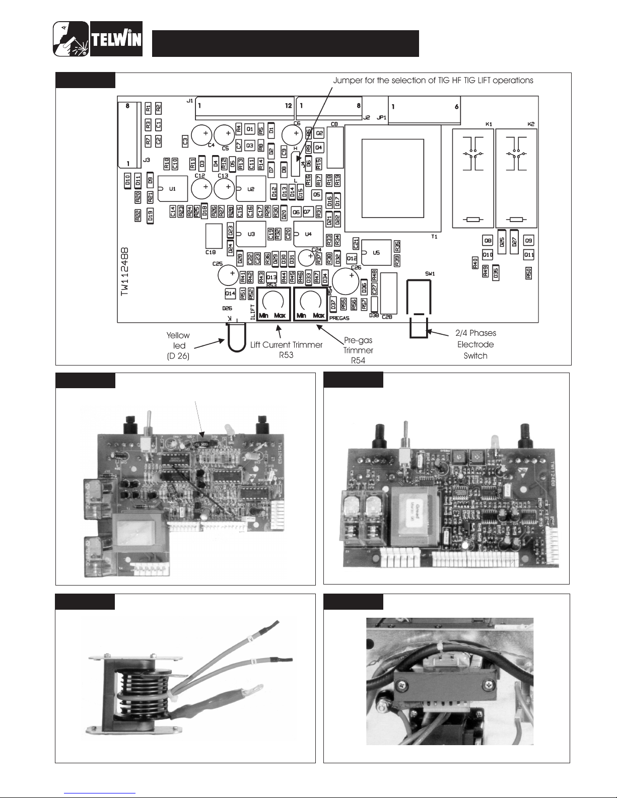
Figura n° 2
Figure n° 3
Figura n° 2
Figure n° 4 Figure n° 5
PRE-GAS
TRIMMER
Figura n° 2
Figure n° 6 Figura n° 2
Figure n° 7
TECHNOLOGY TIG
8

9
ELENCO PEZZI DI RICAMBIO - LISTE PIECES DETACHEES
SPARE PARTS LIST - ERSATZTEILLISTE
PIEZAS DE REPUESTO
Per richiedere i pezzi di ricambio senza codice precisare: codice della saldatrice; il numero di matricola; numero di riferimento del particolare sull'elenco ricambi.
Pour avoir les pieces detachees, dont manque la reference, il faudra preciser: modele, logo et tension de I'appareil; denomination de la piece; numero de matricule
When requesting spare parts without any reference, pls specify: model-brand and voltage of machine; list reference number of the item; registration number
Wenn Sie einen Ersatzteil, der ohne Artikel Nummer ist, benoetigen, bestimmen Sie bitte Folgendes: Modell-zeichen und Spannung des Geraetes; Teilliste Nuemmer; Registriernummer
Por pedir una pieza de repuesto sin referencia precisar: modelo-marca e tension de la maquina; numero di riferimento de lista; numero di matricula
Esploso macchina, Dessin appareil, Machine drawing, Explosionszeichnung des Geräts, Diseño seccionado maquina.
22
1
8
2
26
27
23
11
34
14
28
24
12 21 7 3330 3 6 18 4 29 16
201913 5 1025 35173032 9 15
10
(I) XX
(F) XX
(GB) XX
(D) XX
(E) XX
Per individuare lo schema elettrico corrispondente alla vostra macchina, rifarsi all'ultima cifra "/ " del numero di matricola (N. 0000/ ) riportato sul frontale.
Pour reperer le schema electrique correspondant a votre appareil, verifier le dernier chiffre"/ " du numero de serie (N. 0000/ ) reporte sur la partie frontale.
In order to find the electrical diagram corresponding to your model, check the last number "/ " of the serial number (N. 0000/ ) printed on front panel.
Um den schaltplan, der ihrem gerät entspricht, ausmachen zu können, müssen sie die letzte ziffer "/ " der matrikelnummer (N. 0000/ ), die auf der frontseite angebracht ist, beachten.
Para la identificacion del esquema eléctrico, correspondienten, a su máquina, refierase a la última cifra "/ " del número de placa (N. 0000/ ) instalado sobre el frontal.
REF. REF. REF. REF. REF.
ELENCO PEZZI DI RICAMBIO
PIECES DETACHEES
SPARE PARTS LIST
ERSATZTEILLISTE
PIEZAS DE REPUESTO
ELENCO PEZZI DI RICAMBIO
PIECES DETACHEES
SPARE PARTS LIST
ERSATZTEILLISTE
PIEZAS DE REPUESTO
ELENCO PEZZI DI RICAMBIO
PIECES DETACHEES
SPARE PARTS LIST
ERSATZTEILLISTE
PIEZAS DE REPUESTO
ELENCO PEZZI DI RICAMBIO
PIECES DETACHEES
SPARE PARTS LIST
ERSATZTEILLISTE
PIEZAS DE REPUESTO
ELENCO PEZZI DI RICAMBIO
PIECES DETACHEES
SPARE PARTS LIST
ERSATZTEILLISTE
PIEZAS DE REPUESTO
Potenziometro
Potentiometre
Potentiometer
Potenziometer
Potenciometro
Potenziometro
Potentiometre
Potentiometer
Potenziometer
Potenciometro
Rele'
Relais
Relais
Relais
Relais
Raddrizzatore Monofase
Redresseur Monophase
Single-phase Rectifier
Einphasiger Gleichrichter
Rectificador Monofasico
Scheda Filtro
Platine Filtre
Filter Card
Filterkarte
Tarjeta Filtro
Resistenza
Resistance
Resistor
Wiederstand
Resistencia
Condensatore
Condensateur
Capacitor
Kondensator
Capacitor
Manopola
Poignee
Knob
Knopf
Manija
Generatore H.f.
Generateur H.f.
H.f. Generator
H.f. Generator
Generador H.f.
Elettrovalvola
Electrovanne
Electrovalve
Elektroventil
Elektrovalvula
Deviatore
Gareur
Switch
Schalter
Interruptor
Interruttore
Interrupteur
Switch
Schalter
Interruptor
Termostato 10,0A
Thermostat 10,0A
Thermal Switch 10,0A
Thermostat 10,0A
Termostato 10,0A
Cablaggio Presa
Prise Cablee
Socket Wiring
Steckdose Mit Kabel
Cableado Enchufe
Assieme Condensatore
Condensateur
Capacitor Assembly
Kondensatorsatz
Grupo Capacitor
Cavo Alimentazione
Cable De Reseau
Mains Cable
Netzkabel
Cable De Alimentation
Motoventilatore
Ventilateur
Fan
Ventilator
Ventilador
Trasformatore Di Corrente
Transformateur De Courant
Current Transformer
Stromwandler
Transformador De Corriente
Trasformatore H.f.
Transformateur H.f.
H.f. Transformer
H.f. Transformator
Transformador H.f.
Assieme Trasformatore
Transformateur
Transformer Assy
Transformatorsatz
Grupo Transformador
Pressacavo
Presse Cable
Cable Bushing
Kabelhalter
Prensa Cable
Fibbia Per Cinghia
Boucle Pour Courroie
Belt Buckle
Gurtschnalle
Hebilla Para Correa
Cinghia
Courroie
Belt
Gurt
Correa
Cornice
Cadre
Frame
Rahmen
Marco
Fondalino
Chassis
Bottom
Bodenteil
Base
Mantello
Capot
Top Cover
Gehaeusedeckel
Tapa
Presa Dinse
Prise Dix
Dinse Socket
Dinse Steckdose
Enchufe Dinse
Raccordo Entrata Gas
Raccord Entree Gaz
Gas Pipe Connector
Gaseintritt
Racor Entrada Gas
Kit Igbt
Kit Igbt
Kit Igbt
Kit Igbt
Kit Igbt
Kit Diodo
Kit Diode
Kit Diode
Kit Diode
Kit Diodo
Kit Scheda Controllo Tig
Kit Platine De Control Tig
Tig Control Pcb Kit
Wig Steurungskarte Kit
Kit Tarjeta De Controlo Tig
Kit Scheda Secondario
Kit Fiche Secondaire
Kit Secondary Pcb
Kit Sekundaertrafokarte
Kit Tarjeta Secundario
Kit Scheda Primario
Kit Fiche Primaire
Kit Primary Pcb
Kit Primaertrafokarte
Kit Tarjeta Primario
Manopola Piccola
Poignee Petite
Small Knob
Kleiner Griff
Manija Pequena
Presa
Fiche
Plug
Stecker
Espina
1
2
3
4
5
6
7
8
9
10
11
12
13
14
15
16
17
18
19
20
21
22
23
24
25
26
27
28
29
30
31
32
33
34
35

TECHNOLOGY TIG
11
Official servicing centers
Repairing card
Date:
odel :
Serial number:
Company:
Technician:
Inverter m
In which place has the inverter been used domanda:
Building yard
Workshop
Others:
Supply:
Power suply
From mains without extension
From mains with extension m:
Mechanichal stresses the machine has undergone to
Description:
Dirty grade.
Dirty inside the machine
Description:
Kind of failure Component ref.
Substitution of primary circuit board: yes no
Troubles evinced during repair:
Rectifier bridges
Electrolytic capacitors
Relays
Pre-charge resistor
Snubber networks
Secondary diodes
Potentiometer
Potentiometer
IGBT
TECHNICAL REPAIR CARD
In order to improve our service, each servicing centre is requested to fill in the technical card above at the end
of every repair job.
Please fill in the card as accurately as possible and return in to Telwin.
Thank you in advance!

SINCERT
ACCREDITAMENTOORGANISMI CERTIFICAZIONE
SISTEMAQUALITA' CERTIFICATO
UNI EN ISO 9001
TGA-ZQ-002/92-00
Deutscher
Akkreditierungs
atR
CERTIFIED QUALITY SYSTEM
ISO
9001
TELWIN S.p.A.
800 801
- Via della Tecnica, 3
36030 VILLAVERLA (Vicenza) Italy
Tel. +39 - 0445 - 858811
Fax +39 - 0445 - 858 / 858
Table of contents
Other Telwin Inverter manuals


Popular Inverter manuals by other brands


Maxeon
Maxeon Sunpower E Series Safety and installation instructions

ABB
ABB UNO-DM-3.3-TL-PLUS-US-Q Quick installation guide

Giandel
Giandel PS-4000QAR user manual

Kaco
Kaco blueplanet gridsave 50.0TL3-S Series manual

Hitachi
Hitachi L200 Series Quick reference guide

Black & Decker
Black & Decker PI100BB instruction manual

Sunerg Solar Energy
Sunerg Solar Energy TENDAEVO 1T installation manual

Gallagher
Gallagher i Series manual

Parkside
Parkside PS 2900 A1 Translation of the original instructions

Hitachi
Hitachi J300 Series instruction manual

Siemens
Siemens SINAMICS G120P operating instructions

Analytic Systems
Analytic Systems IPSi2400-40-220 Installation & operation manual