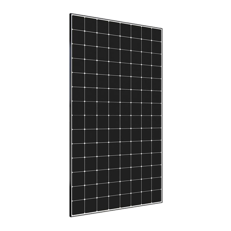
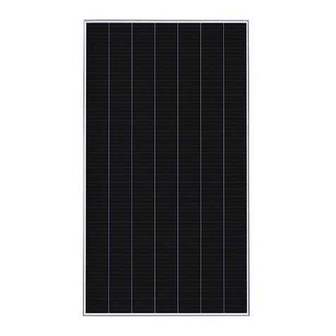
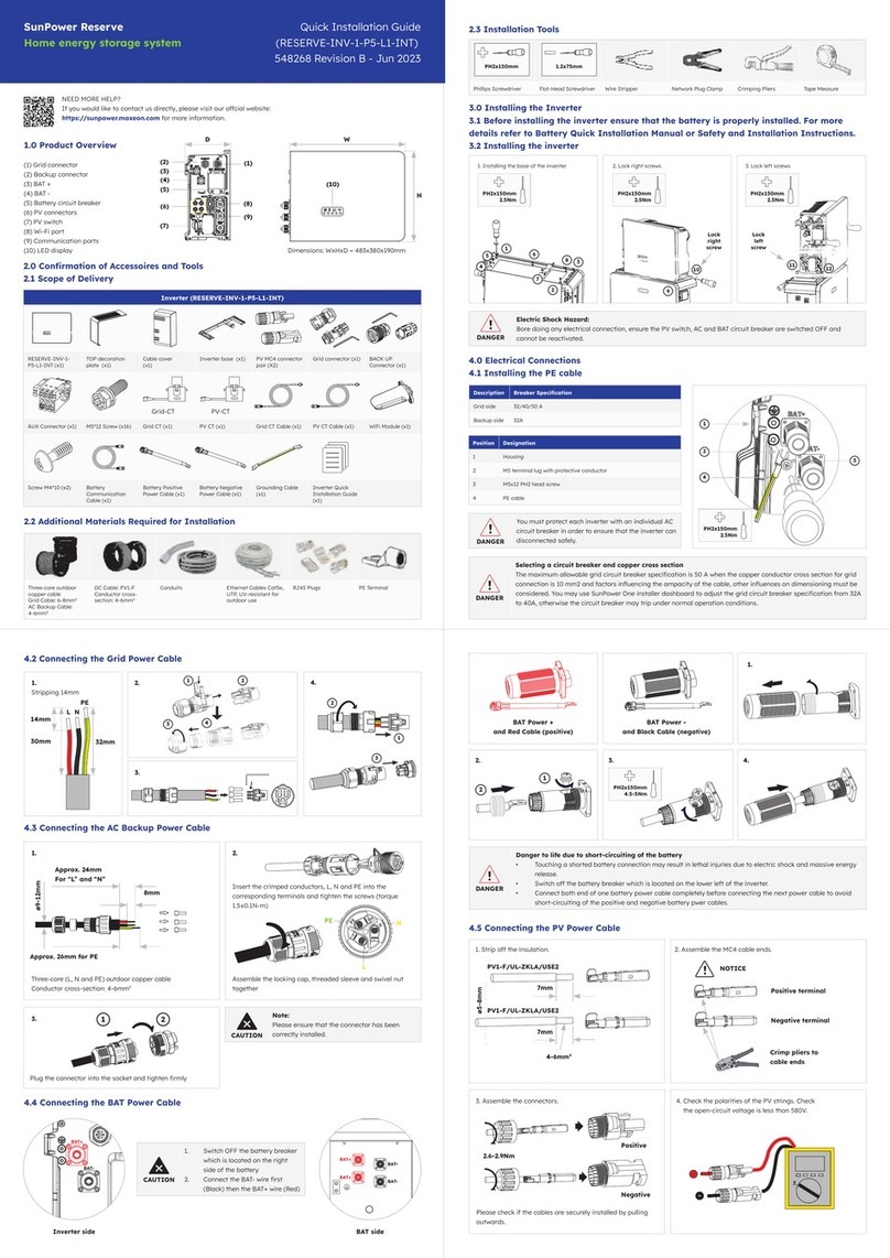
manuals.online logo
Brands
  1. Home
  2. •
  3. Brands
  4. •
  5. Maxeon
  6. •
  7. Inverter
  8. •
  9. Maxeon Sunpower E Series Setup guide

Maxeon Sunpower E Series Setup guide














SafetyandInstallationInstructions

forEurope,Asia,Australia,LatinAmericaandAfrica

ThisdocumentappliestoMaxeonPVModules

Languages:

English
French
German
Italian
Japanese
Spanish
Polish

Contentsofthismanualaresubjecttochangewithoutnotice.

IncaseofinconsistenciesorconflictsbetweentheEnglishversionandanyotherversionsofthismanual(or
document),theEnglishversionshallprevailandtakecontrolinallrespects.

ForthelatestEurope,Asia,Australia,LatinAmericaandAfricapleasereferto
www.sunpower.maxeon.com/int/PVInstallGuideIEC



MaxeonSolarTechnologies,Ltd.
www.sunpower.maxeon.com
Document001‐15497RevX
P/N100657
P/N520728
NEW REVISION: X
EnglishFrenchGermanItalianPolish 日本語
Spanish
MAXEONSOLARTECHNOLOGIES,LTD.
SafetyandInstallationInstructions‐Document001‐15497Rev.X
©June2022MaxeonSolarTechnologies,Ltd.Allrightsreserved.Specificationsincludedinthismanualaresubjecttochangewithoutnotice.
SafetyandInstallationInstructions
(English‐IECversion)

1.0 Introduction
ThismanualprovidessafetyandinstallationinstructionsforIEC
certifiedMaxeonphotovoltaicmodulescarryingtheTUVlogoonthe
productlabel(Figure1).

Figure1



1.1DisclaimerofLiability
Theinstallationtechniques,handlinganduseofthisproductare
beyondcompanycontrol.Therefore,Maxeondoesnotassume
responsibilityforloss,damageorexpenseresultingfromimproper
installation,handlingoruse.

1.2ConformitytoInternationalElectrotechnicalCommission(IEC)
standards
ThisproductmeetsorexceedstherequirementssetforthbyIEC
61215Edition3‐2016forPVModules,aswellasIEC61730Edition1
and2seriesforClassIIapplications.TheIECStandardcoversflat‐plate
PVmodulesintendedforinstallationonbuildingsandthoseintended
tobefreestanding.Thisproductisnotintendedforusewhere
artificiallyconcentratedsunlightisappliedtothemodule.
Thismanualshallbeusedincombinationwithindustryrecognized
bestpractices.Modulesshouldbeinstalledbycertifiedprofessionals
only.

1.3LimitedWarranty
ModulelimitedwarrantiesaredescribedintheMaxeonwarranty
documentobtainableatwww.sunpower.maxeon.com.Pleaseread
thisdocumentformoreinformation.
Warrantiesdonotapplytoanyofthefollowing;
PVModulessubjectedto:(i)misuse,abuse,neglectoraccident;
(ii)alterationorimproperinstallation(improperinstallation
includes,withoutlimitation,installationorarraythatdoesnot
complywithallMaxeoninstallationinstructionsandoperations
andmaintenanceinstructionsofanytype(asmaybeamended
andupdatedfromtimetotimeatMaxeon’ssolediscretion),and
allnational,state,andlocallaws,codes,ordinances,and
regulations);(iii)repairormodificationbysomeoneotherthan
anapprovedservicetechnicianofMaxeon;(iv)conditions
exceedingthevoltage,wind,snowloadspecifications;andany
otheroperationalspecification;(v)powerfailuresurges,
lightning,flood,orfire;(vi)damagefrompersons,biological
activity,orindustrialchemicalexposure;(vii)glassbreakagefrom
impactorothereventsoutsideMaxeon’scontrol.
2.0 SafetyPrecautions
Beforeinstallingthisdevice,readallsafetyinstructionsinthismanual.


CoverallmodulesinthePVarraywithanopaqueclothormaterial
beforemakingorbreakingelectricalconnections.
Donotdisconnectanymoduleswhenitsinverterisfeedinginto
thegrid.Switchofftheinverterbeforedisconnecting,reinstalling
ormakinganyactionwiththemodules.
Forconnectors,whichareaccessibletountrainedpeople,itis
imperativetousethelockingconnectorsandsafetyclips,if
applicable,inordertodefendagainstuntrainedpersonnel
disconnectingthemodulesoncetheyhavebeeninstalled.
Allinstallationsmustbeperformedincompliancewithall
applicableregionalandlocalcodes.
Therearenouserserviceablepartswithinthemodule.Donot
attempttorepairanypartofthemodule.
Installationshouldbeperformedonlybyqualifiedpersonnel.
Removeallmetallicjewelrypriortoinstallingthisproductto
reducethechanceofaccidentalexposuretolivecircuits.
Useinsulatedtoolstoreduceyourriskofelectricshock.
Donotstandon,walk,drop,andscratchorallowobjectstofallon
theglasssurfaceofthemodules.
Damagedmodules(brokenglass,tornbacksheet,brokenj‐boxes,
brokenconnectors,etc)canbeelectricalhazardsaswellas
lacerationhazards.Contactwithdamagedmodulesurfacesor
moduleframecancauseelectricshock.Damagedmodulesshould
beimmediatelydisconnectedfromtheelectricsystem.The
moduleshouldberemovedfromarrayassoonaspossibleand
contactthesupplierfordisposalinstructions.
Unconnectedconnectorsmustalwaysbeprotectedfrompollution
(e.gdust,humidity,foreignparticles,etc),priortoinstallation.Do
notleaveunconnected(unprotected)connectorsexposedtothe
environment.Acleanassemblyenvironmentisthereforeessential
toavoidperformancedegradation.
Donotallowtheconnectorstocomeincontactwithchemicals
suchasgreases,oilsandorganicsolventswhichmaycausestress
cracking.
Donotinstallorhandlethemoduleswhentheyarewetorduring
periodsofhighwind.
Donotblockdrainholesorallowwatertopoolinornearmodule
frames
Contactyourmodulesupplierifmaintenanceisnecessary.
Savetheseinstructions!
3.0 ElectricalCharacteristics
ThemoduleelectricalratingsaremeasuredunderStandardTest
Conditions(STC)of1kW/m²irradiancewithAM1.5spectrumanda
celltemperatureof25°C.Maxeonmoduleshavespecificelectrical
characteristicsasshownonthedatasheets.
Aphotovoltaicmodulemayproducemorecurrentand/orvoltage
thanreportedatSTC.Sunny,coolweatherandreflectionfromsnow
orwatercanincreasecurrentandpoweroutput.Therefore,thevalues
ThisdocumentincludesreferencestoMaxeonE‐series(SPR‐Eyy‐
xxx),X‐series(SPR‐Xyy‐xxx),P‐Series(SPR‐Pyy‐xxx,SPR‐P3‐xxx,
SPR‐Py‐xxx‐UPP,SPR‐Py‐xxx‐COM‐M‐BF,SPR‐Py‐xxx‐COM‐S‐BF,
SPR‐Py‐xxx‐BLK,SPR‐Py‐xxx‐COM‐XS),SPR‐MAX2‐xxx,SPR‐MAX3‐
xxx,SPR‐MAX5‐xxx,SPR‐MAX6‐xxxPVModules.
DonotmixE,X,MAX2,MAX3,MAX5,MAX6,PSeries,P3,P5and
P6inoneSystem.
Allmoduleseriesdoesnotrequirefunctionalgroundingandare
compatiblewithtransformer‐lessinverters(ref.section4.1)
Important!Pleasereadthisinstructionsheetinitsentirety
beforeinstalling,wiring,orusingthisproductinanyway.
Failuretocomplywiththeseinstructionswillinvalidatethe
MaxeonLimitedWarrantyforPVModules.
Danger!Moduleinterconnectspassdirectcurrent(DC)andare
sourcesofvoltagewhenthemoduleisunderloadandwhenitis
exposedtolight.Directcurrentcanarcacrossgapsandmay
causeinjuryordeathifimproperconnectionordisconnectionis
made,orifcontactismadewithmodulecomponentsthatare
damaged.Donotconnectordisconnectmoduleswhencurrent
fromthemodulesoranexternalsourceispresent.
MAXEONSOLARTECHNOLOGIES,LTD.
SafetyandInstallationInstructions‐Document001‐15497Rev.X
©June2022MaxeonSolarTechnologies,Ltd.Allrightsreserved.Specificationsincludedinthismanualaresubjecttochangewithoutnotice.
ofIscandVocmarkedonthemoduleshouldbemultipliedbyafactor
of1.25whendeterminingcomponentvoltageratings,conductor
ampacities,fusesizes,andsizeofcontrolsconnectedtoPVoutput.An
additional1.25multipliermayberequiredbycertainlocalcodesfor
sizingfusesandconductors.Maxeonrecommendstheuseofopen‐
circuitvoltagetemperaturecoefficientslistedonthedatasheetswhen
determiningMaximumSystemVoltage.
4.0 ElectricalConnections
Modulesmaybeconnectedinseriesand/orparalleltoachievethe
desiredelectricaloutputaslongascertainconditionsaremet.Please
useonlythesametypeofmodulesinacombinedsourcecircuit.

Evenifallowedbylocalregulation,PlugandSocketconnectorsmated
togetherinaPVsystemmustbeofthesametype(model,rating)from
thesamemanufactureri.e.aplugconnectorfromonemanufacturer
andasocketconnectorfromanothermanufacturer,orviceversa,
shallnotbeusedtomakeaconnection.Maxeonrecommendsthatall
wiringbedoubleinsulatedwithaminimumratingof85°C(185°F).All
wiringshoulduseflexiblecopper(Cu)conductors.Theminimumsize
shouldbedeterminedbytheapplicablecodes.Werecommendasize
notlessthan4mm2.Theinsulationtypeshouldbeappropriateforthe
typeofinstallationmethodusedandmustmeetSCII(SafetyClassII)
andIEC61730requirements.Tominimizetheriskfromindirect
lightningstrikes(Voltagesurges),thesystemshouldbedesignedto
avoidloopsinthewiring.
Maxeonrecommendsaconservativeminimumbendingradius(R)5x
cablediametermustbemaintainedandmustnotbebentonthe
directexitoftheconnectororjunctionbox.Avoidexposureof
electricalconnectionstodirectsunlightanddonotplacethe
connectorinalocationwherewatercouldeasilyaccumulate.
Installersmustrefertoconnectormanufacturer’sinstructionfor
furtherinstallationandconnectionrequirements.
Connectorsarefactoryassembledwithintentionalgapsbetweenthe
cablenutandthebodyoftheconnector.Donotretightenmodule
connectornutsasthismayleadtostresscrackingoftheconnector
assemblyandwillvoidthewarranty.

4.1System&EquipmentGrounding
Pleaserefertotheapplicableregionalandlocalcodesongrounding
PVarraysandmountingframesforspecificrequirements(e.g.
lightningprotection).

ModuleTypes
SPRE,X,PseriesmodulesandourMaxeonandPerformanceProductLine
arecompatiblewithTransformerLess(TL)inverters,whenusedasan
ungroundedPVsource.
Noframegroundingrequirements(includingfunctionalframegrounding),
butmaybesubjectedtolocalregulation.
Functionalsystemgroundingofapolarity(positiveornegative)isoptional
andmaybesubjecttolocalrequirements.
ESeries:
SPR‐Eyy‐xxxSPR‐Eyy‐xxx‐BLKSPR‐Eyy‐xxx‐COM
XSeries:
SPR‐Xyy‐xxxSPR‐Xyy‐xxx‐BLKSPR‐Xyy‐xxx‐COM
PSeries/PerformanceProductLine:
SPR‐Pyy‐xxx‐COMSPR‐Pyy‐xxxSPR‐Pyy‐xxx‐BLKSPR‐P3‐xxx‐COM
SPR‐P3‐xxx‐COM‐1500SPR‐P3‐xxxSPR‐P3‐xxx‐BLKSPR‐P5‐xxx‐UPP
SPR‐P6‐xxx‐COM‐M‐BFSPR‐P6‐xxx‐COM‐S‐BFSPR‐P6‐xxx‐BLKSPR‐
P6‐xxx‐COM‐XS
MaxeonProductLine:
SPR‐MAX2‐xxxSPR‐MAX2‐xxx‐COM
SPR‐MAX3‐xxxSPR‐MAX3‐xxx‐BLKSPR‐MAX3‐xxx‐COMSPR‐MAX5‐
xxx‐COMSPR‐MAX6‐xxxSPR‐MAX6‐xxx‐BLK,SPR‐MAX6‐xxx‐COM
Note:IfyouareinstallinganolderModuleTypethanabove
mentioned,pleaserefertodifferent/previousapplicableSafetyand
InstallationManual.
Ifyouaredoingaframegroundingconnection,avoidthedirect
contactbetweenAluminumandCopperusinganintermediatemetal
likestainlesssteelortin.

4.2SeriesConnection
Themodulesmaybewiredinseriestoproducethedesiredvoltage
output.Donotexceedthemaximumsystemvoltagespecifiedin
moduledatasheet.
4.3ParallelConnection
Themodulesmaybecombinedinparalleltoproducethedesired
currentoutput.Seriesstringmustbefusedpriortocombiningwith
otherstringsiftheresultingmaximumreversecurrentexceedsthe
fuseratingasshowninthedatasheets.Bypassdiodesarefactory
installedinthemodules.Pleaserefertotheapplicableregionaland
localcodesforadditionalfusingrequirementsandlimitationsonthe
maximumnumberofmodulesinparallel.
5.0 ModuleMounting
TheMaxeonLimitedWarrantyforPVModulesiscontingentupon
modulesbeingmountedinaccordancewiththerequirements
describedinthissection.

5.1SiteConsiderations
Maxeonmodulesshouldbemountedinlocationsthatmeetthe
followingrequirements:
OperatingTemperature:AllMaxeonmodulesmustbemountedin
environmentswithinthefollowingmaximumandminimumoperating
temperatures:
MaximumOperatingTemperature +85°C(+185°F)
MinimumOperatingTemperature ‐40°C(‐40°F)
Careshouldbetakentoprovideadequateventilationbehindthe
modules,especiallyinhotenvironments.

Shading:Modulesshouldbeinstalledsothatpermanentshadingof
cellsisavoidedandpartialshadingthatmayoccurduringcertain
timesofthedayoryearisminimized.Permanentshadingisdefined
asshadethatiscastoverthesameposition(ofconstantarea)ofthe
solarmodulethroughoutthegenerationhoursoftheday.
Shadingmayinduceincertaincasesstrongenergyproduction
reduction,evenincaseofsmallshadingandshouldbeavoidasmuch
aspossible,speciallyatmid‐daywhentheproductionismaximum.

DesignStrength:Maxeonmodulesaredesignedtomeetapositiveor
negative(upwardanddownward,e.g.wind)withstandingtest
pressureloadandanegative(ordownward,e.g.staticloadorsnow
load)withstandingtestpressureload,asperIEC61215,when
mountedintheconfigurationsspecifiedinSection5.2andTables1.2
or1.3below.

Whenmountingmodulesinsnowproneorhighwindenvironments,
specialcareshouldbetakentomountthemodulesinamannerthat
providessufficientdesignstrengthwhilemeetinglocalcode
requirements.

AdditionalauthorizedOperatingEnvironments:
Modulescanbemountedinthefollowingaggressiveenvironment
accordingtothetestlimitsmentionedbelow(availableuponrequest)
Saltmistcorrosiontesting:IEC61701Severity6
AmmoniaCorrosionResistance:IEC62716Concentration:6,667ppm


English
MAXEONSOLARTECHNOLOGIES,LTD.
SafetyandInstallationInstructions‐Document001‐15497Rev.X
©June2022MaxeonSolarTechnologies,Ltd.Allrightsreserved.Specificationsincludedinthismanualaresubjecttochangewithoutnotice.
ExcludedOperatingEnvironments:
Certainoperatingenvironmentsarenotrecommendedforspecific
MaxeonmodulesandareexcludedfromtheMaxeonLimited
Warrantyforthesemodules.
NoMaxeonmoduleshouldbemountedatasitewhereitmaybe
subjecttodirectcontactwithsaltwater,orotheraggressive
environment.
Modulesshouldnotbeinstallednearflammableliquids,gases,or
locationswithhazardousmaterials;ormovingvehiculesofanytype.

PerformanceSeriesMountingOrientation
PerformanceSeries(P‐Series)modulesaredesignedtobeinstalledin
landscapeorientation.Inlandscapeorientation,P‐seriesmodules
maintainhigherpowerunderrowtorowshadingandedgesoiling.

5.2MountingConfigurations

Mountingsystemmustprovideaflatplaneforthemodulestobe
mountedonandmustnotcauseanytwistorstresstobeplacedon
theModule,evenincaseofthermalexpension.

Modulesmaybemountedatanyanglefromhorizontaltovertical.
Selecttheappropriateorientationtomaximizesunlightexposure.
Maxeonrecommendsforagoodperformanceofthesystem
(reductionofsoilingeffect/waterpooling)aminimumof5˚tiltangle.
Thecleaningfrequencymustbeincreasedformodulesinstalledwith
averylowangle.
Commercialmodules(96&128cells)frameshavepermanently
attachedstackingpinslocateda20mmzoneonthelongsideframeat
388‐408mm(“D”areainFigure2).Mountingsystemhardwareused
withcommercialmodulesmustaccountforthepresenceofthese
stackingpins(seeTable2).

Specificinformationonmoduledimensionsandthelocationof
mountingandgroundingholesisprovidedinFigures2andTable2.

Inordertopreventwaterfromenteringthejunctionbox,whichcould
presentasafetyhazard,modulesshouldnotbemountedsuchthat
thefront/topglassfacesdownward(e.g.,onatrackingstructurethat
positionsthemodulewiththejunctionboxfacingskywardduring
sleepmode).

Wealsowanttoremindthatthewatertightnessisnotensuredbythe
modulesbutbythemountingsystemandthatdrainageshouldbewell
designedforModules.

Clearancebetweenthemoduleframesandstructureorgroundis
requiredtopreventwiringdamageandallowsairtocirculatebehind
themodule.Therecommendedassemblingclearancebetween
modulesinstalledonanymountingsystemisaminimumof5mm
distance.
Wheninstalledonaroof,themoduleshallbemountedaccordingto
thelocalandregionalbuildingandfiresafetyregulations.Incasethe
moduleisinstalledinaroofintegratedPV‐System(BIPV),itshallbe
mountedoverawatertightandfire‐resistantunderlaymentratedfor
suchapplication

Modulesmountingsystemsshouldonlybeinstalledonbuildingthat
havebeenformallyconsideredforstructuralintegrity,andconfirmed
tobecapableofhandlingtheadditionalweightedloadoftheModules
andmountingsystems,byacertifiedbuildingspecialistorengineer.

Mountingsystemsuppliershallmanagethegalvaniccorrosionwhich
canoccurbetweenthealuminiumframeoftheModulesand
mountingsystemorgroundinghardwareifsuchdevicesiscomprised
ofdissimilarmetals.
Themoduleisonlycertifiedforusewhenitsfactoryframeisfully
intact.Donotremoveoralterthemoduleframe.Creatingadditional
mountingholesorremovingthestackingpinsmaydamagethe
moduleandreducethestrengthoftheframe,thereforearenot
allowed.UsingmountingClampsorclipswithadditionalgrounding
boltsorgroundingmetalsheetscouldbeincompliancewiththis
SafetyandInstallationInstructionsmanualsubjecttoconditionsof
Section4.1
Modulesmaybemountedusingthefollowingmethodsonly:

1) FrameHoles:Securethemoduletothestructureusingthe
factorymountingholes.FourM6orM8stainlesssteelbolts,
withnuts,washers,andlockwashersarerecommendedper
module.Boltstobefastenaccordingtorackingsupplier
recommendations.RefertoTable2forthemoduledimensions
andmountingholelocations.(Pleaserefertothearrowsonthe
Table2,E1&E2&E3&E4).

2) PressureClampsorClips:Mountthemodulewiththeopposite
clipsonthelongerand/orshortersideoftheframeofthe
module.TheclipsallowedlocationshouldbeaccordingtoTable
1.1.Installersshouldensuretheclampsareofsufficient
strengthtoallowforthemaximumdesignpressureofthe
module.ClipsandclampsarenotprovidedbyMaxeon.Clamps
mustapplyforcecollinearwiththe‘wall’ofthemoduleframe
andnotonlytothetopflange.Clampsshallnotapplyexcessive
forcetothetopframe,warpthetopflange,orcontacttheglass‐
thesepracticesvoidthemodulewarrantyandriskglass
breakage.Figure1a
illustrateslocationsfortop
frameclampforce.Avoid
clampingwithin50mmof
modulecornerstoreduce
riskofframecorner
deflectionandglass
breakage.Whenclamping
tothemoduleframe,
torqueshouldneverexceed15N.mtoreducechancesofframe
deformation,iftheclampdatasheetsshowaspecifictorque
valuewhichislowerthan15Nmtheinstallershouldfollowthe
torquevaluewhicheverismorestringent.Acalibratedtorque
wrenchmustbeused.Mountingsystemsshouldbeevaluated
forcompatibilitybeforeinstallingspeciallywhenthesystemis
notusingClampsorclips.PleasecontactMaxeonforthe
approvaloftheuseofnon‐standardpressureclampsorclips
wheretorquevaluesarehigherthanotherwisestated.

3) EndMount:Endmountingisthecapturemountingofthe
lengthofthemodule’sshorterframeswithclampsoneach
shortersidesoftheframe.Threedifferentconfigurationsare
possible:1)withtwomountingrailsunderthecompletelength
ofeachshortersideoftheModules,(SeeTable1.2),2)withtwo
mountingrailsparalleltothelongsideoftheModules(See
Table1.2)and3)withoutanymountingrail(SeeTable1.2).The
end‐mountingrailsandclipsorclamps(identifiedasA
(1&2&3&4)

inTable1.1)mustbeofsufficientstrengthtoallowfor
maximumdesignedtestpressureofthemodule.Verifythis
capacitywiththemountingsystemofvendorbefore
installation.
4) HybridMount:Combinationwithclampsorclipslocatedon
longerorshortersidesofModulesarealsopossible,seeTable
1.2forallowedconfigurations.Inanycase,fourclampings
pointsareneeded.

Force must not deform
top frame flange or
glass may break
Force has
to be
applied in
line with
frame
wall
Fi
g
ure 1a: Clam
p
Force Locations
MAXEONSOLARTECHNOLOGIES,LTD.
SafetyandInstallationInstructions‐Document001‐15497Rev.X
©June2022MaxeonSolarTechnologies,Ltd.Allrightsreserved.Specificationsincludedinthismanualaresubjecttochangewithoutnotice.
5) MaxeonspecifiedorMaxeonsuppliedmountingsystems.
ModulesmountedwithstrictadherencetoMaxeon
documentation,usinghardwaresystemssuppliedbyor
specifiedbyMaxeon.

Figure2andTable1.1belowdemonstratethemountinglocationsand
Tables1.2and1.3giveallowedloadratings(designedtestvalue)for
Maxeonmodules.
Figure2:MountingZonelocationsforMaxeonmodules 
ForP‐Series,MAX396,104,112cellsandMAX666cells:

For128cells,P‐SeriesandMAX5/MAX6Commercial:


Table1.1:Approvedmoduleclamping/directfixationzones
ModuleConfigurationMountingzonedistancefrom
cornerin(mm)1
Frame
holes
E
Modulesize
Frame
type
ABC
(1&2&3&4)(1&2&3&4)(1&2&3&4)(1&2&3&4)
96cells,104
cells(MAX2,
MAX3),112
cells,P3BLK
andP3RES+
G3
(Black)
Silver&
G4.1&
G4.2&
G4.3
50‐350

150‐380

50‐150


Asper
Drawingin
theTable2
128cellsand
P19‐COM
G4&
G4.1&
G4.2
50‐350408‐88050‐375
P3‐COMG4.2&
G4.350‐350408‐83350‐375
MAX6(66cells)G5.250‐350265‐51450‐265
MAX5and
MAX6COM
(72cells)
G4.2&
G5.650‐350296‐53650‐296
D‐Thereisa20mmzoneat388‐408mmfromthecornerwheremountingisnot
allowedduetothemodulestackingpinfeature.Applicableto128and96cell
commercialonly.
1) Nopartofthemoduleclampmayextendbeyondthisarea.




Figure3:MountingConfigurations
Configurations1and2showmountingwithrailsupport,3and4
showmountingwithoutrailsupport.In“WithRailSupport”therails
becomesconventionalorrailstransversewhile“WithoutRail
Support”becomesendmountedinlongorshortside.Inthecase
whentheglassdeflectsitwouldnotdeflectintherailsforadditional
support.
Table1.2:MountingZoneDesignLoadRatingsforRackingsystem
withoutrailsupportunderneaththemodule.Refertoconfiguration
3and4inFig.3
Module
Configuration
Wind(up&down)/Snow(down)
(unitsinPa)(***)
Module
size
Frame
type
End
Mount
A
(1&2&3&4)
Frame
Holes
E
(1&2&3&4)
B
(1&2&3&4)
C(1&2&3&4)
orB+C
(B1&3+C2&4orB2&4+C1&3)
OrA+B
(A1&3+B2&4orA2&4+B1&3)
OrA+C
(A1&3+C2&4orA2&4+C1&3)
96cells,
andP3BLK
G3
Black&
Silver&
G4.1&
G4.2&
G4.3

2400/
2400(*)

2400/
5400


2400/
5400


2400/2400

104cells
(MAX2,
MAX3)and
112‐cells
(MAX3)
G4.21800/
1800
P3RES+G4.31300/
1600
1600/
2400
1600/
2400
1300/
1600
128cells,
P19‐COM
G4&
G4.1&
G4.2
Not
applicable
(**)
2400/
5400
3600/
36002400/2400
P3‐COMG4.2&
G4.3
1600/
1600
1600/
2400
1600/
24001600/1600
MAX6(66
cells)G5.21600/
1600
3600/
3600
3600/
36001600/1600
MAX5‐
COM
(72cells)
G4.2 1600/
16003600/
3600
3600/
36001600/1600
MAX6‐
COM
(72cells)
G5.61067/
1200
(*):5400Paisallowedwithclampsandmountingrailsalongthelongersideoftheframe
(**):2400/2400Paareallowedwithclampsandmountingrailsalongthelongersideof
theframe
ForRooftopapplication1200/1200Paisallowedwithonlyclamps
(***)Safetyfactorof1.5included










MAXEONSOLARTECHNOLOGIES,LTD.
SafetyandInstallationInstructions‐Document001‐15497Rev.X
©June2022MaxeonSolarTechnologies,Ltd.Allrightsreserved.Specificationsincludedinthismanualaresubjecttochangewithoutnotice.
Table1.3:MountingZoneLoadRatingsforRackingsystemwithrail
support.RefertoConfiguration1and2inFig.3
ModuleConfiguration
Wind(up&down)/
Snow(down)
(unitsinPa)(***)
ModulesizeFrametypeB(1&2&3&4)C(1&2&3&4)
96cellsandP3BLKG3(Black&Silver)&
G4.1&G4.2 2400/5400
2400/2400
104cells(MAX2,
MAX3)and112‐cells
(MAX3)
G4.23600/5400
P3RES+G4.31600/36001600/3600
128cellsandP19‐COMG4&G4.1&G4.23600/54002400/3600
P3‐COMG4.2&G4.32000/24001600/2400
MAX6(66cells)G5.23600/60002800/2800
MAX5andMAX6COM
(72cells)G4.2&G5.63000/54002400/2400

Table1.4:MountingZoneLoadRatingsforPerformanceModules
Applicable
Products2
Mounting
Zone
Distance
from
corner
(mm)
Wind(up&
down)/
Snow(down)
(unitsinPa)3
Mounting
Method
P3UPP
(2066x1160x
35mm)

A183‐2831600/2400
Clamp

B466‐5661600/36004
C783‐8331600/1600
D260‐3201600/1600
E465‐5651600/2400
Frame
Holes2
383(1300)1600/1600
Bolt
504(1058)1600/3600
683(700)1600/1600
833(400)
P5UPP&
P6COM‐
M
(2384x1092x
35mm)
A442‐5421600/3600
Clamp6
B546‐6921600/36004
C967‐10171160/1160
D243‐303800/1600Clamp7
E546‐6921600/3600Clamp8
1600/2000Clamp9
F50‐1501200/1200Clamp9
Frame
Holes2
492(1400)1600/3600
Bolt5
642(1100)1600/3600
992(400)1160/1160
P6RES
BLK
(1808x1086x
30mm)
A50‐1001200/1300
Clamp6
B402‐5021600/3600
C654‐754800/1300
D221‐3211066/1066Clamp7
E402‐5021200/1800Clamp8
F50‐1001300/1300Clamp9
P6COM‐S
(2185x1092x
35mm)
A50‐1001066/1200
Clamp6
B496‐5961600/3600
C842‐9421066/1600
D223‐323933/1600Clamp7
F50‐1001066/1200Clamp9
Frame
Holes2
1100(392)1600/3600Bolt
1400(542)1600/3600
2RefertoTable2fordifferentmountingholelocations
3SafetyFactor1.5included
4IECvalidated
5Minimumwashersizeof24mmindiameterisrequired.
6LongSideMounting,RailsPerpendiculartoMountingFrame
7ShortSideMounting,RailsParalleltoMountingFrame
8LongSideMounting,RailsParalleltoMountingFrame
9LongSideMounting,PointSupported





Figure4:MountingZoneLocationsforPerformancemodules
ForP3,P5UPPandP6(COM‐M,COM‐S,RESBLK)


5.3GroundMountApplicationsforBifacialmodules
Variousenvironmentalandinstallationparametersaffectbifacial
gain.Albedoisameasureoftheamountoflightreflectedfromthe
groundsurface.Ahigheralbedofactorwillincreaseirradianceonthe
backsideandresultinhigherbifacialgainofthemodule.Thesurface
conditions,monthoftheyear,timeofday,GHIandDNIbothinfluence
theamountofincidentrearsideirradiance.
Maxeonrecommendstocheckwithsolarmodulemountinghardware
supplierinordertodeterminetheStructureShadingfactorofyour
particularinstallation.TheStructureShadingFactorvarieswith
rackingsystemdesign,irradiance,albedoandheightofmodule
installationabovegroundandhasanoverallimpactontherearside
irradiancemismatch.

TheRearsidemismatchlossesareproportionaltothealbedo,height
ofthemodulesabovegroundandstructureshadingfactor.The
irradiancenon‐uniformityontherearsideresultsinmismatch
generallyasthealbedoincreasesandinstallationheightofthe
modulesarelowertotheground.

5.4RooftopApplicationsforBifacialmodules
Bifacialmodulesusedirect,reflectedordiffusesunlightatthe
rearsidetogenerateadditionalpower.Therefore,itisrecommended
tousebifacialmodulesinstalledonflatroofapplications.

Inordertomaximizethebifacialgainattherooftopapplicationsthe
followingparameterslistedbelowshouldbeconsidered:
•SurfaceAlbedo
•RoofIntegrity
•ModuleTiltAngle
•ModuleElevation
•StructuralBacksideShading

Thebifacialmodulescanbemountedbothlandscapeorportrait
orientation.
MAXEONSOLARTECHNOLOGIES,LTD.
SafetyandInstallationInstructions‐Document001‐15497Rev.X
©June2022MaxeonSolarTechnologies,Ltd.Allrightsreserved.Specificationsincludedinthismanualaresubjecttochangewithoutnotice.
Wheninstallingabifacialmoduleonaroof,checkapplicablebuilding
codesandensurethattheroofconstructionandthestructuralload
calculationsofthebuildingaresuitable.
Bifacialgaintendstobemosteffectivewithahighertiltangle.
Asthetiltangleandthemoduleelevationfromtheunderlyingsurface
increases,morereflectedlightanddiffuselightcanbecapturedbythe
module.Themountingrailsshallbedesignedtolimittherearside
shadingasmuchaspossible.Obstaclesbetweenmodulesandthe
groundshouldbeavoidedasmuchaspossibleinordertoincreasethe
bifacialgain.

5.5BifacialElectricalConsiderations
Theoverallelectricalbifacialgainisdeterminedbythecombinationof
surfacealbedo,irradiance,moduletiltangle,shadinglossesfromthe
rearside,rearsidemismatchandmoduleelevationaboveground.
PleaserefertotheMaxeondatasheetfortheelectricaloutputswith
respecttotheoverallbifacialgain.Pleaseutiliseasuitable
performancesoftwarepackagetosimulatetheoverallbifacialgain.

5.6HandlingofModulesduringInstallation
Donotplacemodulesfaceforwardindirectcontactwithabrasive
surfaceslikeroofs,driveways,woodenpallets,railings,stuccowalls,
etc…
Themodulefrontsurfaceglassissensitivetooilsandabrasive
surfaces,whichmayleadtoscratchesandirregularsoiling.
Duringstorage,modulesneedtobeprotectedfromrainoranykinds
ofliquids.Requiredstoragetemperatureisbetween10°Cto40°Cina
dryenvironment(humiditybetween30to80%).Donotstoremodules
outdoortoavoidmoistureandwetconditions.

Modulesthatfeatureantireflectivecoatedglassarepronetovisible
fingerprintmarksiftouchedonthefrontglasssurface.Maxeon
recommendshandingmoduleswithanti‐reflectiveglasswithgloves
(noleathergloves)orlimitingtouchingofthefrontsurface.Anyfinger
printmarksresultingfrominstallationwillnaturallydisappearover
timeorcanbereducedbyfollowingthewashingguidelinesinSection
6.0below.Anymodulecoverage(coloredplastictarpsorsimilar)
duringinstallationcanleadtopermanentfrontglassdiscolorationand
isnotrecommended.Theuseofvacuumliftingpadscancause
permanentmarksonthefrontglass.Neverliftormovethemodule
usingthecablesorthejunctionboxunderany‐circumstances.
ShadingincidenceneedtobeavoidedduringPVsystemoperation.
Thesystemisnotsupposedtobeenergizeduntilthemounting
scaffolding,fencesorrailinghavebeenremovedfromtheroof.
Systemsshouldbedisconnectedinanycasesofmaintenancewhich
cancauseshading(e.g.chimneysweeping,anyroofmaintenance,
antenna/dishinstallations,etc).
6.0Maintenance
Maxeonrecommendsvisualinspectiononaregularbasisofall
modulesforsafeelectricalconnections,soundmechanical
connection,andfreefromcorrosion.Thisvisualinspectionshouldbe
performedbytrainedpersonnel.Thestandardfrequencyisoncea
yearaccordingtoenvironmentalconditions,periodiccleaningof
modulesisrecommendedbutisnotrequired.Periodiccleaninghas
resultedinimprovedperformancelevels,especiallyinregionswith
lowlevelsofannualprecipitation(lessthan46,3cm(18,25inches)).
Consultyourdealerorsupplieraboutrecommendedcleaning
schedulesforyourarea.

Tocleanamodule,washwithpotable,non‐heated,water.Normal
waterpressureismorethanadequate,butpressurizedwaterupto
100bar(min.50cmdistance)maybeused.Maxeonrecommends
usingalargehosepipeandnottoperformcleaningathighoutside
temperatures.Fingerprints,stains,oraccumulationsofdirtonthe
frontsurfacemayberemovedasfollows:firstrinseoffareaandlet
soakforashortperiodoftime(5mins).Re‐wetanduseasoftsponge
orseamlessclothtowipeglasssurfaceinacircularmotion.

Fingerprintstypicallycanberemovedwithasoftclothorspongeand
waterafterwetting.Donotuseharshcleaningmaterialssuchas
scouringpowder,steelwool,scrapers,blades,orothersharp
instrumentstocleantheglasssurfaceofthemodule.Useofsuch
materialsorcleaningwithoutconsultationwillinvalidatetheproduct
warranty.AsdrycleaningisalsoriskyforAnti‐Reflective(AR)coated
modulesurface,spinningbrushisnotrecommendedformodule
cleaning.








MAXEONSOLARTECHNOLOGIES,LTD.
SafetyandInstallationInstructions‐Document001‐15497Rev.X
©June2022MaxeonSolarTechnologies,Ltd.Allrightsreserved.Specificationsincludedinthismanualaresubjecttochangewithoutnotice.
Table2:ModuleFrameDetails


PlatformModulemountingandgroundholedetailFrameProfile
RESIDENTIALG3FRAMEONLY
Residential
Modules
96CELLMODULEFRAMEDETAILSIDEFRAMEPROFILE


ENDFRAMEPROFILE

FORCOMMERCIAL(SILVERFRAME)MODULESONLY,INCLUDESSTACKINGPINS
Commercial
Modules

96CELLCOMMERCIALMODULE128CELLCOMMERCIALMODULESIDEFRAMEPROFILE



WithStackingPins
ENDFRAMEPROFILE

32 mm
46.08 mm
10.30 mm
18.50 mm
2.20 mm
22 mm
46.08 mm
10.50 mm
1.27 mm
4X Ø 4.8 mm
Drain Holes
12X Ø 6.6 mm
Mounting Holes
6X Ø 4.2 mm
Ground Holes
4X Ø 6.10 mm
Stackings Pins
3.2 mm
398 mm
46 mm
(Back View)
(Front View)
Stacking Pins
4X Ø6.10 mm
300 mm
20X Ø6.8 mm
Mounting Holes
4X Ø4.2 mm
Ground Holes
4X Ø4.8 mm
Drain Holes
398 mm
3,2 mm 46 mm
(Front View)
(Back View)
1046 mm
1002 mm
2067 mm
1200 mm
1423 mm
539 mm
32 mm
46.08 mm
3.18 mm 10.30 mm
18.50 mm
2.20 mm
22 mm
46.08 mm
10.50 mm
1.27 mm
Method 1:
Frame Hole
Locations
Method 1:
Frame Hole
Locations
MeasurementTolerancesare+/‐3mmfortheLengthandWidthoftheModule.
MAXEONSOLARTECHNOLOGIES,LTD.
SafetyandInstallationInstructions‐Document001‐15497Rev.X
©June2022MaxeonSolarTechnologies,Ltd.Allrightsreserved.Specificationsincludedinthismanualaresubjecttochangewithoutnotice.


PlatformModulemountingandgroundholedetailFrameProfile
FORP‐SERIESCOMMERCIALGEN4.1FRAMEMODULES
Commercial
Modules


SIDEFRAMEPROFILE

ENDFRAMEPROFILE

FORP‐SERIESCOMMERCIALGEN4.2FRAMEMODULES
Commercial
Modules


SIDEFRAMEPROFILE
ENDFRAMEPROFILE

FOR104cGEN4.2FRAMEMODULES
Commercial
Modules

SIDEFRAMEPROFILE
ENDFRAMEPROFILE
998 mm
46 mm
MODEL:SPR-P19-410-COM
RatedPower(Pmax)
1
(+5/ 0
%) 410 W
Voltage(Vmp) 43.9
V
Current(Imp) 9.35
A
Open-CircuitVoltage(Voc) 53.1
V
Short-CircuitCurrent(Isc) 9.94
A
MaximumSeriesFuse 15
A
1
StandardTestConditions:1000W/m
2
,AM1.5,25°C
Suitableforungrounded,positive,or negative grounded DC systems
FieldWiring:Cuwiringonly, min. 12 AWG/4 mm
2
,insulatedfor90°C min.
WARNING
SEVEREELECTRICALHAZARD
•Solarmodulehas full voltage even in very low light.
•Installationshouldonly be done by a qualified technician.
527040
www.sunpower.com
Patentedasshownatwww.sunpower.com/patents
SafetyClassII
FireRating:ClassC
Max.SystemVoltage:1500VDC
954 mm
961 mm
2067 mm
300 mm
400 mm
539 mm
1058 mm
1200 mm
1423 mm
1606 mm
4X Ø 4.2mm
Ground Holes
20X Ø 6.8mm
Mounting Holes 4X 5.0mm (W) x 15.0mm (L)
SLOT
46mm
32mm
46mm
24 mm
998 mm
40 mm
MODEL:SPR-P19-410-COM
RatedPower(Pmax)
1
(+5/ 0
%) 410 W
Voltage(Vmp) 43.9
V
Current(Imp) 9.35
A
Open-CircuitVoltage(Voc) 53.1
V
Short-CircuitCurrent(Isc) 9.94
A
MaximumSeriesFuse 15
A
1
StandardTestConditions:1000W/m
2
,AM1.5,25°C
Suitableforungrounded,positive,or negative grounded DC systems
FieldWiring:Cuwiringonly, min. 12 AWG/4 mm
2
,insulatedfor90°C min.
WARNING
SEVEREELECTRICALHAZARD
•Solarmodulehas full voltage even in very low light.
•Installationshouldonly be done by a qualified technician.
527040
www.sunpower.com
Patentedasshownatwww.sunpower.com/patents
SafetyClassII
FireRating:ClassC
Max.SystemVoltage:1500VDC
954 mm
961 mm
2067 mm
400 mm
539 mm
1058 mm
1200 mm
1423 mm
1606 mm
4X Ø 4.2mm
Ground Holes
18X Ø 6.8mm
Mounting Holes 4X 5.0mm (W) x 15.0mm (L)
SLOT
32mm
40 mm
24 mm
40 mm
4x Ø 4.2 mm
Ground Holes
8x Ø 6.8 mm
Mounting Holes
1690 mm
1500 mm
1300 mm
1100 mm
1046 mm
1002 mm
32mm
40 mm
24 mm
40 mm
MeasurementTolerancesare+/‐3mmfortheLengthandWidthoftheModule.
MAXEONSOLARTECHNOLOGIES,LTD.
SafetyandInstallationInstructions‐Document001‐15497Rev.X
©June2022MaxeonSolarTechnologies,Ltd.Allrightsreserved.Specificationsincludedinthismanualaresubjecttochangewithoutnotice.


PlatformModulemountingandgroundholedetail
FORP3MODULES
Residential/
Commercial
Modules
P3BLK(GEN4.3)P3COM(GEN4.2)

SIDEFRAMEPROFILEENDFRAMEPROFILESIDEFRAMEPROFILEENDFRAMEPROFILE

FORP3GEN4.3FRAMEMODULES
Commercial
Modules
P3UPPP3COM

SIDEFRAMEPROFILEENDFRAMEPROFILESIDEFRAMEPROFILE ENDFRAMEPROFILE


998 mm
954 mm
1690 mm
1300 mm
1100 mm
4X Ø4.2mm
Ground Holes
Mounting Holes
8X Ø6.8mm
400 mm
539 mm
1058 mm
1423 mm
954 mm
2066 mm
998 mm
40
4X Ø4.2mm
Ground Holes
Mounting Holes
12X Ø6.7mm
Mounting Holes
4X Ø6.8mm
4X 5.0mm (W)
x 15.0mm (L)
SLOT
1200 mm
1606 mm
32mm
35 mm
24 mm
35 mm
32mm
40 mm
24 mm
40 mm
1160 mm
2066 mm
MODEL:SPR-P19-410-COM
RatedPower(Pmax)
1
(+5/ 0
%) 410 W
Voltage(Vmp) 43.9
V
Current(Imp) 9.35
A
Open-CircuitVoltage(Voc) 53.1
V
Short-CircuitCurrent(Isc) 9.94
A
MaximumSeriesFuse 15
A
1
StandardTestConditions:1000W/m
2
,AM1.5,25°C
Suitableforungro unded, positive,ornegativegroundedDC systems
FieldWiring:Cuwiringonly, min. 12 AWG/4 mm
2
,insulatedfor90°C min.
WARNING
SEVEREELECTRICALHAZARD
•Solarmodulehasfull voltage even in very low light.
•Installationshouldonlybe done by a qualified technician.
527040
www.sunpower.com
Patentedasshownatwww.sunpower.com/patents
SafetyClassII
FireRating:ClassC
Max.SystemVoltage:1500VDC
400 mm
700 mm
1058 mm
1300 mm
4X Ø4.2 mm
Ground
Holes
8X 10mm(L) x 7mm(W)
R3.5mm
Mounting Holes
8X 14mm(L) x 9mm(W)
R4.5mm
SLOTS
35mm
400 mm
539 mm
1058 mm
1423 mm
954 mm
2066 mm
998 mm
35
4X Ø4.2 mm
Ground
Holes
Mounting Holes
4X Ø6.7 mm
Mounting Holes
12X Ø6.8 mm
4X 5.0 mm (W)
x 15.0 mm (L)
SLOTS
1200 mm
1606 mm
35 mm
35 mm
35 mm
35 mm
32mm
35 mm
24 mm
35 mm
MeasurementTolerancesare+/‐3mmfortheLengthandWidthoftheModule.
MAXEONSOLARTECHNOLOGIES,LTD.
SafetyandInstallationInstructions‐Document001‐15497Rev.X
©June2022MaxeonSolarTechnologies,Ltd.Allrightsreserved.Specificationsincludedinthismanualaresubjecttochangewithoutnotice.


PlatformModulemountingandgroundholedetailFrameProfile
FORP3UPPGEN4.3(Customized)
Commercial
Modules

SIDEFRAMEPROFILE

ENDFRAMEPROFILE

FORP5UPP&P6BIFACIALGEN4.3
Commercial
Modules

SIDEFRAMEPROFILE
ENDFRAMEPROFILE

FORMAX5GEN4.2MODULES
Commercial
Modules
 
SIDEFRAMEPROFILE
ENDFRAMEPROFILE
2066 mm
MODEL:SPR-P19-410-COM
RatedPower(Pmax)
1
(+5/ 0
%) 410 W
Voltage(Vmp) 43.9
V
Current(Imp) 9.35
A
Open-CircuitVoltage(Voc) 53.1
V
Short-CircuitCurrent(Isc) 9.94
A
MaximumSeriesFuse 15
A
1
StandardTestConditions:1000W/m
2
,AM1.5,25°C
Suitableforungrounded,positive,or negative grounded DC systems
FieldWiring:Cuwiringonly, min. 12 AWG/4 mm
2
,insulatedfor90°C min.
WARNING
SEVEREELECTRICALHAZARD
•Solarmodulehas full voltage even in very low light.
•Installationshouldonly be done by a qualified technician.
527040
www.sunpower.com
Patentedasshownatwww.sunpower.com/patents
SafetyClassII
FireRating:ClassC
Max.SystemVoltage:1500VDC
274 mm
1160 mm
4X Ø4.2 mm
Ground Holes
8X (14mmx9mm)
Mounting Holes
1118 mm
2022 mm
35 mm
35 mm
35 mm
35 mm
1092 mm
1043 mm
400 mm
1100 mm
1400 mm
2384 mm
4X Ø4.2mm
Ground Holes
8X 14mm (L) x 9mm (W)
R4.5mm
SLOTS
4X 10mm (L) x 7mm (W)
R3.5mm
Mounting Holes
35 mm
35 mm
35 mm
35 mm
16 mm
1935 mm
1423 mm
1200 mm
539 mm
400 mm
973 mm
980 mm
1058 mm
1999 mm
1016 mm
20x Ø6.8
Mounting Holes 4x Ø4.22
Ground Holes
4x 5mm(W) x 15mm (L)
SLOTS
32 mm
40 mm
24 mm
40 mm
MeasurementTolerancesare+/‐3mmfortheLengthandWidthoftheModule.
MAXEONSOLARTECHNOLOGIES,LTD.
SafetyandInstallationInstructions‐Document001‐15497Rev.X
©June2022MaxeonSolarTechnologies,Ltd.Allrightsreserved.Specificationsincludedinthismanualaresubjecttochangewithoutnotice.

PlatformModulemountingandgroundholedetailFrameProfile
FORP3RES+(GEN4.3)
Residential
Modules

SIDEFRAMEPROFILE

ENDFRAMEPROFILE

FOR112cGEN4.2FRAMEMODULES
Residential/
Commercial
Modules

SIDEFRAMEPROFILE
ENDFRAMEPROFILE

FORMAX666‐CELLGEN5.2FRAMEMODULES
Residential
Modules


SIDEFRAMEPROFILE

ENDFRAMEPROFILE

1100 mm
1300 mm
1500 mm
1690 mm
1160 mm
35 mm
4X Ø 4.2mm
Ground Holes
8X Ø 6.8 mm
Mounng Holes
35mm
32 mm
35mm
24 mm
4x Ø 4.22 mm
Grounding Holes
8x Ø 6.80 mm
Mounting Holes
1812 mm
1656 mm
1300 mm
1100 mm
1046 mm
1002 mm
32mm
40 mm
24 mm
40 mm
1872 mm
1032 mm
Ground Holes
40mm
Quarter Mount Holes
1100 mm
32 mm
40mm
24 mm
40mm
MeasurementTolerancesare+/‐3mmfortheLengthandWidthoftheModule.
MAXEONSOLARTECHNOLOGIES,LTD.
SafetyandInstallationInstructions‐Document001‐15497Rev.X
©June2022MaxeonSolarTechnologies,Ltd.Allrightsreserved.Specificationsincludedinthismanualaresubjecttochangewithoutnotice.

PlatformModulemountingandgroundholedetailFrameProfile
FORMAX672‐CELLGEN5.6FRAMEMODULES
Commercial
Modules

SIDEFRAMEPROFILE

ENDFRAMEPROFILE

FORP6COM‐SBIFACIALGEN4.3
Commercial
Modules

SIDEFRAMEPROFILE

ENDFRAMEPROFILE

FORP6RESBLACKGEN4.4
Residential
Modules

SIDEFRAMEPROFILE

ENDFRAMEPROFILE

35 mm
400 mm
1200 mm
1423 mm
1653 mm
1983 mm
2047 mm
1039 mm
995 mm
4X Ø 4.60mm
Ø 7.40mm X 90º
MLSD Holes
16X Ø 6.80 mm
Mounting Holes
4X Ø 4.22 mm
Ground Holes
60 mm
96.50 mm
32 mm
35 mm
32 mm
35 mm
35 mm
1092 mm
2185 mm
1100 mm
1400 mm
1051 mm
4X Ø4.2
Grounding Holes
8X 9mm (W) x 14mm (L), R4.5
Mounting Holes
35 mm
30 mm
35 mm
16 mm
30 mm
1086 mm
1808 mm
1100 mm
1038 mm
4X Ø4.2
Grounding Holes
4X 9mm (W) x 14mm (L), R4.5
Mounting Holes
30 mm
33 mm
30 mm
24 mm
MeasurementTolerancesare+/‐3mmfortheLengthandWidthoftheModule.

This manual suits for next models

15

Other Maxeon Inverter manuals

Maxeon SPR-P6-555-UPP User manual

Maxeon

Maxeon SPR-P6-555-UPP User manual

Maxeon SunPower Reserve User manual

Maxeon

Maxeon SunPower Reserve User manual

Maxeon SunPower Reserve User manual

Maxeon

Maxeon SunPower Reserve User manual

Maxeon SunPower Reserve Setup guide

Maxeon

Maxeon SunPower Reserve Setup guide

Maxeon Sunpower User manual

Maxeon

Maxeon Sunpower User manual

Popular Inverter manuals by other brands

Innova Filomuro SLW 400 Installation and user manual

Innova

Innova Filomuro SLW 400 Installation and user manual

TOYODenki VF66B operating manual

TOYODenki

TOYODenki VF66B operating manual

AIMS Power PRM1000W12120S Operation manual

AIMS Power

AIMS Power PRM1000W12120S Operation manual

ATD Tools ATD-5953 instruction manual

ATD Tools

ATD Tools ATD-5953 instruction manual

Mastervolt Whisper 6 user manual

Mastervolt

Mastervolt Whisper 6 user manual

Analytic Systems IPS600 SERIES Installation & operation manual

Analytic Systems

Analytic Systems IPS600 SERIES Installation & operation manual

enphase M250 Quick install guide

enphase

enphase M250 Quick install guide

Hitachi SJ100DN DeviceNet Series Addendum instruction manual

Hitachi

Hitachi SJ100DN DeviceNet Series Addendum instruction manual

Mosa GE 4500 HSX manual

Mosa

Mosa GE 4500 HSX manual

Morningstar SureSine 150 W Installation and operation manual

Morningstar

Morningstar SureSine 150 W Installation and operation manual

Fuling Inverter DZB200 Series user manual

Fuling Inverter

Fuling Inverter DZB200 Series user manual

SMA 9000TL user manual

SMA

SMA 9000TL user manual

SEW-Eurodrive MOVITRAC 07 operating instructions

SEW-Eurodrive

SEW-Eurodrive MOVITRAC 07 operating instructions

Telefunken TF-PI04 instruction manual

Telefunken

Telefunken TF-PI04 instruction manual

Generac Power Systems GUARDIAN QT060 Specfications

Generac Power Systems

Generac Power Systems GUARDIAN QT060 Specfications

AQUASTREAM ABSC02787 Installation, operation & maintenance manual

AQUASTREAM

AQUASTREAM ABSC02787 Installation, operation & maintenance manual

Sealey POWER PRODUCTS PI300 instructions

Sealey

Sealey POWER PRODUCTS PI300 instructions

SunSynk SUNSYNK-29.9K-SG01HP3-EU-BM3 Installer manual

SunSynk

SunSynk SUNSYNK-29.9K-SG01HP3-EU-BM3 Installer manual

manuals.online logo
manuals.online logoBrands
  • About & Mission
  • Contact us
  • Privacy Policy
  • Terms and Conditions

Copyright 2025 Manuals.Online. All Rights Reserved.