Telwin TECHNOLOGY TIG 172 Operating instructions

cod. 988647
inverter
TECHNOLOGY TIG 172
AC/DC - HF/LIFT
TROUBLESHOOTING
AND REPAIR MANUAL
TROUBLESHOOTING
AND REPAIR MANUAL
“reparation no problem !”
TROUBLESHOOTING
AND REPAIR MANUAL
TROUBLESHOOTING
AND REPAIR MANUAL
CONTENTS PAGE
OPERATION AND WIRING DIAGRAMS................ 2
REPAIR GUIDE.......................................................13
SPARE PARTS LIST...............................................26
REPAIR SHEET......................................................28
- Block diagram 2
- Analysis of the block diagram 3
- Illustrations 5
- Wiring diagrams 7
- Equipment required 13
- General repair instructions 14
- Troubleshooting and remedies 14
- Testing the machine 18
- Illustrations 21

15
TECHNOLOGY TIG 172 AC/DC
-2-
TIG & MMA
CYCLE CONTROL
31
678
245
1
13
17
33
11
3
23
29
32
30
34
12
19
V
t
16
20
PROTEZIONE
SOVRATENSIONE
V
t
14
IGBT DRIVER
21
SEPARAZIONE
GALVANICA
22
INDUCTANCE
THERMOSTAT
27
SCR DRIVER
25
SHUNT AMPLIFIER
+|
26
MAXIMUN
CURRENT REGOLATOR
18
CONTROL PANEL
24
10
+
-
9
AC/ DC CURRENT
CONVERTER
28
BLOCK DIAGRAM
OPERATION AND WIRING DIAGRAMSOPERATION AND WIRING DIAGRAMS
OPERATION AND WIRING DIAGRAMSOPERATION AND WIRING DIAGRAMS
HF TRANSFORMER
SHUNT INDUCTANCE
PRIMARY
EMC FILTER
POWER
TRANSFORMER
PRE-CHARGE
RECTIFIER BRIDGE FILTER CHOPPER
SECONDARY
DIODES
SECONDARY
EMC FILTER
CURRENT
TRANSFORMER
FAN POWER SUPPLY
LED
PRIMARY CURRENT
READER
MICROCONTROLLER
UNDERVOLTAGE
SAFEGUARD
DUTY CYCLE
MAKER
ADDER
TORCH BUTTON
SOLENOID VALVE
RELAY
HF GENERATOR
SOLENOID VALVE
TORCH BUTTON
RELAY
AUXILIARY
TRANSFORMER
SECONDARY
DIODE THERMOSTAT
OUTPUT
INPUT

-3-
ANALYSIS OFTHE BLOCK DIAGRAM
Block 1
Block 2
Block 4
Block 5
Block 6
Block 7
NOTE:Unless indicated otherwise, it should be assumed that
thecomponentsareassembledontheweldingmachine.
Consistingof:C3,C8,C9,L1 .
Preventsnoisefromthemachine frombeingtransmittedalong
themainpowerlineandviceversa.
Consistingof:D3,D5 .
Convertsthe mains alternating voltageinto continuous pulsed
voltage.
Consistingof:C2,C4,C5,C6,C7 .
Converts the pulsed voltage from the rectifier bridge into
continuousvoltage.
Consistingof:Q1,Q2 .
Converts the continuous voltage from the filter into a high
frequency square wave capable of piloting the power
transformer.
Regulates the power according to the required welding
current/voltage.
Consistingof:T2.
TheC.T.isusedtomeasurethecurrentcirculatinginthepower
transformer primary and transmit the information to block 14
(primarycurrentreaderandlimiter).
Consistingof:T1 .
Adjusts the voltage and current to values required for the
welding procedure. Also forms galvanic separation of the
primary from the secondary (welding circuit from the power
supplyline).
EMC Filter
Rectifier bridge
Filter
Chopper
Current transformer
Power transformer
(primaryboard)
(primaryboard)
Consistingof:K1,K2,R1(primaryboard).
Prevents the formation of high transient currents that could
damage the main switch, the rectifier bridge and the
electrolyticcapacitors.
When the power source is switched on relays K1 and K2 are
de-energised, capacitors C2, C4, C5, C6, C7 are therefore
charged via R1. When the capacitors are charged the relays
willbeenergised.
(primaryboard)
(primaryboard)
(primaryboard)
Consisting of: D1, D2, D3, D4, D5, D6, D7, D8, D9, D10
(secondaryboard)
D1, D2 convert the current circulating in the positive OUT of
the power transformer to a single direction, preventing
saturationofthenucleus.
D3, D4, D5 recirculate the inductance output current (block 9)
during the time when the IGBT's are not conducting,
bypassingthepowertransformer(block7).
Block 3
Block 8
Pre-charge
Secondary diodes
Positivepolaritydiodesinthecircuit:
Negativepolaritydiodesinthecircuit:
D9, D10 convert the current circulating in the negative OUT of
the power transformer to a single direction, preventing
saturationofthenucleus.
D6, D7, D8 recirculate the inductance output current (block 9)
duringthetimewhentheIGBT'sarenotconducting,bypassing
thepowertransformer(block7).
The positive polarity diodes in the circuit are
involved. The positive and negative polarity diodes in the
circuitareinvolvedalternately.
Consistingof:SCR(secondaryboard)
The SCR module is piloted by block 18 (microcontroller) and
block 27 (SCR driver), transforming the secondary output
currentfromDCtoACwhenTIGACweldingisrequired.
Consistingof:L1,R2,(secondaryboard)
The inductance levels the output current from the secondary
board diodes making it practically direct.The shunt detects
the current circulating in the secondary and sends a voltage
signal to block 25 (shunt amplifier), which will process it.
(primaryboard)
(primaryboard)
Consistingof:D16,R81,R82,R83,R84,R85(controlboard).
Detectsandlimitsthesignal from block6 (current transformer)
and, via trimmer R85, adjusts the maximum allowable primary
current. The signal is also redimensioned so that it can be
processedandcomparedinblock16(dutycyclemaker).
Consistingof:U14(controlboard).
Processes the information arriving from block 17 (adder) and
block 15 (primary current reader and limiter), producing a
square wave with variable duty cycle, limiting in any case the
primarycurrenttoamaximumpresetvalue.
DC Operation:
AC Operation
Block 9
Block 10
Block 15
Block 16
Primary current reader and limiter
Duty cycle maker
AC/DC current converter
Inductance and Shunt
Secondary EMC Filter
HF Transformer
Flyback power supply
IGBT Driver
Block 11
Block 12
Block 13
Block 14
Consistingof: CY1.
Prevents noise from the power source from being transmitted
throughtheweldingcablesandviceversa.
Consistingof:T2.
The HF transformer boosts the signal from block 34 (hf power
source), raising the voltage impulse in the secondary at the
instantwhenarcstrikeisgenerated.
Italsoisolatestheweldingcircuitfromtheprimarycircuit
Consistingof:T2,U2 .
Uses switching methods to transform and stabilise the voltage
obtained from block 4 (filter) and supplies auxiliary voltage to
powerblock14(driver)andthecontrolboardcorrectly.
Consistingof:ISO1,ISO2 ..
Takes the signal from block 13 (flyback power supply) and,
controlled by block 16 (duty cycle maker), makes the signal
suitableforpilotingblock6(chopper).
TECHNOLOGY TIG 172 AC/DC

-4-
Block 26
Block 27
Block 28
Block 29
Block 31
Block 32
Block 33
Block 35
Maximum current regulator
SCR Driver
Auxiliary transformer
Torch button
Solenoid valve relay and HF
Solenoid valve
HF generator
Consisting of: R105 (control board).
Processes the information arriving from block 25 (shunt
amplifier) and, via trimmer R105, allows calibration of the
maximum welding current that can be supplied by the power
source. The signal is re-dimensioned so that it can be
processedandcomparedwithblock17(adder).
Consisting of: ISO1,ISO5, Q1, Q2 and ISO2, ISO6, Q3, Q4
(secondaryboard)
Receives the signals arriving from block 18 (microcontroller)
and makes them appropriate for piloting block 9 (AC/DC
currentconverter).
Consisting of:T1, D2 (torch button board).
Its purpose is to supply a redimensioned, rectified voltage to
power block 30 (torch button relay).
(torchbuttonboard).
Consisting of:TIG Torch
When the torch button is operated, a separate signal is sent to
block 18 (microcontroller), to achieve arc strike and enable the
solenoidvalve.
Consisting of: K2 (secondary board).
When the torch button is pressed, block 18 (microcontroller)
activates relay K2 which supplies the mains voltage needed to
powerblock33(solenoidvalve)andblock34(HFgenerator).
Consisting of:Y1
Supplies an appropriate amount of the desired gas mixture
to strike the arc in the torch and the quantity needed to
operate and cool the torch itself.
Consisting of: HF generator board
Using the signal sent by block 32 (s ), the
generator produces a high frequency signal that is sufficient
for powering block 12 (HF transformer).
olenoid valve relay
Fan
HF safeguard
Consistingof:V1.
Powered directly by block 13 (flyback transformer) and cools
thepowercomponents.
Consistingof: K1,R1
The HF safeguard also separates the control board from the
high frequency so as to prevent the residual signal from the
torchbuttoncablesfromenteringtheboard.
Block 30
TECHNOLOGY TIG 172 AC/DC
Block 17
Block 18
Block 21
Block 22
Block 23
Block 24
Block 25
Adder
Microcontroller
Galvanic separation
Inductance thermostat
Secondary diode thermostat
Control panel
Shunt Amplifier
Consistingof:U13A,U13B(controlboard).
Collects the information from block 26 (maximum current
regulator) and block 18 (microcontroller), producing a voltage
signal that is suitable for processing by block 16 (duty cycle
maker).
Consistingof:U4(controlboard)
Control logic, which manages typical timing for the TIG and
MMA cycles. Also drastically limits power source output
currentwhen itdetectsanalarm event.Intheeventofanalarm
it acts directly on block16 (duty cycle maker) and directly
changes the reference signal obtained from block 23 (control
panel).
Consistingof:U3A,R62,U68(primaryboard).
Consistingof:U3B,R61,U67(primaryboard).
Consistingof:ISO3(primaryboard).
The signal arriving from blocks 19 and 20 (over- and under-
voltage safeguard) is separated galvanically and sent to block
18(microcontroller)fordetectionofapossiblealarmevent.
Consistingof:ST2.
When the temperature of the inductance is too high the
thermostat cuts in, sending an alarm signal to block 18
(microcontroller). It is reset automatically when this alarm
conditionisnolongerpresent.
Consistingof:ST1(secondaryboard).
Whenthetemperatureofthesecondarydiodedissipatoristoo
highthethermostatcutsin,sendinganalarmsignaltoblock18
(microcontroller). It is reset automatically when this alarm
conditionisnolongerpresent.
Consistingof:Controlpanelboard
Panel for setting and displaying the parameters and operating
modes of the power source, all controlled by block 18
(microcontroller).
Consistingof: U12(controlboard).
Amplifies the signal arriving from block10 (shunt inductance),
and makes it appropriate for block 26 (maximum current
regulator).
Block 19
Block 20
Undervoltage safeguard
Overvoltage safeguard
If the main supply voltage falls below the minimum allowed
value this safeguard triggers (a tolerance of approx. ±15% of
the power supply voltage is allowed: outside this range the
safeguardtriggers).
If the main supply voltage exceeds the maximum value this
safeguard triggers (a tolerance of approx.±15% of the power
supply voltage is allowed: outside this range the safeguard
triggers).

(14)
IGBT
DRIVER
(5)
CHOPPER
(18)
MICROCONTROLLER
(17)
ADDER
(26)
MAXIMUN CURRENT
REGULATOR
(25)
AMPLIFIER
SHUNT
(3)
PRE-CHARGE
(16)
DUTY CYCLE
MAKER
-5-
Primary board
TECHNOLOGY TIG 172 AC/DC
Control board
(19 - 20)
UNDERVOLTAGE/OVERVOLTAGE
SAFEGUARD
(2)
RECTIFIER
BRIDGE
(13)
FLY-BACK
TRASFORMER
(4)
FILTER
(1)
EMC
FILTER
(21)
GALVANIC
SEPARATION
(6)
CURRENT
TRASFORMER
ILLUSTRATIONS
(15)
PRIMARY CURRENT
READER AND LIMITER

(8)
SECONDARY
DIODES
(9)
AC/DC
CURRENT
CONVERTER
(30)
SOLENOID VALVE
RELAY
(29)
AUXILIARY TRASFORMER
-6-
Secondary board
Torch button board
(27)
SCR DRIVER
(10)
SHUNT
TECHNOLOGY TIG 172 AC/DC
(32)
SOLENOID VALVE
RELAY AND HF

-7-
TECHNOLOGY TIG 172 AC/DC
WIRING DIAGRAMS
General wiring diagram

-8-
TECHNOLOGY TIG 172 AC/DC
Wiring diagram primary board - Power
Wiring diagram primary board - Driver

-9-
TECHNOLOGY TIG 172 AC/DC
Wiring diagram control board - Micro
Wiring diagram primary board - power supply

-10-
TECHNOLOGY TIG 172 AC/DC
Wiring diagram control board - Digital
Wiring diagram control board - Analogyc

-11-
TECHNOLOGY TIG 172 AC/DC
Wiring diagram control board - In / Out
Wiring diagram secondary board - Power

-12-
Wiring diagram HF board Wiring diagram PT board
TECHNOLOGY TIG 172 AC/DC
Wiring diagram secondary board - Driver

TECHNOLOGY TIG 172 AC/DC
4
38
12
9
5
76
-13-
(*)The instruments with codes can be supplied by Telwin. The sale price is available on request.
REPAIR GUIDEREPAIR GUIDE
REPAIR GUIDEREPAIR GUIDE
EQUIPMENT REQUIRED
ESSENTIAL INSTRUMENTS
USEFUL INSTRUMENTS
1 Dual trace oscilloscope cod. 802401 (*)
2 Static load generator cod. 802110 (*)
3 Variac 0 - 300v 1500 VA cod. 802402 (*)
4 Digital multimeter
6 Unsoldering station
7 Miscellaneous tools
5 Differential probe 1/200
6 Hall Probe cod. 802406
cod. 802403
(*)
(*)7 HV Power supply
WARNING:
WARNING:
WARNING:
BEFORE PROCEEDING WITH REPAIRS TO
THE MACHINE READ THE INSTRUCTION
MANUAL CAREFULLY.
EXTRAORDINARY MAINTENANCE SHOULD
BE CARRIED OUT ONLY AND EXCLUSIVELY
BY EXPERT OR SKILLED ELECTRICAL-
MECHANICAL PERSONNEL.
ANY CHECKS CARRIED OUT INSIDE THE
MACHINE WHEN IT IS POWERED MAY
CAUSE SERIOUS ELECTRIC SHOCK DUE TO
DIRECT CONTACT WITH LIVE PARTS.
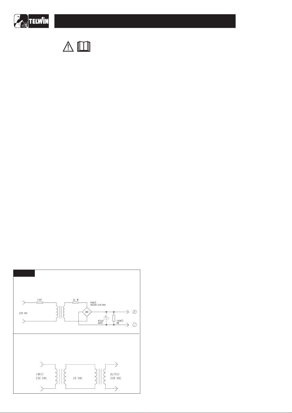
HV POWER SUPPLY MODULE
THE HV POWER SUPPLY is used to ensure operation of the
switching power supply (the circuit on the primary board supplying
auxiliary voltages), even when the machine is operating at low
voltage.
It is easy to build using the electrical diagrams in fig. A for
reference and using the following components or, alternatively, it
can be ordered from Telwin.
T1 = insulation transformer 230-230V 50VA(*)
D1 = rectifier bridge 36MB 80 (cod. 112357)
C1 = electrolytic capacitor 470uF 400V ALL
(cod.112514)
R1 = resistor 10 ohm 5W 5%
R2 = resistor 100K ohm 2W 5%
F1 = delayed action fuse 1.5 A Fuse holder 5X20mm
Female red and black faston
Plastic box.
The following is a list of practical rules which must be strictly
adhered to if repairs are to be carried out correctly.
A) When handling the active electronic components, the IGBT's
and Power DIODES in particular, take elementary antistatic
precautions (use antistatic footwear or wrist straps, antistatic
working surfaces etc.).
B) To ensure the heat flow between the electronic components
and the dissipator, place a thin layer of thermo-conductive
grease (e.g. COMPOUND GREASIL MS12) between the
contact zones.
C) The power resistors (should they require replacement) should
always be soldered at least 3 mm above the board.
D) If silicone is removed from some points on the boards, it should
be re-applied. Use only non-conducting neutral or oximic
reticulating silicones (e.g. DOW CORNING 7093). Otherwise,
silicone that is placed in contact with points at different
potential (rheophores of IGBT's, etc.) should be left to
reticulate before the machine is tested.
E) When the semiconductor devices are soldered the maximum
temperature limits should be respected (normally 300 C for no
more than 10 seconds).
F) It is essential to take the greatest care at each disassembly
and assembly stage for the various machine parts.
G) Take care to keep the small parts and other pieces that are
dismantled from the machine so as to be able to position them
in the reverse order when re-assembling (damaged parts
should never be omitted but should be replaced, referring to
the spare parts list given at the end of this manual).
H) The boards (repaired when necessary) and the wiring should
never be modified without prior authorisation from Telwin.
I) For further information on machine specifications and
operation, refer to the Instruction Manual.
J) When the machine is in operation there are
dangerously high voltages on its internal parts so do not touch
the boards when the machine is live.
Every operation should be carried out in complete
safety with the power supply cable disconnected from the mains
outlet:
After completing the repairs, proceed in the reverse order to re-
assemble the cover and do not forget to insert the toothed washer
on the ground screw.
Using suitably dried compressed air, carefully clean the
components of the power source since dirt is a danger to parts
subject to high voltages and can damage the galvanic separation
between the primary and secondary.
To clean the electronic boards we advise decreasing the air
pressure to prevent damage to the components.
GENERAL REPAIR INSTRUCTIONS
TROUBLESHOOTING AND REMEDIES
N.B.
WARNING!
WARNING!
°
1.0 Disassembling the machine
2.0 Cleaning the inside of the machine
- Undothe8screwsfasteningthe2plasticcovers(4each)tothe
frontandback .
- Undo the 8 screws fastening the top cover to the structure
.
- Slideoutthetopcoverbypullinggentlyoutwards .
- Undothe4 screwsfasteningthe bottomtothestructure
.
(figure1A)
(figure1B) (figure1B)
(figure
1B)
- Separate the top metallic structure from the base and put
it on the work bench(figure 3).
NOTE: Because the base is an integral part of support
structure it
should be removed if it is necessary to gain access to
internal boards.
-14-
TECHNOLOGY TIG 172 AC/DC
10 5
F1 R1
R2
D1
T1
Figure A
ELECTRICAL DIAGRAM FOR POWER SUPPLY (HV OUTPUT):
THE INSULATION TRANSFORMER CAN BE REPLACEDWITH
TWO TRANSFORMERS OF THE SAME POWER,
CONNECTING THE SECONDARIES ACCORDING TO THE
FOLLOWINGDIAGRAM:

It is therefore important to take special care when cleaning the
following parts
Check whether dirt has been deposited on the front and back air
vents or has damaged the correct rotation of the blades, if there is
still damage after cleaning replace the fan.
Make sure there is no mechanical deformation, dent, or damaged
and/or disconnected connector.
Make sure the power supply cable has not been damaged or
disconnected internally and that the fan works with the machine
switched on. Inspect the components and cables for signs of
burning or breaks that may endanger operation of the power
source. Check the following elements:
Use the multimeter to check whether the contacts are stuck
together or open. Probable cause:
- mechanical or electric shock (e.g. bridge rectifier or IGBT in
short circuit, handling under load).
Probable cause:
- see main power supply switch. If the relay contacts are
stuck together or dirty, do not attempt to separate them and
clean them, just replace the relay.
Probable cause:
- mechanical shock;
- machine connected to power supply voltage much higher than
the rated value;
- broken rheophore on one or more capacitor: the remainder will
be overstressed and become damaged by overheating;
- ageing after a considerable number of working hours;
- overheating caused by thermostatic capsule failure.
Probable cause:
- discontinuation in snubber network,
- fault in driver circuit
- poorly functioning thermal contact between IGBT and
dissipator (e.g. loosened attachment screws: check),
- excessive overheating related to faulty operation
Probable cause:
- excessive overheating related to faulty operation.
Probable cause:
- mechanical shock.
Probable cause:
- discontinuation in snubber network;
- poorly functioning thermal contact between IGBT and
dissipator (e.g. loosened attachment screws: check);
- faulty output connection.
Probable cause:
see the main power supply switch; If the relay contacts are
stuck together or dirty, do not attempt to separate or clean them,
just replace the relay.
Check it for colour changes.
Probable cause:
overheating due to loosening of the screws connecting the shunt
to the PCB.
Probable cause:
see the main power supply switch; If the relay contacts are
stuck together or dirty, do not attempt to separate or clean them,
just replace the relay.
Make sure the fuse is correctly inserted into the fuse holder and
that it has not blown (blackened in colour). Use the multimeter to
check whether the fuses have blown. Probable cause:
excessive current absorption from the main supply.
Inspect the windings for colour changes.
Probable causes:
- aging after a substantial number of working hours;
- excessive overheating related to faulty operation.
Inspect the windings for colour changes. Probable causes:
- aging after a substantial number of working hours;
- excessive overheating related to faulty operation.
Check it for colour changes. Probable cause:
- overheating due to loosening of the screws connecting the
shunt to the PCB.
Check the solenoid valve to see if it opens. Probable causes:
- the solenoid valve does not open because of a mechanical
block; do not attempt to open the valve but used compressed air to
carry out thorough cleaning or replace the solenoid valve.
Maintenance status, referring to the instructions given in the
instruction manual. Condition of parts not subject to wear on the
connecting cable between torch and power source (insulation).
It is important to check that all the connections are in good
condition and the connectors are inserted and/or attached
correctly. To do this, take the cables between finger and thumb (as
close as possible to the fastons or connectors) and pull outwards
gently: the cables should not come away from the fastons or
connectors. N.B. If the power cables are not tight enough this
could cause dangerous overheating.
Fan fig. 2A
Main power supply switch fig. 2A
Relays K1, K2 primary board fig. 5
Electrolytic capacitors C2,C4,C6,C7 primary board fig. 5
IGBT's Q1, Q2, Q3, Q4 primary board fig. 5
Primary diodes D1, D4, D6, D8 primary board fig. 5
Mode selector switches SW2 and SW3 panel board (fig. 2A)
Secondary diodes D1...D10 secondary board fig. 2A
Relay K2 secondary board (fig. 6)
Shunt R2 secondary board (fig. 6)
Relay K1 torch button board (fig. 4)
Fuse F1 torch button board (fig. 4)
Power transformer and filter inductance (fig. 2A)
HF transformer (fig. 2A)
Shunt (fig. 2A)
Solenoid valve (fig. 3)
TIG Torch
()
()
()
()
()
.
()
()
Primary board (fig. 5:)
Secondary board (fig. 6):
Power transformer and inductance assembly (fig. 2A)
Parts fastened to the base (fig. 4)
5.0 Electrical measurements with the machine switched off
-
-
-
-
-
-
-
-
-
fig. 5
fig. 5
fig. 6
fig. 6
fig. 5
fig. 5
fig. 6
rheofores of IGBT's Q1, Q2, Q3, Q4;
rheofores of recirculating diodes D4, D8;
rheofores of snubber network diodes D1, D6;
rheofores of opto-couplers ISO1 and ISO2;
rheofores of connectors J4 and J6;
rheofores of secondary power diodes D1…D10;
bump contacts on top of and under the printed circuit of the
SCR Q5 module;
thermostat ST1 on secondary diode dissipator;
rheofores of opto-couplers ISO1, ISO2, ISO3, ISO4;
Do this if it is necessary to remove the primary board, otherwise it
is possible to clean the part superficially from the side of the
secondary board.
If the primary and secondary boards are removed (with the
diaphragm), carefully clean all the parts fastened to the base, or
clean the base partially from the sides of the machine.
A) With the multimeter set on diode testing check the following
components (joint voltages not less than 0.2V):
- rectifier bridges D3, D5 ( );
- IGBT's Q1, Q2, Q3, Q4, (no short circuits between collector-
gate and collector-emitter ( ));
- secondary diodes D1…D10 between anode and cathode
( ). SCR Q5 module (no short circuits between anode
and cathode ).
B) With the multimeter in ohm mode check the following
components:
- resistor R1: 47 ohm (pre-charge ).
- resistors R2, R6: 10 ohm (primary snubber ).
- resistors R1, R2, R3, R4: 10 ohm (secondary snubber ).
- thermostat continuity test on inductance: disconnect fastons
3.0 Visual inspection of the machine
4.0 Checking the power and signal wiring
N.B.
- N.B.
-
- N.B.
-
-15-
TECHNOLOGY TIG 172 AC/DC

J15 and J16 from the control board and make sure the
resistance is approx. 0ohm ( ).
- thermostat continuity test on secondary dissipator:
disconnect fastons J13 and J14 from the control board and
make sure the resistance is approx. 0 ohm ( ).
Switch on the HV power supply (HV OUT) and make sure that
(fig. 5):
- pre-charge relays K1 and K2 close;
- the fan starts to turn for the power transformer;
Make sure the waveform shown on the oscilloscope
resembles .
if there is no signal it may be necessary to replace the
integrated circuit U2 or IGBT Q10 on the primary board ( ).
C) Set up the multimeter in volt mode and make sure the primary
board has the following voltages: ( ):
- between the cathode of diode D32 (+) and the negative of
diode bridge D5 (-): equal to +16.5Vdc 3%;
- between pin 3 (+) and the dissipator (-) of U5: equal to +5Vdc
5%;
- between pin 3 (+) and the dissipator (-) of U4: equal to +12Vdc
5%;
- between pin 3 (+) and pin 1 (-) of U6: equal to -12Vdc 5%;
- between pin 8 (+) and pin 7 (-) of ISO1: equal to +30Vdc 5%;
- between pin 8 (+) and pin 7 (-) of ISO2: equal to +30Vdc 5%;
- between pin 4 (+) and pin 5 (-) of J4: equal to +18Vdc 10%;
- between pin 9 (+) and pin 8 (-) of J4: equal to +18Vdc 10%;
D) Switch off the HV power supply, reposition the control board
and reconnect the wiring.
E) On the front panel set switch SW2 to MMA (as low as it will go)
and switch SW3 to DC-LIFT (in the centre).
F) Switch on the HV power supply (HV out) and make sure that
(fig. 2A):
- the green power supply LED D6 lights up;
- the green LED D7 indicating voltage over the torch lights up;
- the yellow alarm LED D8 is off;
- the display shows a numeric value that varies between 5 and
140 when the encoder is turned.
- with the oscilloscope probe connected as in point 6.1 F) the
wave form resembles ;
- the frequency is equal to 60KHz ±5%; if the frequency reading
on the oscilloscope is not 60KHz ±5%, calibrate the frequency
when the machine is being tested (see point 1.2 A).
if the signal is not present it may be necessary to replace the
integrated circuit U2 or IGBT Q10 on the primary board
G) Switch off the HV power supply.
H) Set up the oscilloscope with the voltage probe x10 connected
between the gate (probe) and the emitter (earth) of IGBT Q4
on the primary board ).
I) Switch on the HV power supply (HV out) and make sure the
waveform displayed on the oscilloscope resembles .
fig. 7
fig. 7
A)
B)
Fig. B
N.B.
fig. 5
fig. 5
fig. C
N.B.
(fig. 7).
(fig. 5
fig. D
6.0 Electrical measurements with the machine in
operation
WARNING!
fig. 3
fig. 4
fig. 5
WARNING!
Before proceeding with faultfinding, we should
remind you that during these tests the power source is powered
and therefore the operator is exposed to the danger of electric
shock.
The tests described below can be used to check the operation of
the power and control parts of the power source.
A) Do not connect the gas mixture source.
B) Disconnect all connectors and fastons from the control board
and remove it from the primary board.
C) From the primary board, disconnect fastons CN3 (XF+) and
CN10 (XF-) for the power transformer ( ), and disconnect
faston J1 from the support board (fig. 5).
D) On the primary board disconnect the jumper on JP1.
E) Connect the HV power supply OUT (code 802403) on the
primary board as follows ( ):
- (+) Positive (clamp) to rheofore of resistor R35 towards
JP1 (after removing jumper JP1);
- (-) Negative (faston) to negative faston of diode bridge D3.
F) Set up the oscilloscope with the voltage probe x100
connected between the rheofore of R40A (collector Q10)
towards JP1 (probe) and the negative of diode bridge D3
(earth) to the primary board ( ).
G) Disconnect fastons J1 and J3 from the HF board (fig. 4).
H) Connect the power supply cable to a single phase variac with
variable output 0-300 Vac.
during testing prevent contact with the metal part of
the torch because of the presence of high voltages that are
hazardous to the operator.
6.1 Preparation for testing
6.1 Scheduled tests
only
-16-
TECHNOLOGY TIG 172 AC/DC
SETTINGS:
· PROBE x10
· 100mV/Div;
· 10 sec/Div.
VERIFY THAT:
· THE FREQUENCY IS
60KHz ±10%;
· AMPLITUDE IS
450V ±10%.
µ
FIGURE C
SETTINGS:
· PROBE x100;
· 100 V/Div;
· 10 sec/Div.
· THE FREQUENCY
IS 35KHz ±15%;
· AMPLITUDE IS
450V ±10%;
µ
VERIFY THAT
FIGURE B
SETTINGS:
· PROBE x10;
· 100mV/Div;
· 5 sec/Div.
TIME TOLLERANCE ± 20%
· POSITIVE AMPLITUDE
IS +18V ±10%;
· NEGATIVE AMPLITUDE
IS -10V ±10%.
µ
VERIFY THAT
FIGURE D

J) Repeat this test on Q1, Q2, Q3 as well. if the signal is not
present there could be a fault in the IGBT driver circuit,
specifically ISO1 and ISO2 ( ), or in the control board (
, in which case we recommend replacing the board).
K) Switch off the HV and replace the 2 fastons connecting the
primary board and the power transformer (CN3 and CN10).
L) Switch on the HV and the variac (initially set to 0V), close the
main power supply switch on the machine and gradually
increase the voltage generated by the variac until it reaches
26Vac.
M) Set up the oscilloscope with the voltage probe x100
connected between the collector (probe) and the emitter
(earth) of IGBT Q4 on the primary board ( ).
N) Make sure the waveform shown on the oscilloscope
resembles
O) Repeat this test on Q2 as well, using the differential probe.
If the signal is not present there may be a fault in the IGBT's
().
P) Return the variac voltage to 0V, switch off the machine and the
HV power supply.
Q) Disconnect the HV power supply, replace jumper JP1 on the
board.
R) Switch the machine on again and gradually increase the
voltage generated by the variac to 150Vac 5% then make sure
an alarm is registered with yellow LED D8 on and alarm “AL.1”
shown on the display.
S) Increase the voltage on the variac to 230Vac and make sure
the alarm ceases (yellow LED D8 goes off).
T) Increase the voltage on the variac yet again to 300Vac 5% and
make sure the machine registers an alarm again. Return the
variac voltage immediately to 230Vac and switch off the
machine.
if an alarm persists (and is not caused by a fault in the control
board) there could be a fault in opto-isolator ISO3 or integrated
circuit U3 on the primary board ( ).
N.B.
fig. 5 fig.
3
fig. 5
fig. E.
N.B.
fig.5
N.B.
fig. 3
7.0 Repairs, replacing the boards
If repairing the board is complicated or impossible, it should be
completely replaced.
The board is identified by a 6-digit code (printed in white on the
component side after the initials TW). This is the reference code
for requesting a replacement: Telwin may supply boards that are
compatible but with different codes.
before inserting a new board check it carefully for
damage that may have occurred in transit. When we supply a
board it has already been tested and so if the fault is still present
after it has been replaced correctly, check the other machine
components. Unless specifically required by the procedure, never
alter the board trimmers.
If the fault is in the control board remove it from the primary board
as follows:
- with the machine disconnected from the main power supply
disconnect all the wiring from the control board;
- cut any bands restricting the board;
- remove the control board from the spacers attached to the
primary board;
for assembly proceed in the reverse order.
If the fault is in the control board we strongly advise replacing it
without further intervention.
If the fault is in the primary board remove it from the machine
structure as follows:
- with the machine disconnected from the main power supply
and after removing the control board, disconnect all the wiring
from the primary board;
- cut any bands restricting the board (e.g. on the power supply
cable and primary connections);
- undo the screws fastening the front and back panels and
remove the panels from the machine structure;
- undo the screws fastening the primary board to the machine
structure;
- remove the primary board by lifting it upwards.
for assembly proceed in the reverse order.
The 4 IGBT's are attached to 2 different dissipators and whenever
a replacement is required, both IGBT's should be replaced.
Before making the replacement make sure the components
piloting the IGBT's are not also damaged:
- with the multimeter set in mode make sure there is no
short circuit on the PCB between the 1 and 3 bump contacts
(between gate and emitter) corresponding to each
component;
- alternatively, resistors R3, R4, R7, R8 could have burst and/or
diodes D11, D12, D15, D16 may be unable to function at the
correct Zener voltage (this should have shown up in the
preliminary tests);
- clean any irregularity or dirt from the dissipators. If the IGBT's
have burst the dissipators may have been irreversibly
damaged: in this case they should be replaced;
- apply thermo-conductive grease following the general
WARNING!
N.B.
N.B.
Please read the procedure for replacing the IGBT's
carefully: (fig. 5).
ohm
7.1 Removing the control board (fig. 3)
7.2 Removing the primary board (fig. 3)
- Unscrew the four (4) nuts that fix the dissipator onto the
card;
- unscrew the four (4) screws that fix the four (4) IGBT onto
the dissipator;
- unscrew the two (2) screws that fix the two diode bridges
onto the dissipator;
- remove the four (4) IGBT and the two (2) diode bridges by
unwelding the reophores, then remove tin from the
printed plates;
- remove dissipator from card.
st rd
-17-
TECHNOLOGY TIG 172 AC/DC
SETTINGS:
· PROBE x10;
· 10V/Div;
· 5 sec/Div.
±
.
· AMPLITUDE IS:
35V ±20%.
µ
TIME TOLLERANCE 20%.
VERIFY THAT
FIGURE E

instructions.
- Prepare the components for replacement. For the IGBT's,
bend the rheofores at 90 (never bend and/or place the parts
under tension near the case).
- Position the components on the dissipator with the fastening
screws, but do not tighten the screws completely
- Join the dissipator/component assembly to the printed board,
inserting all the rheofores in the bump contacts and the
threaded spacers on the 4 attachment holes.
- Attach the dissipators with the nuts and lock them once and for
all in the following order:
- the nuts fastening the dissipators to the printed circuit with a
torque wrench setting of 2 Nm ±20%;
- the screws fastening the rectifiers to the dissipators with a
torque wrench setting of 2 Nm ±20%;
- the screws fastening the IGBT's to the dissipators with a
torque wrench setting of 1 Nm ±20%.
- Solder the terminals taking care not to let the solder run along
them.
- On the component side cut away the protruding part of the
rheofores and check they are not shorted (especially the gate
and emitter).
The 4 IGBT's should belong to the same selection kit
supplied by Telwin.
If the fault is in the secondary board, it should be specified that to
remove it, it is necessary to separate the base from the machine
structure as follows:
- with the machine disconnected from the main power supply
and after removing the control and primary boards, separate
the base from the machine structure by undoing the 4 screws;
- disconnect all wiring connected to the secondary board;
- undo the 4 screws fastening the dissipator to the machine
structure;
- extract the secondary board from the machine structure;
for assembly proceed in the reverse order.
The 10 secondary DIODES are attached to the dissipator and to
reach them it is necessary to remove the boards above and below.
Whenever one diode is replaced, they should all be replaced.
- undo the 3 screws fastening the SCR module to the top board;
- disconnect the 4 fastons connected to the SCR module;
- undo the 2 screws fastening the aluminium connections to the
bottom board;
- remove the top board;
- undo the 4 nuts fastening the bottom board to the dissipator;
- undo the 10 screws attaching the diodes to the dissipater;
- remove the 10 diodes by unsoldering the rheofores and also
remove the solder from the bump contacts on the PCB;
- clean any irregularities or dirt from the dissipators. If the diodes
have burst the dissipator may be irreparably damaged: in such
a case it should be replaced;
- apply thermoconductive paste following the general
instructions; for diodes D6, D7, D8, D9 and D10
remember to insert nomex insulation between the dissipator
and the diode.
- place the dissipator with the new components on the bump
contacts of the PCB and fasten it down with the screws (torque
wrench setting 1 Nm 20%);
- solder the terminals taking care not to let the solder run along
them;
- on the soldering side cut the protruding part of the rheofores
and make sure they have not shorted (between cathode and
anode).
make sure that resistors R1, R2, R3, R4 and capacitors C1,
C2, C3, C4 on the snubber are soldered correctly to the bottom
board.
The SCR module is attached to the dissipator and to reach it, it is
necessary to remove the top board:
- undo the 3 screws fastening the SCR module to the top board;
- disconnect the 4 fastons connected to the SCR module;
- remove the top board;
- remove the SCR module by undoing the 2 screws at the side;
- clean any irregularities or dirt from the dissipators. If the SCR
module has blown the dissipator may be irreparably damaged:
in such a case it should be replaced;
- apply thermoconductive paste following the general
instructions;
- place the new SCR module on the dissipator and fasten it with
the screws (torque wrench setting 5 Nm 20%);
make sure that resistors R1, R6, diodes D22, D5 and
capacitors C1, C5 on the snubber are soldered correctly to the top
board.
Tests should be carried out on the assembled machine before
closing it with the top cover. During tests with the machine in
operation never commute the selectors or activate the ohmic load
contactor.
Before proceeding to test the machine, we should
remind you that during these tests the power source is powered
and therefore the operator is exposed to the danger of electric
shock.
The tests given below are used to verify power source operation
under load.
A) Do not connect the gas mixture source.
B) Connect the machine to the static load generator (code
802110) using cables fitted with the appropriate dinse
connectors (802110)
C) Set up the dual trace oscilloscope with the voltage probe
CH1x100 connected between the collector (probe) and the
emitter of Q4 (earth) on the primary board ( ).
D) Pass the current probe of the Hall effect transducer along the
cable connecting the power transformer at faston CN10 with
the reference arrow pointing into CN10.
E) Lastly, connect the Hall Probe and the current probe to the
oscilloscope.
F) Set up a multimeter in DC volt mode and connect the prods to
the OUT+ and OUT- dinse connections.
G) On the front panel set switch SW2 to MMA (as low as it will go)
and switch SW3 to DC-LIFT (in the centre).
H) Keep fastons J1 and J3 disconnected from the HF board (fig.
3).
the high frequency voltage will permanently damage
any instrument connected to the generator. Before proceeding
make very sure that the fastons listed above are disconnected and
completely isolated from one another.
I) Connect the power supply cable to the 230Vac power supply.
during testing prevent contact with the metal part of
the torch because of the presence of high voltages that are
hazardous to the operator.
Switch on the machine, gradually increase the power supply
voltage from 0V to 230Vac and make sure that:
- the pre-charge relays on the primary board close;
- the fan starts operating correctly;
- the green power supply LED D6 lights up;
- the waveform displayed on the oscilloscope resembles
and the frequency is equal to +60KHz ±5%; if the frequency
°
NOTE.
N.B.
Take special note of the procedure for replacing the
secondary diodes (fig. 6):
Warning!
N.B.
Please take careful note of the procedure for replacing the
SCR module (fig. 6):
N.B.
WARNING!
fig. 5
WARNING!
WARNING!
A) Loadless test:
Fig. F
7.3 Removing the secondary board (fig. 6)
TESTING THE MACHINE
1.1 Preparation for testing
1.2 Scheduled tests
-18-
TECHNOLOGY TIG 172 AC/DC

reading on the oscilloscope is not 60KHz ±5%, adjust the
frequency using trimmer R162 on the control board;
- the output voltage over dinse + and dinse is equal to 110Vdc
15%.
- set up the ohmic load with the switch settings as in the table in
;
- on the front panel use the encoder to position the current at
15A;
- switch on the main switch;
- start up on the ohmic load and make sure that:
- the waveforms displayed on the oscilloscope resemble
those in ;
- the output current is equal to +15Adc 20% and the output
voltage is equal to +15Vdc 5%.
- switch off the ohmic load and switch off the main switch.
- set up the ohmic load with the switch settings as in the table in
;
- on the front panel position with the encoder the current at 140A;
- start up the ohmic load and make sure that:
- the waveforms displayed on the oscillscope resemble those
in ;
- the output current is equal to +80Adc 10% and the output
voltage is equal to +23.2.Vdc 10%.
- switch off the ohmic load and switch off the main switch.
- set up the ohmic load with the switch settings as in the table in
;
- on the front panel position with the encoder the current at 140A;
- start up on the ohmic load and make sure that:
- the waveforms displayed on the oscilloscope resemble
those in ;
- the output current is equal to +140Adc 5% and the output
voltage is equal to +26Vdc 5%; if the output current reading is
not 140A ±3%, adjust the current using trimmer IMAX R105
on the control board ( ).
- switch off the ohmic load and switch off the main switch.
- on the front panel set switch SW2 to TIG/2T (as high as it will
go) and switch SW3 to AC (as low as it will go).
- connect the TIG torch to the machine.
- set up the dual trace oscilloscope, connecting probe CH1 x10
to pin 1 of connector J3, on the control board ( ), and probe
CH2 x 10 to pin 2. The earths are connected together to pin 3
on the same J3 connector;
- set up the ohmic load with the switch settings as in the table in
- on the front panel use the encoder to position the current at
15A;
- start up the ohmic load, press the torch button and make sure
B) Rated load test:
fig. G
Fig. F
C)Intermediate load test:
fig. H
Fig. H
D) Rated load test:
fig. I
Fig. I
fig. 7
E) Testing operation of SCR module
fig. 7
Fig. J;
±
±
±
±
-19-
TECHNOLOGY TIG 172 AC/DC
FIGURE F
FIGURA E
FIGURE G
6
3
2
145
110000Number switch
Number switch
Number switch
Position switch
Position switch
Position switch
FIGURA E
6
3
2
145
222210
FIGURE H
FIGURA E
6
3
2
145
333222
FIGURE I
SETTINGS
· THE FREQUENCY IS
60KHz ±5%;
· AMPLITUDE CH1 IS
340V ±10%;
:
· PROBE CH1 x100;
· 100 V/Div;
· PROBE CH4 =1A;
· 10mV/Div;
· 5 sec/Div.µ
VERIFY THAT
SETTINGS
· THE FREQUENCY IS
60KHz ±5%;
· AMPLITUDE CH1 IS
340V ±10%;
· AMPLITUDE CH4 IS 7A
±20%;
:
· PROBE CH1 x100;
· 100 V/Div;
· PROBE CH4 =5A;
· 10mV/Div;
· 5 sec/Div.µ
VERIFY THAT
SETTINGS
· THE FREQUENCY IS
60KHz ±5%;
· AMPLITUDE CH1 IS
340V ±10%;
· AMPLITUDE CH4 IS
26A ±20%;
:
· PROBE CH1 x100;
· 100 V/Div;
· PROBE CH4 =10A;
· 10mV/Div;
· 5 sec/Div.µ
VERIFY THAT
SETTINGS
· THE FREQUENCY IS
60KHz ±5%;
· AMPLITUDE CH1 IS
340V ±10%;
· AMPLITUDE CH4 IS
46A ±10%;
:
· PROBE CH1 x100;
· 100 V/Div;
· PROBE CH4 =20A;
· 10mV/Div;
· 5 sec/Div.µ
VERIFY THAT

the waveforms displayed on the oscilloscope resemble those
in .
- switch off the ohmic load and switch off the main switch.
If one of the two signals is absent the control board should be
replaced ( Otherwise, if the machine does not supply AC
current the SCR module should be replaced, or if the worst comes
to the worst replace the secondary board.
Set switch SW2 to TIG/2T (toward to the top) and switch SW2 to
LIFT (in the centre). Connect the TIG torch and press the button to
verify that relay K1 closes ; if not check whether:
After checking operation for point 1.3 A), press the button and
check whether:
- the solenoid valve closes (fig. 2A); if not check whether:
- the voltage over the female fastons ( ) is equal to 230Vac
±10%. If voltage is present this means the solenoid valve is
faulty, otherwise check the operation of relay K2 on the
secondary board;.
-
- the voltage over pin 1 (+) and pin 25 of J9 (control board) is
equal to +15Vdc ±20%, otherwise replace the control board.
Set switch SW2 to TIG/2T (as high as it will go) and switch SW3 to
AC (as low as it will go). Now reconnect only fastons J1 and J3 to
the HF generator board ( ) and faston J1 on the support
board.
The high frequency voltage will permanently damage
any instrument connected to the generator.
With the TIG torch still connected and pressing the button check
whether:
- the HF generator board starts to hum for about 2 seconds
(high frequency in torch); otherwise make sure the voltage
over female fastons J1 and J3 ( ), disconnected from the
HF board, is equal to 230Vac ±10%; if voltage is present the
HF board is faulty; if not check the operation of transformer T1
and SCR Q1;
On the front panel set switch SW2 to MMA (as low as it will go),
switch SW3 to DC-LIFT (in the centre) and the welding current to
maximum. Under the load conditions shown in , switch on the
machine and leave it in operation until the thermostatic capsules
trigger (machine in alarm). After making sure the internal wiring is
positioned correctly re-assemble the machine once and for all.
with the machine set up according to the instructions in the
handbook make a test weld with an electrode diam. 2.5 and the
current setting at 80A. Monitor the dynamic behaviour of the
power source, also checking for the presence of the Arc Force, by
first operating key SW1 and then the encoder.
with the machine set up according to the instructions in
the handbook make a test weld with a grey electrode diam. 2.4
and an argon gas bottle (gas flow at 4.5 litres/minute). Make a
weld on iron or steel with a current setting of 80A, monitor the start
and arc stability and make sure the piece melts properly. Also
check all the main properties of the machine that can be set from
the digital panel (see TAB.1).
with the machine set up according to the instructions in
the handbook make a test weld with a green electrode, diam.
1.6mm, and the argon gas bottle (gas flow at 10 litres/minute).
Make a weld on aluminium with a current setting of 40A and
Duty Cycle 80%, monitor the start and arc stability and make
sure the piece melts properly. Also check all the main properties
of the machine that can be set from the digital panel (see
TAB.1).
Fig. J
N.B.
fig. 3).
A) Checking torch button operation
(fig. 4)
B) Checking solenoid valve operation
fig.4
on the secondary board relay K2 closes (fig. 6); if not check
whether:
C)Checking HF generator operation
fig. 4
WARNING!
fig.4
D) Running time test and closing the machine
fig. I
E) Welding test
MMA:
TIG/DC:
TIG/AC:
1.3 Operational tests
- Operation of the torch button;
- Operation of diode bridge D2 on the torch button board;
- Operation of transformer T1 on the torch button board;
- 20-
TECHNOLOGY TIG 172 AC/DC
FIGURA E
6
3
2
145
110000
FIGURE J
SETTINGS
· THE FREQUENCY ON
CH1 AND CH2 IS
45KHz ±10%;
· AMPLITUDE ON CH1
AND CH2 IS 12V ±10%;
:
· PROBE CH1 x10;
· 5 V/Div;
· PROBE CH2 =10;
· 5V/Div;
· 10 sec/Div.µ
VERIFY THAT
Number switch
Position switch
Table of contents
Other Telwin Inverter manuals


 Mk II instruction manual")


