manuals.online logo
Brands
  1. Home
  2. •
  3. Brands
  4. •
  5. Siemens
  6. •
  7. Industrial Equipment
  8. •
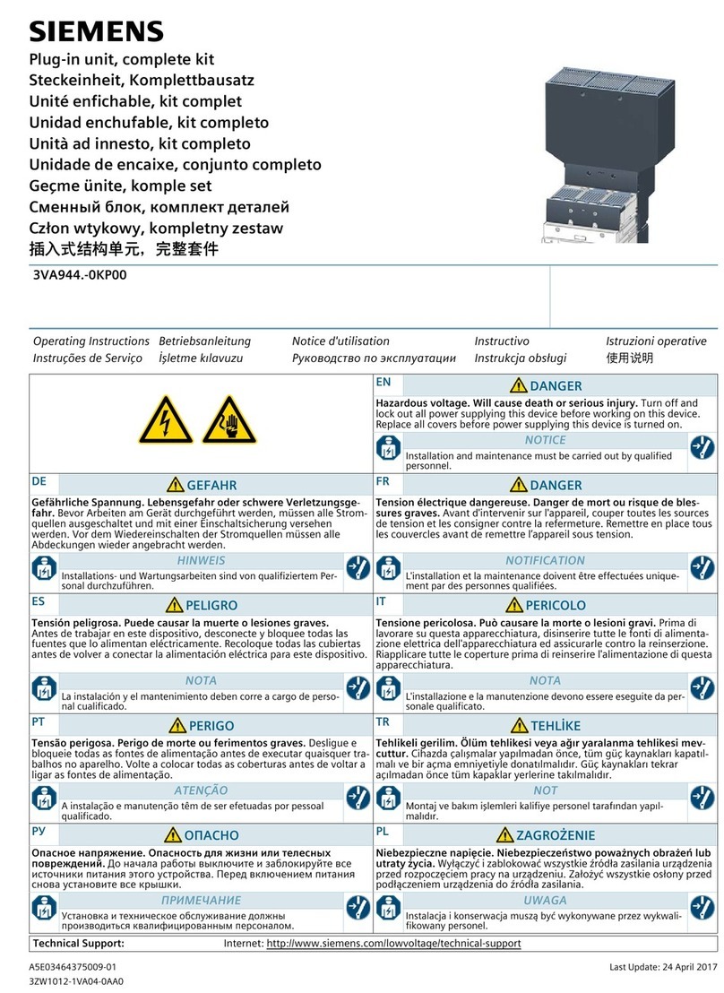
  9. Siemens FDHANDLE User manual

Siemens FDHANDLE User manual

FDHANDLE
s
Handle and Shield
Replacement kit.
Installation Instructions / Instructivo de Instalación
Use only with Siemens certified Components.
Utilizar únicamente con componentes certificados por Siemens.
A utiliser uniquement avec les composants certifiés Siemens.
Item: FDHANDLE
Turn off and lock out all power supplyingthis device before
working on this device.
Replace all covers and close the enclosure door before
power supplying this device is turned on.
Couper l'alimentation de l'appareil et barrer avant de
travailler.
Remplacez touts les couverts avant que
l'approvisionnement de pouvoirsoit alimenté.
Tensión peligrosa.
Puede causar la muerte o lesiones graves. Tension dangereuse.
Danger de mort ou risque de blessures graves.
Hazardous Voltage
Will cause death or serious injury Desenergice totalmente antes de instalar o darle servicio.
Reemplace todas las barreras y cubiertas antes de
energizar el interruptor.
For use with Types:
Circuit Breakers: FXD6-A, FD6-A, HFXD6, HFD6,
HHFD6, HHFXD6, FFC, FFF and CFD6.
Motor Circuit Interrupters:FXD6ETI, CFD6ETI
Molded Case Switches : FXD6,FXD6-A, CFD6
NOTE - These instructions do not purport to cover
all details or variations in equipment, or to provide
for every possible contingency to be met in
connection with installation, operation or maintenance.
Should further information be desired or
should particular problems arise, which are not
covered sufficiently for the purchaser’s purposes,
the matter should be referred to the local Siemens
sales office. The contents of this instruction
manual shall not become part of or modify any
prior or existing agreement, commitment or
relationship. The sales contract contains the entire
obligation of Siemens. The warranty contained in
the contract between the parties is the sole
warranty of Siemens. Any statements contained
herein do not create new warranties or modify the
existing warranty.
Trademarks - Unless otherwise noted, all names
identified by ® are registered trademarks of
Siemens AG or Siemens Industry, Inc.
The remaining trademarks in this publication may
be trademarks whose use by third parties for their
own purposes could violate the rights of the owner.
1 / 5 I.L. No. 810519A00
For Use With: Frame FD, FM
Para Usar Con Caja Base: FD, FM
Cal. ISO 6789
810519A00
Released Production, 0P v5, Apr 26, 2011
Turn off and lock out all power supplyingthis device before
working on this device.
Replace all covers and close the enclosure door before
power supplying this device is turned on.
Couper l'alimentation de l'appareil et barrer avant de
travailler.
Remplacez touts les couverts avant que
l'approvisionnement de pouvoirsoit alimenté.
Tensión peligrosa.
Puede causar la muerte o lesiones graves. Tension dangereuse.
Danger de mort ou risque de blessures graves.
Hazardous Voltage
Will cause death or serious injury Desenergice totalmente antes de instalar o darle servicio.
Reemplace todas las barreras y cubiertas antes de
energizar el interruptor.
2 / 5 I.L. No. 810519A00
2. Remove and retain Cover Screws.
Circuit Breaker or
Motor Circuit
Interrupter (ETI)
d
Tripped
Press red “Push
to Trip” button
c
b
OFF / O
Molded Case Switch
1. Prepare device for handle replacement.
Turn OFF and lock out all power supplying this device before working on this device.
Turn OFF Molded Case Switch.
Press red “Push to Trip” button to trip Circuit Breaker or Motor Circuit Interrupter (ETI).
Verify Circuit Breaker or Motor Circuit Interrupter (ETI) is tripped or Molded Case Switch is OFF.
a
b
c
d
Cover Screws:
(3) 6-32 X 3/8” Pan Head
Cover Screws :
(2) 6-32 X 1-1/4” Round Head
5X
Released Production, 0P v5, Apr 26, 2011
3 / 5 I.L. No. 810519A00
4. Remove and discard handle and shield.
3. Remove and retain cover.
5. Remove old lubricant on inside of trip unit cover.
WARNING
Pieces of broken handle or shield
could interfere with device operation.
All broken pieces must be
retrieved from this device.
Do not continue use of device if
all pieces are not retrieved.
Handle Shield
Use clean cloth to thoroughly
clean the area indicated.
WARNING
Adding lubrication may result in damage
to the handle shield.
Do not use lubrication on handle shield.
Notice: Molded Case Switch
mechanism will move to the
tripped position as cover is
removed.
Released Production, 0P v5, Apr 26, 2011
aAssembly with tabs
to the same side.
Turn off and lock out all power supplyingthis device before
working on this device.
Replace all covers and close the enclosure door before
power supplying this device is turned on.
Couper l'alimentation de l'appareil et barrer avant de
travailler.
Remplacez touts les couverts avant que
l'approvisionnement de pouvoirsoit alimenté.
Tensión peligrosa.
Puede causar la muerte o lesiones graves. Tension dangereuse.
Danger de mort ou risque de blessures graves.
Hazardous Voltage
Will cause death or serious injury Desenergice totalmente antes de instalar o darle servicio.
Reemplace todas las barreras y cubiertas antes de
energizar el interruptor.
4 / 5 I.L. No. 810519A00
6. Prepare new handle for assembly.
If the handle shield is separate from the handle, snap them together as shown below.
Apply appropriate rating label from kit to handle
a
b
7. Install Handle assembly.
Orient both tabs
to trip unit side
Align recessed areas
under handle with
mechanism pin and
rectangular spring guides.
Example 100
Amp shown
b
Released Production, 0P v5, Apr 26, 2011
OFF / O
ON / I
Subject to change without prior notice © Siemens Industry Inc. 2010
Siemens Industry, Inc. , Norcross,GA 30092 U.S.A.
Technical Support: Telephone: 1-800-241-4453 Internet: www.usa.siemens.com/powerdistribution
5 / 5 I.L. No. 810519A00
8. Reassemble cover and cover screws.
10. Test Operation
•Cycle device from OFF to ON to OFF to verify
operation. Call Technical Support if device does
not operate correctly.
•Turn OFF device.
•Replace all covers and close the enclosure door
before power supplying this device is turned on.
Cover
Screws
Cover
Screws
Cover Screws :
(2) 6-32 X 1-1/4” Round Head
Cover Screws:
(3) 6-32 X 3/8” Pan Head
9. Move handle from TRIP to OFF position
Tripped OFF / O
3X 12 lb. in.
[1.3 Nm]
2X 12 lb. in.
[1.3 Nm]
Released Production, 0P v5, Apr 26, 2011

Other Siemens Industrial Equipment manuals

Siemens Siprotec 5 7SS85 Instruction manual

Siemens

Siemens Siprotec 5 7SS85 Instruction manual

Siemens SINAMICS S120 Technical Document

Siemens

Siemens SINAMICS S120 Technical Document

Siemens Sivacon S8 User manual

Siemens

Siemens Sivacon S8 User manual

Siemens MICROMASTER 440 User manual

Siemens

Siemens MICROMASTER 440 User manual

Siemens SIMATIC NET SCALANCE M-800 User manual

Siemens

Siemens SIMATIC NET SCALANCE M-800 User manual

Siemens SIRIUS 3RT263-1 Series User manual

Siemens

Siemens SIRIUS 3RT263-1 Series User manual

Siemens SIMATIC ET 200eco PN User guide

Siemens

Siemens SIMATIC ET 200eco PN User guide

Siemens 3VL91125GA30 User manual

Siemens

Siemens 3VL91125GA30 User manual

Siemens SIMATIC ET 200eco PN Technical Document

Siemens

Siemens SIMATIC ET 200eco PN Technical Document

Siemens SIMOGEAR BA 2039 User manual

Siemens

Siemens SIMOGEAR BA 2039 User manual

Siemens SIMOTION D410 User manual

Siemens

Siemens SIMOTION D410 User manual

Siemens BD2 User manual

Siemens

Siemens BD2 User manual

Siemens ASK41NF10SP User manual

Siemens

Siemens ASK41NF10SP User manual

Siemens Flender H2NV Series User manual

Siemens

Siemens Flender H2NV Series User manual

Siemens 8GK6430 - 4KK24 User manual

Siemens

Siemens 8GK6430 - 4KK24 User manual

Siemens SIVACON S User manual

Siemens

Siemens SIVACON S User manual

Siemens Simatic S7-300 User manual

Siemens

Siemens Simatic S7-300 User manual

Siemens 3VA932 0RL30 Series User manual

Siemens

Siemens 3VA932 0RL30 Series User manual

Siemens 3VA9578-0VM10 User manual

Siemens

Siemens 3VA9578-0VM10 User manual

Siemens Desigo PXC4.E16 User manual

Siemens

Siemens Desigo PXC4.E16 User manual

Siemens SIMOTICS T-1FW6 User manual

Siemens

Siemens SIMOTICS T-1FW6 User manual

Siemens SIREMOBIL Compact L User instructions

Siemens

Siemens SIREMOBIL Compact L User instructions

Siemens SIMATIC Power Line Booster User manual

Siemens

Siemens SIMATIC Power Line Booster User manual

Siemens SIRIUS 3RV1913 User manual

Siemens

Siemens SIRIUS 3RV1913 User manual

Popular Industrial Equipment manuals by other brands

ABB +Q957 user manual

ABB

ABB +Q957 user manual

G.B.C BASIC EDGE 50 instruction manual

G.B.C

G.B.C BASIC EDGE 50 instruction manual

Tronair Batpak 11-6602-1000 Operation & service manual

Tronair

Tronair Batpak 11-6602-1000 Operation & service manual

Pilz PNOZ mi2p Operation manual

Pilz

Pilz PNOZ mi2p Operation manual

Clemco Zero BNP 6012 manual

Clemco

Clemco Zero BNP 6012 manual

Erskine Attachments V-Plow Operator's manual

Erskine Attachments

Erskine Attachments V-Plow Operator's manual

ABB HT610965 Operation manual

ABB

ABB HT610965 Operation manual

Morra MH 540 user manual

Morra

Morra MH 540 user manual

Eaton S090ST manual

Eaton

Eaton S090ST manual

GRIGGIO G 240 P4 instructions

GRIGGIO

GRIGGIO G 240 P4 instructions

Nexen AIR CHAMP HT45 user manual

Nexen

Nexen AIR CHAMP HT45 user manual

WTE V5 installation manual

WTE

WTE V5 installation manual

ABB HT845232 Operation manual

ABB

ABB HT845232 Operation manual

SMC Networks CJP Series Operation manual

SMC Networks

SMC Networks CJP Series Operation manual

JohnDow Industries JDI-AFT58 Operator's manual

JohnDow Industries

JohnDow Industries JDI-AFT58 Operator's manual

IMB MB9016A instruction manual

IMB

IMB MB9016A instruction manual

Clarke CUMB1 Assembly & operating instructions

Clarke

Clarke CUMB1 Assembly & operating instructions

amiad Arkal Spin Klin 2 user guide

amiad

amiad Arkal Spin Klin 2 user guide

manuals.online logo
manuals.online logoBrands
  • About & Mission
  • Contact us
  • Privacy Policy
  • Terms and Conditions

Copyright 2025 Manuals.Online. All Rights Reserved.