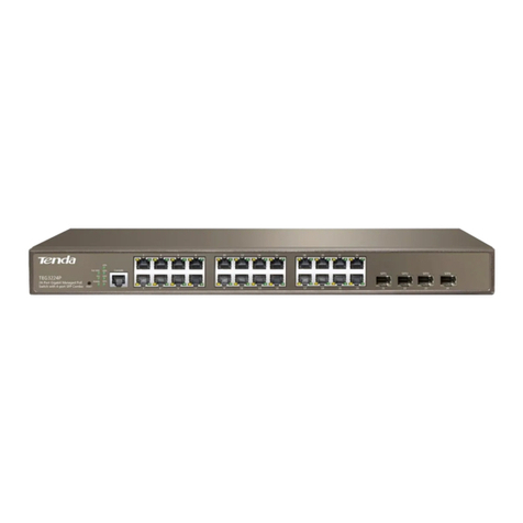
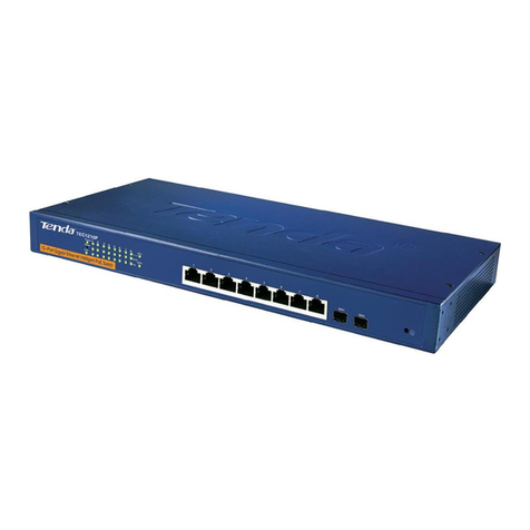
Tenda TEG3224T User manual

24-Port Managed Gigabit Switch

24-Port Managed Gigabit Switch
Copyright Statement
is the registered trademark of Shenzhen Tenda
Technology Co., Ltd. All the products and product names mentioned
herein are the trademarks or registered trademarks of their respective
holders. Copyright of the whole product as integration, including its
accessories and software, belongs to Shenzhen Tenda Technology Co.,
Ltd. Without the permission of Shenzhen Tenda Technology Co., Ltd,
any individual or party is not allowed to copy, plagiarize, imitate or
translate it into other languages.
All the photos and product specifications mentioned in this guide are for
references only. As the upgrade of software and hardware, there will be
changes. And if there are changes, Tenda is not responsible for
informing in advance. If you want to know more about our product
information, please visit our website at www.tenda.cn.
Hint:
On the included CD-ROM, there are Chinese and English Web and
CLI User Guide. For better operation, the Web User Guide is
printed.

24-Port Managed Gigabit Switch
CONTENTS
Chapter 1 Product Introduction ..............................................................1
1.1 Physical Port .............................................................................1
1.2 Layer 2 Features .......................................................................2
1.3 Management .............................................................................3
1.4 Package Contents.....................................................................3
1.5 .............................................................................4Installation
1.5.1 ..........................................4Desktop/Horizontal Installation
1.5.2 ..................5Rack-mountable Installation in 19-inch Cabnit
1.5.3 .........................................................6Power on the Switch
1.6 External Component Description...............................................6
1.6.1 .......................................................................6Front Panel
1.6.2 ........................................................................7Rear Panel
1.6.3 Side Panels........................................................................7
1.6.4 LED Indicator Specification ................................................7
Chapter 2 Connecting the Switch ..........................................................9
2.1 ...............................................................9Switch to End Node
2.2 ....................................................9Switch to Switch or Router
2.3 ......................................................10How to Login the Switch
Chapter 3 Switch Configuration ...........................................................14
i

24-Port Managed Gigabit Switch
3.1 Web Login ...............................................................................14
3.2 Web Configuration Interface....................................................15
3.3 System Configuration..............................................................16
3.3.1 System Information Configuration....................................16
3.3.2 IP and Time Configuration ...............................................17
3.3.3 Account............................................................................19
3.3.4 Power Save Configuration ...............................................20
3.4 Port Configuration ...................................................................21
3.5 Aggregation Mode Configuration ............................................23
3.5.1 Introduction to Link Aggregation ......................................23
3.5.2 Link Aggregation Characteristics .....................................24
3.5.3 Link Aggregation Requirement for Port Settings ..............25
3.5.4 Aggregation Configuration ...............................................27
3.6 Spanning Tree Configuration...................................................30
3.6.1 STP Introduction ..............................................................30
3.6.2 802.1d STP ......................................................................30
3.6.3 Spanning Tree System Configuration...............................35
3.6.4 RSTP Port Configuration..................................................36
3.7 802.1x Configuration ...............................................................39
3.7.1 802.1x Introduction ..........................................................39
3.7.2 802.1x Configuration........................................................40
3.8 IGMP Snooping.......................................................................44
3.8.1 IGMP Snooping Introduction ............................................44
3.8.2 IGMP Snooping Working Mechanism ..............................45
ii

24-Port Managed Gigabit Switch
3.8.3 IGMP Snooping Configuration .........................................47
3.9 LLDP .......................................................................................48
3.9.1 LLDP Introduction ............................................................48
3.9.2 LLDP Configuration..........................................................48
3.10 MAC Address Table Configuration ........................................51
3.10.1 ....................................................51Aging Configuration
3.10.2 ...................................................51MAC Table Learning
3.10.3 ..................................52Static MAC Table Configuration
3.11 VLAN .....................................................................................54
3.11.1 What is a VLAN............................................................54
3.11.2 ........................................................54VLAN Advantages
3.11.3 .............................................56Several Types of VLANs
3.11.4 VLAN Memberships Configuration ...............................56
3.11.5 VLAN Port Configuration ..............................................58
3.12 Quality of Sevice (QoS).........................................................60
3.12.1 QoS Introduction ............................................................60
3.12.2 Well-known Priority ........................................................60
3.12.3 Scheduling Mechanism ..................................................63
3.12.4 QoS Configuration .........................................................64
3.13 Access Control List (ACL) .....................................................73
3.13.1 ACL Introduction ............................................................73
3.13.2 ACL Configuration..........................................................73
3.14 Port Mirroring ......................................................................104
3.14.1 Mirroring Introduction ...................................................104
iii
24-Port Managed Gigabit Switch
3.14.2 Mirroring Configuration ................................................105
3.15 Simple Network Management Protocol (SNMP) .................107
3.15.1 SNMP Introduction .......................................................107
3.15.2 SNMP Configuration ....................................................107
Chapter 4 Switch’s Monitor ................................................................ 110
4.1 System .................................................................................. 110
4.1.1 Information ..................................................................... 110
4.1.2 System Log .................................................................... 111
4.1.3 Detailed Log................................................................... 112
4.2 Ports...................................................................................... 113
4.2.1 Traffic Overview ............................................................. 113
4.2.2 QoS Statictics................................................................. 114
4.2.3 Port Statistics ................................................................. 115
4.3 LACP..................................................................................... 118
4.3.1 LACP System Status...................................................... 118
4.3.2 LACP Port Stauts ........................................................... 119
4.3.3 LACP Statistics ..............................................................120
4.4 Spanning Tree.......................................................................121
4.4.1 Bridge Status..................................................................121
4.4.2 RSTP Port Status...........................................................122
4.4.3 RSTP Statistics ..............................................................123
4.5 802.1x ...................................................................................125
4.5.1 Port Status .....................................................................125
iv

24-Port Managed Gigabit Switch
v
4.5.2 802.1x Port Statistics .....................................................126
4.6 IGMP Snooping.....................................................................129
4.7 LLDP .....................................................................................131
4.7.1 LLDP Neighbours...........................................................131
4.7.2 LLDP Port Statistics .......................................................132
4.8 MAC Address Table ..............................................................134
Chapter 5 Switch’s Diagnostics .........................................................136
5.1 ICMP Ping .............................................................................136
5.2 VeriPHY ................................................................................137
Chapter 6 Switch’s Maintenance .......................................................138
6.1 System Reboot......................................................................138
6.2 Restore to Factory Default Setting ........................................ 138
6.3 Firmware Update...................................................................139
6.4 Settings Upload.....................................................................140
6.5 Settings Dowload ..................................................................140
6.6 Syslog Download ..................................................................141
Chapter 7 Appendix ...........................................................................142
7.1 Product Specification.............................................................142
7.2 Glossary................................................................................144
7.3 Online Technical Support ......................................................162
7.4 Common Commands ............................................................163
7.5 TCP/IP Address Setting (Windows XP as Example) .............164

24-Port Managed Gigabit Switch
Chapter 1 Product Introduction
TEG3224T 24-Port Managed Gigabit Switch was designed for
departmental and enterprise connections. It provides 24
10/100/1000Mbps RJ-45 ports, plus 2 Gigabit mini-GBIC (SFP) combo
ports. Supporting IEEE 802.1x authentication standard and IGMP
Snooping, it also supports 802.1Q VLAN, Trunk, Port Mirroring, 802.1d
STP (Spanning Tree Protocol), and provides Web, Telnet, CLI
(Command Line Interface), SNMPv1, SNMPv2c network management
ways. Powerful and versatile, it is a favorable solution for enterprises
and Internet cafes backbone and server connection in enterprises and
Internet cafes. Its main features are made up mainly of the following
parts:
1.1 Physical Port
Provides 24 high-performance 1000BASE-T ports to be
connected with a backbone, servers, and end stations at
10/100/1000M bps.
2 Gigabit SFP combo ports to connect another switch, server
or network backbone with fiber optic media.
1 RS-232 console port for Switch basic management and setup
via a connection to a console terminal or PC using a terminal
emulation program.
1

24-Port Managed Gigabit Switch
1.2 Layer 2 Features
Provides Store-and-forward architecture
Supports up to 48Gbps backplane bandwidth
Max. forwarding rate: 1488095pps per port (64 bit for each packet.)
Supports 8K MAC address entries
Supports jumbo frame forwarding
Supports DSCP and 802.1p priority with 4 priority queues per port
Provides frame buffer cache
Supports 802.1QVLAN (1-4094) with up to 64 VLANs
Supports IGMP V1 and V2
Supports 802.1x port-based authentication
Supports IEEE 802.3x for full-duplex and Backpressure for
half-duplex
Supports ACL (Access Control List)
Spanning Tree Algorithm Protocol for creation of alternative
backup paths and prevention of network loops, including
802.1w Rapid Spanning Tree (RSTP) and 802.1d Spanning Tree
Supports link aggregation, including static aggregation mode
and LACP, and supports up to 12 Trunk groups and 16 Trunk
members per group
Supports LLDP (Link Layer Discovery Protocol)
Supports port mirroring
Supports Multicast, Broadcast storm and unknown unicast
control
Supports TFTP and HTTP firmware upgrade methods
Supports CLI, Web, Telnet, SNMP V1 and SNMP V2c
management features
Supports syslog
2

24-Port Managed Gigabit Switch
1.3 Management
RS-232 console port for out-of-band network management via
a console terminal
SNMP V1 and V2c network management
Built-in SNMP management:
RFC1213:system, interface, ip, icmp, tcp, udp and snmp
EtherLike-MIB:dot3 StatsTable
Bridge-MIB:dot1Base
IF-MIB:ifXTable
Supports Web-based management
Support remote Telnet management with up to 5 users in the
same time
Supports CLI (Command Line Interface)
1.4 Package Contents
One TEG3224T Managed Gigabit Switch
Four rubber feet, two mounting ears and eights screws
One AC power cord
One Serial cable
One Ethernet network cable
One User Guide
One CD-ROM
3

24-Port Managed Gigabit Switch
1.5 Installation
Please follow the following instructions in avoid of incorrect
installation causing device damage and security threat.
Put the Switch on stable place or desktop in case of falling
damage.
Make sure the Switch works in the proper AC input range and
matches the voltage labeled on the Switch.
To keep the Switch free from lightning, do not open the Switch’s
shell even in power failure.
Make sure that there is proper heat dissipation from and
adequate ventilation around the Switch.
Make sure the cabinet to enough back up the weight of the
Switch and its accessories.
1.5.1 Desktop/Horizontal Installation
Sometimes users are not equipped with the 19-inch standard cabnit.
So when installing the Switch on a desktop, please attach these
cushioning rubber feet provided on the bottom at each corner of the
Switch in case of the external vibration. Allow adequate space for
ventilation between the device and the objects around it. Please
refer to the following figure:
4

24-Port Managed Gigabit Switch
1.5.2 Rack-mountable Installation in 19-inch Cabnit
The TEG3224T can be mounted in an EIA standard-sized,
19-inch rack, which can be placed in a wiring closet with other
equipment. To install, attach the mounting brackets on the
Switch’s side panels (one on each side) and secure them with
the screws provided.
Then, use the screws provided with the equipment rack to
mount the Switch on the rack and tighten it.
Note:
For safety, please read the installation instruction carefully before
installing the device.
5

24-Port Managed Gigabit Switch
1.5.3 Power on the Switch
The Switch is powered on by the AC 100-240V 50/60Hz internal
high-performance power supply. Please follow the next tips to
connect:
1.5.3.1 AC Electrical Outlet
It is recommended to use single-phase three-wire receptacle
with neutral outlet or multifunctional computer professional
receptacle. Please make sure to connect the metal groud
connector to the grounding source on the outlet.
1.5.3.2 AC Power Cord Connection
Step 1: Connect the AC power connector in the back panel of
the Switch to external receptacle with the included
power cord.
Step 2: To check the power indicator is ON or not. When it is
ON, it indicates the power connection is OK.
1.6 External Component Description
1.6.1 Front Panel
The front panel of TEG3224T consists of 24 10/100/1000Mbps
RJ-45 ports, 2 Gigabit SFP combo ports, 1 RS-232 Console port
and a series of LED indicators shown as below.
Front panel view
6

24-Port Managed Gigabit Switch
1.6.2 Rear Panel
The rear panel of TEG3224T contains AC power connector and one
marker shown as below.
Rear panel view
1.6.3 Side Panels
The right side panel of the Switch contains two system fans. The left
side panel has heat vents as shown below.
Side panels view
1.6.4 LED Indicator Specification
LED indicator view
7

24-Port Managed Gigabit Switch
The LED indicators of the TEG3224T contain one Power, one SYS,
26 Link/Act (including 2 SFP indicators) and 24 10/100/1000Mbps
indicators. You can see their operating situation through these LED
indicators.
The following chart shows the LED indicators of the Switch along
with explanation of each indicator.
LED Indicator Status Description
ON Indicates the Switch is powered on well.
POWER
OFF
Indicates the Switch is not powered on well.
Please make sure the power cord’s correct
connection between connector and recepta-
cle.
ON Indicates the Switch is working well.
OFF
Indicates the Switch does not work or works
abnormally.
SYS
Blinking
Indicates the system’s upgrading is in
progress.
ON Indicates the ports are connected well.
OFF
Indicates the port connection is not
established. Please check if the connections
are OK.
Link/Act
Blinking
Indicates the port is transmitting and/or
receiving data packets.
Green Indicates the transmission speed is 1000Mbps.
Orange Indicates the transmission speed is 100Mbps.
Speed
OFF
Indicates the transmission speed is 10Mbps or
there is no connection.
8

24-Port Managed Gigabit Switch
Chapter 2 Connecting the Switch
2.1 Switch to End Node
Use standard Cat.5/5e Ethernet cable (UTP/STP) to connect the
Switch to end nodes as described below. Switch ports will
automatically adjust to the characteristics (MDI/MDI-X, speed,
duplex) of the device to which is connected.
Switch connecting to an end node
Please refer to the LED Indicator Specification. The Link/Act
LEDs for each port lights green when the link is available.
2.2 Switch to Switch or Router
Use the standard Cat.5/5e Ethernet cable (UTP/STP) to uplink the
Switch’s any port to other switch or router as shown below.
Connect to another switch or router
9

24-Port Managed Gigabit Switch
Please refer to the LED Indicator Specification. The Link/Act
LEDs for each port lights green when the link is available.
2.3 How to Login the Switch
TEG3224T provides the following login ways as below.
1. By Web-based management interface using such web browser
as Netscape Navigator, Internet Explorer or firefox. More
details refer to the Web Login part of the Switch
Configuration section.
2. By connecting to the Console Port (RS-232 DCE) serial port on
the front panel of the Switch, which needs a computer or
terminal for monitoring and configuring the Switch.
Step1: Connect the Switch’s console port to the serial connector of
a computer with the RS-232 cable and tighen the captive
retaining screws on both ends.
Console port connection
Step2: On the PC run the terminal emulation software (take the
super terminal on Windows XP as example) and follow the
below to configure the parameters.
Select the appropriate serial port.
Set the data rate to 115200bit/s.
Set the data format to 8 data bits, 1 stop bit, and no parity.
Set flow control to none.
10

24-Port Managed Gigabit Switch
Figure 3-2 Create a new connection
Figure 3-3 Connected port connection
Figure 3-4 Com1 port configurations
11

24-Port Managed Gigabit Switch
Step3: Power on the Switch and the self-test result will be shown
on the terminal device. After the self-test, enter the User
Name and Password (admin/admin by default for
administrator; user/user for common users) and press Enter.
The command prompt will be shown as below.
Figure 3-5 Switch Configuration Interface
3. By Telnet
Step1: Select Start on your computer and click Run.
Step2: In the appearing window enter the command: telnet
192.168.0.1 and press Enter. The following window will
be displayed as below.
12

24-Port Managed Gigabit Switch
13
Hint:
How to configure the device via Telnet or Console port please refers
to the CLI User Guide on included CO-ROM.
Table of contents
Other Tenda Switch manuals

Tenda
Tenda TEG1216T User manual

Tenda
Tenda TEG1024D User manual

Tenda
Tenda TEH1226G User manual

Tenda
Tenda TEG3224P User manual

Tenda
Tenda TEG1210P User manual

Tenda
Tenda TEG1224T User manual

Tenda
Tenda S108 User manual

Tenda
Tenda TEG1024G User manual

Tenda
Tenda TEG1008S User manual

Tenda
Tenda TEH1208 User manual
Popular Switch manuals by other brands

Linksys
Linksys SR216 user guide

steute
steute ZS 80 Extreme Mounting and wiring instructions

HP
HP 2610 Advanced traffic management guide

Larson Electronics
Larson Electronics EXP-EL-CSS-250A-R1-NO instruction manual

Pepperl+Fuchs
Pepperl+Fuchs LVL-M4 instruction manual

H3C
H3C S5120-EI Series installation guide