Tendercare TILT and FOLD Instruction manual

Document No. Tilt & Fold Wheelbase workshop manual v 2
Authority. Quality Controller
Authorised by J Adams
September 2010
W
WO
OR
RK
KS
SH
HO
OP
P
M
MA
AN
NU
UA
AL
L
T
TI
IL
LT
T
a
an
nd
d
F
FO
OL
LD
D
W
WH
HE
EE
EL
LB
BA
AS
SE
E
IMPORTANT
Please read these instructions carefully
Before attempting to maintain the Wheelbase

Document No. Tilt & Fold Wheelbase workshop
manual v 2
Authority. Quality Controller
Authorised by, J Adams
Page 2 of 16
September 2010
TENDERCARE
TILT & FOLD WHEELBASE
With
TENDERCARE SEATING INTERFACE
Tilt-in-Space
Operating Lever
Adjustable Height
Push-handles
Interface
Backrest Stay
Folding Backrest
Brake Lever
Backrest Lock
Footrest
Mounting
Armrest
Mounting

Tendercare Ltd
Tilt and Fold Wheelbase Workshop Manual
Document No. Tilt & Fold Wheelbase workshop
manual v 2
Authority. Quality Controller
Authorised by J Adams
Page 3 of 16
September 2010
CONTENTS
ITEM
DESCRIPTION
PAGE
1
Your Tilt & Fold Wheelbase Manual……………………….……...
4
2
Transit Packaging…………………………………………………...
4
3
Tools and Torque Settings…………………………………………..
5
4
Preparing for Use……………………………………………….…...
5
4.1 Unfolding and folding the Wheelbase………………………..…
5
4.2 Fitting and removing footrests.…………………………….……
7
4.3 Tilt in Space Mechanism………………………………………..
8
4.4 Tyres and Brakes………………………………………………..
8
5
Cleaning……………………………………………………………..
8
6
Maintenance…………………………………………………………
9
6.1 Routine Maintenance……………………………………………
9
6.2 Six Monthly Maintenance Procedure……………………….….
9
7
Repairs………………………………………………………….……
9
7.1 Front Castors …………………………………………………...
10
7.2 Rear Wheels…………………………………………………….
10
7.3 Brake Adjustment………………………………………….……
10
7.4 Replacing Gas Struts ……………………………………………
11
7.5 Replacing Armpads
14
7.6 Replacing Backrest Upholstery………………………….……...
14
8
Important Points……………………………………………………..
15
9
Dimensions and Weights……………………………………….……
15
10
Parts List……………………………………………………………..
16

Tendercare Ltd
Tilt and Fold Wheelbase Workshop Manual
Document No. Tilt & Fold Wheelbase workshop
manual v 2
Authority. Quality Controller
Authorised by J Adams
Page 4 of 16
September 2010
1. Your Tilt & Fold Wheelbase Manual
The purpose of this manual is to help you get the best from your wheelbase. It does this by
telling you how to complete those maintenance tasks that can be carried out by a competent
person. The manual also tells you when you should contact the manufacturer who is: -
Tendercare Ltd
PO Box 3091, Littlehampton, BN16 2WF
Tel (01903) 726161 Fax (01903) 734083
www.tendercareltd.com
2. Transit Packaging
Warning the transit carton is heavy, moving and unpacking must be done with care.
Observe all lifting and handling regulations.
1) The wheelbase is supplied in a cardboard carton of approximate size and weight 800 mm
wide x 350 mm deep x 870 mm high. Weight of carton 28 kg
2) Stand the Carton upright making sure it is supported and cannot fall over. Open the
carton and remove any packages or packing, which could obstruct the removal of the
frame.
3) When you have checked you have all the items listed below you should dispose of the
packaging at your local recycling centre.
Item
Component
Number
Yes
No
1.
Tilt and Fold wheelbase
1
2.
Push handles
2
3.
Thumb Screws (for push handles)
4
4.
User Manual
1
Accessories if ordered with Wheelbase
5.
Footrests
2
6.
Armrests
2
7.
Self Propelling wheels & fixing kit
1
8.
Backrest Upholstery
1
9.
Play Tray
1
10.
Padded Pelvic Strap
1
Check all items for damage to paintwork, alignment, welds etc.
If any items are damaged or missing please contact Tendercare,
Preferably by fax 01903-734083 within 36 hours of delivery.

Tendercare Ltd
Tilt and Fold Wheelbase Workshop Manual
Document No. Tilt & Fold Wheelbase workshop
manual v 2
Authority. Quality Controller
Authorised by J Adams
Page 5 of 16
September 2010
The general assembly of the Tilt & Fold wheelbase is illustrated on page 2.
A parts list is given on page 16.
3. Tools and Torque Settings
The following tools are required to dismantle and reassemble the wheelbase: -
Spanners and sockets: - 7mm, 8mm, 10mm, 13mm, 19mm, 22mm, 24mm, 3/16 Whitworth.
Hexagon Keys: - 2.5mm, 3mm and 4mm.
Torque Wrench: - range 0 to 60 Nm.
Screwdrivers: - Phillips and Flat Blade.
Torque Settings: -
Spanner Size
Torque Nm
7 mm
8
8mm
10
10mm
15
13mm
25
17mm
30
19mm
45
22mm
50
24mm
54
3/16 Whitworth (Footplate angle adjustment)
8
4. Preparing for use
The wheelbase is supplied ready for use. The following pre-delivery procedures should be
carried to check that the wheelbase has not suffered damage during transit and that all features
operate satisfactorily.
Warning: - When opening or folding the wheelbase, ensure that you hold the frame so that
you avoid any danger of catching your fingers in moving parts.
4.1 Unfolding and folding: - make sure all items below are working properly
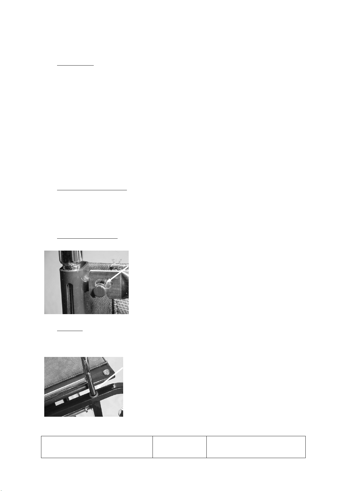
4.1.1 Backrest supports: - Make sure the locks operate positively and freely
Standing behind the wheelbase lift the backrest locking pins using the
ball shaped handgrips at the bottom of the backrest tubes. Turn them
so that they lock into the groove arrowed opposite
Lift backrest supports vertical.
Lock the supports in position by moving the handgrips out of the
arrowed groove (see photo) and making sure they have moved to the
bottom of the slot in the backrest tube.
Tendercare Ltd
Tilt and Fold Wheelbase Workshop Manual
Document No. Tilt & Fold Wheelbase workshop
manual v 2
Authority. Quality Controller
Authorised by J Adams
Page 6 of 16
September 2010
4.1.2 Push handles: - Check adjustment and security.
The push handles are fitted to the wheelbase prior to delivery. Make sure that they are in
place and that two thumbscrews are fitted to each push handle.
To adjust the height of the push handles unscrew (turn anti clockwise) the two thumbscrews
at either side and near the top of the backrest. Lift or lower the push handles to the height
required then retighten (turn clockwise) the thumbscrews.
To prevent the push handles moving in use these screws must be tight. Check tightness daily.
To make it easier for some people to push the wheelbase when the backrest is in its lowest
position the push handles can be reversed so that the handgrips are pointing forwards. Simply
unscrew the thumbscrews, turn the push handles so they are pointing forwards and refit the
thumbscrews. Take care not to get the screws cross-threaded when refitting them
4.1.3 Unfolding the wheelbase: - Check operation of folding mechanism
Standing in front of the wheelbase place palms of hands on each side of the seat rails then
press down to open the wheelbase. Take care to hold your fingers towards the centre of the
seat to avoid catching them on the wheelbase frame.
4.1.4 Backrest spreader bar: - check operation
Standing behind wheelbase lift the chrome “spreader” bar,
which is on the right hand backrest support, upwards and
place its slotted end onto the peg on the left hand backrest
support (arrowed). It may be necessary to push the backrest
supports apart when doing this.
4.1.5 Armrests: - Check fitting
Note: - Only applies when armrest is supplied as an optional extra.
Standing at the side of the wheelbase place each armrest into
the holes in the wheelbase frame. (See photo). Make sure they
are pressed into the wheelbase frame properly.
Make sure that the tube supporting the armpad extends to the
rear of the wheelbase.
To fold the wheelbase, reverse the above.
Tendercare Ltd
Tilt and Fold Wheelbase Workshop Manual
Document No. Tilt & Fold Wheelbase workshop
manual v 2
Authority. Quality Controller
Authorised by J Adams
Page 7 of 16
September 2010
4.2 Fitting and removing footrests
4.2.1 Fit the footrest: - check operation
Note: - Only applies when footrests are supplied as an optional extra.
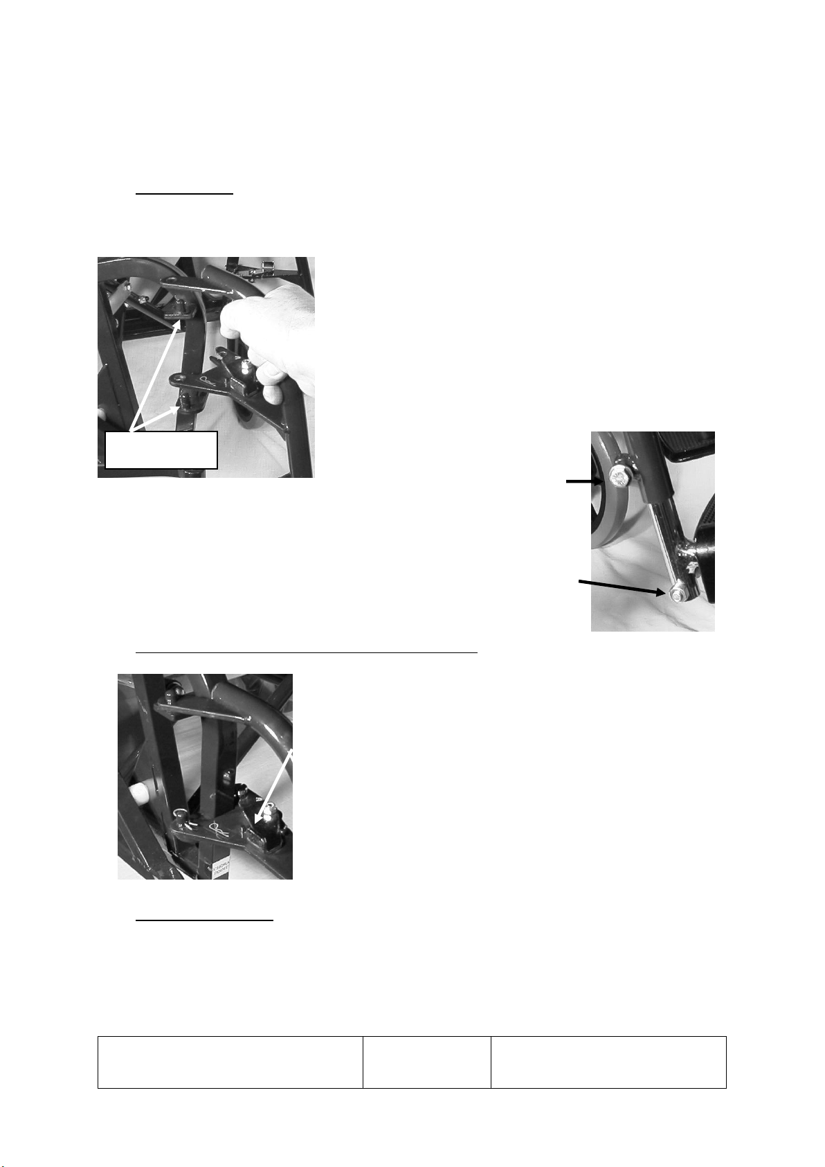
To fit the right hand footrest, stand in front of the
wheelbase. Remove the spring clip from the lower hinge
pin on the side of the wheelbase. Making sure the footplate
is facing in towards the centre of the wheelbase place the
footrest onto the hinge pins. (See Photo opposite). Replace
the spring clip. Swing the footrest towards the centre of the
wheelbase until it locks in place.
Repeat for the right hand footrest.
Adjust the height of the footrest by
loosening the nut on the support tube
using a 10 mm spanner. Move the footrest to the desired height then
retighten the clamp nut. (See picture opposite).
The angle of the footplate can be adjusted by loosening the lock nut,
which is at the bottom of the footplate support tube. Screw in or out the
footplate stop; until the desired angle is obtained then retighten the lock
nut. (See picture opposite).
4.2.2 To fold footrests back against the wheelbase frame.
Lift up the footplate so that it is vertical then push on the silver
catch on the footrest. The Footrest will then swing back. (See
picture opposite).
To return the footrest ready for use simply swing the footrest
forwards, the catch will lock automatically, and lower the
footplate.
4.2.4 To remove footrests.
Remove the spring clip from the lower hinge pin. Swing the footrest to the side and holding
the curved part of the support tube lift upwards.
Hinge Pins
Tendercare Ltd
Tilt and Fold Wheelbase Workshop Manual
Document No. Tilt & Fold Wheelbase workshop
manual v 2
Authority. Quality Controller
Authorised by J Adams
Page 8 of 16
September 2010
Note: - The spring clip prevents the footrests being lost. However, if the user needs to
regularly remove the footrests the spring clip can be discarded.
4.3 Tilt in Space
Check Tilt mechanism: - Move the seat through its full range of adjustment.
The angle of the seat and backrest can be adjusted to any angle between the upright and fully
reclined position.
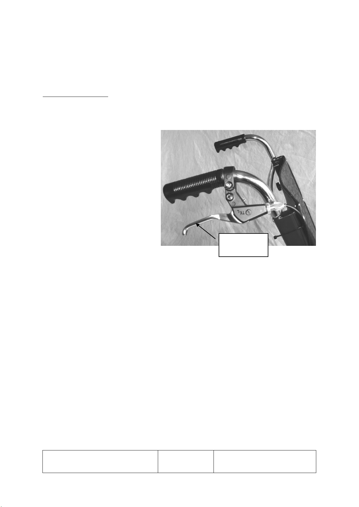
To recline the seat, put the brakes on
and stand behind the wheelbase.
Holding both push handles squeeze
the operating lever (see photo
opposite) and push down evenly on
both handles. Release the lever when
the seat is at the desired angle.
To bring the seat upright put the
brakes on and stand behind the
wheelbase. Holding both push handles
squeeze the operating lever (see photo
opposite) and lift evenly on both
handles. Release the lever when the
seat is at the desired angle.
Important: - Always hold and move both push handles together when adjusting the seat
angle.
4.4 Tyres and Brakes
The tyres do not require any attention other than being cleaned with a damp cloth when dirty.
Test brake operation by moving both levers forward as far as they will go. The wheels should
now be locked. If the wheels move the brakes need adjusting. Adjust them as instructed in
section 7.3 below.
To avoid making flat sections on the tyre never leave the brakes on for long periods i.e.
overnight or during storage.
5. Cleaning
Make sure the wheelbase is clean and well presented. If there is any dirt it should be cleaned
off using a damp cloth and then dried thoroughly.
For more stubborn stains wipe with a damp cloth using a mild solution of warm water and
soap.
Never use furniture polishes or spirit to clean the frame.
OPERATING
LEVER

Tendercare Ltd
Tilt and Fold Wheelbase Workshop Manual
Document No. Tilt & Fold Wheelbase workshop
manual v 2
Authority. Quality Controller
Authorised by J Adams
Page 9 of 16
September 2010
The Fabric parts of the Wheelchair are made from Ambla fabric. Ambla is resistant to most
mild acids, alkalis, drinks and household stains. Clean with a damp soapy cloth and rinse well
with clean water. A soft brush can be used for heavy soiling. Do not use solvents, bleaches,
abrasives, synthetic detergents, wax polishes or aerosol sprays.
6. Maintenance
Should a problem be found when carrying out the regular checks, it should be immediately
reported to the issuing authority or repairer.
6.1 Routine maintenance
The user or their family can easily carry out the following tasks. No tools are required.
1) Always wipe the wheelbase dry. Never put it away damp.
2) Check that all four push-handle retaining knobs are in place and are hand tight (daily).
3) Check brake operation (weekly).
4) Check operation of Tilt and Fold mechanism (weekly).
5) Clean frame when necessary (we suggest at least once a week).
6.2 Recommended maintenance procedure - 6 monthly
Someone who is a competent tradesman or repairer should only carry out this work. If a
major problem is found do not allow the wheelbase to be used until it has been corrected.
1) Fold and open the wheelbase. Check that all movements through the folding range are
free. Examine frame for any damage.
2) Examine nuts, bolts, pivots, sliders and frame plugs for tightness and general condition.
3) Examine push handle retaining knobs and check they are hand tight.
4) Examine footrest heel loops (If fitted) for damage or excessive wear and that the retaining
nuts are tight.
5) Examine brake assemblies for wear, damage and adjustment.
6) Examine Tilt and Fold mechanism and check operation of reclining mechanism.
7) Examine front castors and rear wheels for free rotation and security.
7. Repairs
Repairs: - for all repairs contact your issuing Authority or Tendercare Ltd.
Only an authorised repairer should carry out the following repairs.
Major repairs: - for all major repairs e.g. bent or damaged frame. The equipment should be
returned to the factory. Contact Tendercare Ltd Customer Services on telephone 01903-
726161.

Tendercare Ltd
Tilt and Fold Wheelbase Workshop Manual
Document No. Tilt & Fold Wheelbase workshop
manual v 2
Authority. Quality Controller
Authorised by J Adams
Page 10 of 16
September 2010
Factory replacement components should be used in all repairs, these are available from
Tendercare.
7.1 Front castors: - Replace the complete assembly if damaged or worn.
1) Using a 24mm spanner unscrew the hexagon nut at the top of the castor swivel until the
castor is removed.
2) Before fitting new castor apply LOCTITE thread locking compound grade 241 to the
thread on the castor stem. Screw the stem into the wheelbase mounting and tighten to
54Nm.
3) The castor should rotate under its own weight if it does not, rotate the castor forks a
number of times to ease the mechanism.
7.2 Rear Wheels: - Replace if damaged or worn.
1) Unscrew the axle retaining nut using 19mm spanners. Remove the washers and pull the
wheel assembly from the wheelbase.
2) Place the spacer taken from the old wheel onto the axle of the new wheel. Insert axle into
the wheelbase-mounting hole then fit a new 12mm friction washer onto the axle. Apply
LOCTITE thread locking compound grade 241 to the axle thread and secure with a new
M12 nut. Tighten to 45Nm. When fitted make sure the wheel rotates freely and the brakes
operate properly.
Important –Always fit new steel locking washer and nut.
7.3 Brake adjustment
The tyres are made from a solid material and do not require any attention other than being
cleaned with a damp cloth when dirty.
Test brakes by moving both brake levers forward as far as they
will go. (See Picture opposite) The wheels should now be
locked. If the wheels move the brakes need adjusting.
Adjust the brakes by loosening the nut (arrowed) locking the
brake pad in place, then turn the pad so that it is near to, but not
touching, the tyre. Retighten the locking nut.
Always adjust both brakes at the same time and recheck that the
brakes work properly.
Note: Don’t leave the brakes ON for a long period. If you do a flat section may appear on
the tyre. When not using the wheelbase i.e. overnight or during storage, make sure the brakes
are OFF.
Tendercare Ltd
Tilt and Fold Wheelbase Workshop Manual
Document No. Tilt & Fold Wheelbase workshop
manual v 2
Authority. Quality Controller
Authorised by J Adams
Page 11 of 16
September 2010
7.4 Replacing the gas struts.
The wheelbase is fitted with two gas struts one either side of the seat between the inner and
outer frame. A single lever located on the push handle and a cable linkage operates both gas
struts.
WARNING: - The gas struts are pressurised devices and therefore, are potentially
dangerous if mishandled. Do not attempt to dismantle or repair them. They
must always be replaced as a complete unit.
Important: - When removing or replacing the gas struts take care not to accidentally
operate the release lever in order to prevent the strut extending to its full
length. When fully open the gas strut length is longer than the fixing
centres and it is difficult to close them by hand.
7.4.1 Removal
1) Recline the seat to its mid position (See section 4.4).
2) Remove the operating cable from the strut by lifting it off the locating lug and fork. (see
pictures below).
3) Remove the lower mounting components using
13mm and17mm spanners. Make sure you take
note of the position of the components as you
remove them. (See sketch below).
LIFT OFF CABLE

Tendercare Ltd
Tilt and Fold Wheelbase Workshop Manual
Document No. Tilt & Fold Wheelbase workshop
manual v 2
Authority. Quality Controller
Authorised by J Adams
Page 12 of 16
September 2010
8mm Bolt
Outer Frame Nylon
Spacer Metal Guide
Inner Frame
Large Lock Nut
Gas Strut Plain Washer
M8 Nyloc Nut
LOWER MOUNTING COMPONENTS
4) Remove the upper mounting bolt using a
10mm spanner and 4mm Hexagon Key.
Make sure you take note of the position of
the components as you remove them.
Remove the gas strut from the wheelbase.
5) Loosen the locknut holding the operating
catch assembly to the shaft of the gas strut
using a 13mm spanner. Unscrew the
operating catch. (see picture opposite).
7.4.2 Re-assembly
1) Screw lock nut onto the new gas strut.
2) Screw the gas strut onto the operating lever assembly until the operating lever is almost
but not quite touching the operating pin that extends from the gas strut.
3) Tighten the lock nut against the release operating lever housing.
Tendercare Ltd
Tilt and Fold Wheelbase Workshop Manual
Document No. Tilt & Fold Wheelbase workshop
manual v 2
Authority. Quality Controller
Authorised by J Adams
Page 13 of 16
September 2010
4) Mount the gas strut following the removal instructions in reverse order.
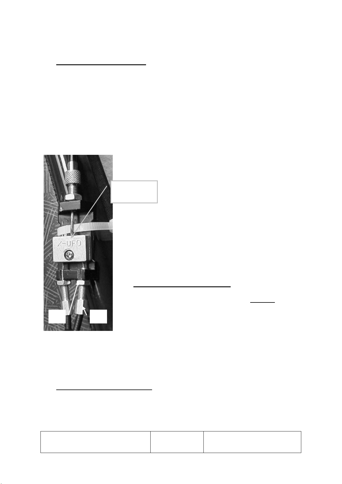
7.4.3 Adjusting the operating cables
1) The assembly consists of the hand-operated lever on the push handle, one cable leading
to an equaliser block mounted on the backrest tube and two cables leading to the two gas
struts.
2) After fitting a new gas strut always test the operation of the strut as per section 4.3 above
and if necessary adjust the operating cables.
3) The cables to individual gas struts should be adjusted first and the final adjustment made
to the single cable leading to the hand lever.
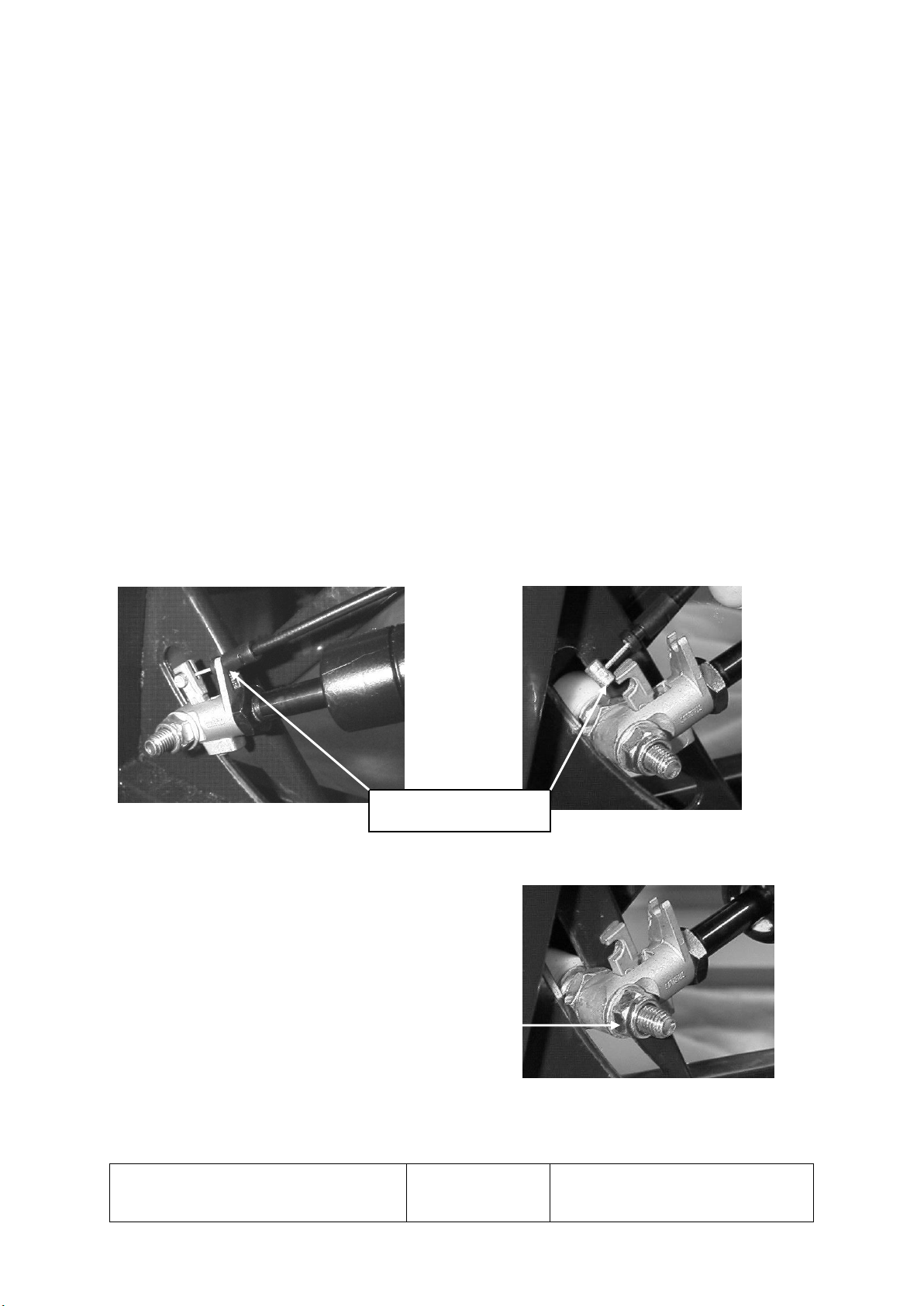
4) The cables should be adjusted so all slack is
taken up between the gas strut operating lever on
the end of the gas strut and the operating pin that
extends from the gas strut. It is important to
make sure the operating lever is just touching the
gas strut pin but not depressing it.
5) Adjust the lower cables as follows. Loosen the lock nut “A”
then turn the cable end piece “B” clockwise to loosen the
cable and anti clockwise to tighten the cable.
6) Adjust the upper cable so that all slack is taken up and the gas
strut operating lever begins to move as soon as the lever on
the push handle is squeezed.
7.4.4 Replacing lower operating cables
1) Remove cable from the gas strut. See 7.4.1 Removal above.
2) Loosen Locknut “A” (See picture opposite) and unscrew the
cable end from the equaliser bracket.
3) Using a 2.5mm Hexagon key remove the cover from the equaliser block and remove the
cable.
4) To fit the new cable, reverse the procedure.
7.4.5 Replacing upper operating cable
1. Loosen Locknut and unscrew the cable end from the equaliser bracket.
2. Using a 2.5mm Hexagon key remove the cover from the equaliser block and remove the
cable.
A
B
EQUALIZER
BLOCK

Tendercare Ltd
Tilt and Fold Wheelbase Workshop Manual
Document No. Tilt & Fold Wheelbase workshop
manual v 2
Authority. Quality Controller
Authorised by J Adams
Page 14 of 16
September 2010
3. Loosen locknut on hand lever and align slots
in the locknut and cable socket with the slot in
the handle.
4. Pull cable though slot and disconnect from the
handle.
5. To fit the new cable, reverse the procedure.
Important: - Always check the adjustment of cables after replacing them.
7.5 Replacing armpads
Note: - Only applies when armpads are supplied as an optional extra.
1) Remove armrest from the wheelbase and turn upside down.
2) Using a screwdriver remove the armpad retaining screws. Remove the armpad.
3) Hold a new armpad against the support making sure that the large overhang is towards the
outside of the armrest.
4) Insert the fixing screws and tighten.
7.6 Replacing backrest upholstery
Note: - Only applies when backrest upholstery is supplied as an optional extra.
1) Partially fold the wheelbase seat to take the pressure off the upholstery.
2) Unfasten the Hook & loop loops, one each side at the bottom of the backrest upholstery.
3) Using a screwdriver remove the eight retaining screws and washers (four each side of the
upholstery).
4) Remove the two reinforcing strips from the loops on each side of the upholstery and fit
these strips into the new upholstery.
5) Refit the upholstery to the wheelbase using the eight screws and washers. Make sure the
screws are properly tightened.
6) Pass the Hook & loop loops around the bottom of the backrest tubes and refasten on the
back of the upholstery.
8. Important Points
1) Do not reuse Nyloc nuts. Always replace with a new Nyloc nut.
2) Always use Loctite thread locking compound Grade 241.
3) Always use recommended components and parts available from Tendercare Ltd.
4) Do not modify or repair the frame
ALIGN SLOTS

Tendercare Ltd
Tilt and Fold Wheelbase Workshop Manual
Document No. Tilt & Fold Wheelbase workshop
manual v 2
Authority. Quality Controller
Authorised by J Adams
Page 15 of 16
September 2010
9. Dimensions and Weights
SEAT SIZE
380 mm (15 inch)
430 mm (17 inch)
Item
mm
mm
Overall Length
1100
1100
Overall width (inc. wheels)
630
690
Overall height
1030
1030
Length folded (ex Footrests)
900
900
Width folded
360
360
Height folded
735
735
Seat rail width
380
430
Seat rail depth
410
430
Backrest height (above seat rail)
560
560
Standard armrest height (above
seat rail)
240
240
Seat rail to footrest
370 / 450
450/370
Seat rail angle from horizontal
10° to 27°
Rear Wheel Diameter
305
305
Castor wheel diameter
200
200
Track rear
620
640
Track front
555
575
Wheel base castors trailing (rear
wheel in forward position)
540
540
Weights
kg
Total weight excluding all
detachable items
20
Footrests (both)
2.0
Armrests (both)
1.8

Tendercare Ltd
Tilt and Fold Wheelbase Workshop Manual
Document No. Tilt & Fold Wheelbase workshop
manual v 2
Authority. Quality Controller
Authorised by J Adams
Page 16 of 16
September 2010
10. Parts List
GENERAL ASSEMBLY PARTS LIST
Ref No.
Description
Qty
Part No.
SIDES; HANDED FROM REAR OF WHEELBASE
1
Outer Frame –LH
1
TTF003
2
Inner Side Frame –L/H
1
TTF004
3
Outer Side Frame –R/H
1
TTF005
4
Inner Side Frame –L/H
1
TTF006
5
Backrest Tube –L/H inc. Spring Locks
1
TTF007
6
Backrest Tube –R/H inc. Spring Locks
1
TTF008
7
Push Handles & Thumbscrews
2
TTF009
8
Push Handle Grips
2
TTF010
9
Backrest Spreader Bar
1
TTF011
10
Pantograph Assembly inc. Bushes / Spindles
1
TTF012
11
Parallel Bars (Pantograph)
2
TTF013
12
Hinge Bolts / Washers (Back Rest)
2
TTF014
13
Brake Assembly –L/H
1
TTF018
14
Brake Assembly –R/H
1
TTF019
15
Castors –Front 200NP
2
TTF020
16
Wheels –315 Pneumatic
2
TTF021
17
Wheel Spacer –Rear
2
TTF022
18
Wear Pads –Rear
2
TTF002
19
Top Pivot Bush –Nylon
2
TTF029
20
Front Tilt Location Bush –R/H
2
TTF030
21
Front Tilt Location Bush –L/H
2
TTF031
22
Brass Armrest Bushes
4
TTF054
23
Gas Spring
2
TT7740
24
Complete cable mechanism
1
TT7300
25
Backrest Locking pin
2
TTF0088
OPTIONAL EXTRAS
26
Armrest Assembly –L/H
1
TTF023
27
Armrest Assembly –R/H
1
TTF024
28
Footrest –L/H
1
TTF025
29
Footrest –R/H
1
TTF026
30
Wheelbase Footrest Hanger Mounts –R/H
1
TTF027
31
Wheelbase Footrest Hanger Mounts –L/H
1
TTF028
32
Back Canvas Insert Bars
2
TTF033
33
Armrest Pads
2
TTF001
Table of contents
Other Tendercare Wheelchair manuals

Tendercare
Tendercare Mini Tilt Wheelchair Instruction manual

Tendercare
Tendercare MINI TILT User manual

Tendercare
Tendercare MINI TILT Instruction manual

Tendercare
Tendercare Snappi Instruction manual

Tendercare
Tendercare New Aluminium Mini Tilt Wheelchair User manual

Tendercare
Tendercare Snugseat Snappi User manual

Tendercare
Tendercare GAS STRUT TILT and FOLD Wheelchair Instruction manual

Tendercare
Tendercare Snappi User manual

Tendercare
Tendercare Extra Small Fold-a-Way Spring User manual

Tendercare
Tendercare Gas Strut Model v4 User manual


