Tendercare Snappi User manual

Snappi Wheelbase & Interface User Manual
Document No: 053-01 v11 Page 1 of 35 November 2014
Snappi Wheelbase Interface User Manual.doc
Snappi
®
W
HEELBASE
A
ND
I
NTERFACE
U
SER
M
ANUAL
IMPORTANT
Please read these instructions carefully
Before using the Wheelbase or Interface

Snappi Wheelbase & Interface User Manual
Document No: 053-01 v11 Page 2 of 35 November 2014
Snappi Wheelbase Interface User Manual.doc
Fig 0.1 Wheelbase (size 1 shown)

Snappi Wheelbase & Interface User Manual
Document No: 053-01 v11 Page 3 of 35 November 2014
Snappi Wheelbase Interface User Manual.doc
Fig 0.2 Wheelbase Folded (size 1 shown)
Fig 0.3 Seat Interface (size 1 shown)

Snappi Wheelbase & Interface User Manual
Document No: 053-01 v11 Page 4 of 35 November 2014
Snappi Wheelbase Interface User Manual.doc
Fig 0.4 Interface Fitted To Frame (size 1 shown)

Snappi Wheelbase & Interface User Manual
Document No: 053-01 v11 Page 5 of 35 November 2014
Snappi Wheelbase Interface User Manual.doc
Item
Description
Page
1 Who to contact if you have difficulty 7
2 Introduction 7 – 8
3 Unpacking 9
4 Preparing the wheelbase for use 9
4.1.1 Unfolding the frame (original locks) 10 – 11
4.1.2 Unfolding the frame (Spring loaded locks) 11 – 12
4.2 Brakes & Tyres 13
4.3 Tilt in Space 14
4.4.1 Interface safety catch 15
4.4.2 Fitting the interface 16
5 Accessories 17
5.1 Shopping Basket 17
5.2 Equipment Carrying Tray 18
5.3 Sun Canopy 19 – 20
5.4 Frame Padding 20
5.5 Rain Cover 21
5.6 Vertical Cylinder Carrier 22 - 23
6 Fitting Special Seat 24
7 Final Checks 25
8 Attendant Pushing 25
8.1 Pushing 25 – 26
8.2 Brakes 26
8.3 Comfort 26
8.4 Lifting and general safety 26-27
9 Cleaning 27
10 Maintenance 27
10.1 Routine maintenance 27
10.2 Six – monthly maintenance 27 – 28

Snappi Wheelbase & Interface User Manual
Document No: 053-01 v11 Page 6 of 35 November 2014
Snappi Wheelbase Interface User Manual.doc
11 Oxygen Cylinder 29
12 Warranty 29
13 Transporting the Wheelbase 30
13.1 Preparing wheelbase for transport 30 – 32
13.2 Attaching wheelbase to vehicle 33 – 34
14 Repairs 35

Snappi Wheelbase & Interface User Manual
Document No: 053-01 v11 Page 7 of 35 November 2014
Snappi Wheelbase Interface User Manual.doc
1: Who to contact in difficulty
Tendercare Ltd.
PO BOX 3091, Littlehampton, BN16 2WF
Tel: (01903) 726161 Fax: (01903) 734083
Email: [email protected]
Web: www.tendercareltd.com
2: Introduction
The Wheelbase is made of a strong and lightweight aluminium alloy, minimising weight
and providing a very rugged frame. The wheelbase provides a tilt in space facility and has
2 fixed rear wheels and 2 castor wheels at the front for easy steering. The wheelbase
comes in two sizes with corresponding interfaces to suit a range of different seats.
The Interface provides a very lightweight, easy to operate, quick release system that can
be fitted to a wide range of special seating systems. Please note the interface requires
additional framework to fit to a seat, and has been designed to take 19mm (3/4”)
aluminium or mild steel tube.
The interface can be quickly fitted and released from the wheelbase, which can be folded
for transport. The Snappi has been successfully impact tested as a wheelbase and
interface, with the Modular and Snug seating systems. When fitting 3
rd
party seating
systems to the Snappi, the manufacturer of the system must carry out a risk assessment
before use.
These instructions apply to all sizes.
Interfacing Options:
Seat / Interface Version
Maximum Weight (Kg) Maximum Seat Width (mm)
Size 1 50 350
Size 2 50 415
IMPORTANT:
Maximum width; maximum space available for seating systems being fitted into frame.
Maximum weight includes the seat unit, occupant and all accessories.
Frame Weight:
Size 1: 10kg
Size 2: 11kg

Snappi Wheelbase & Interface User Manual
Document No: 053-01 v11 Page 8 of 35 November 2014
Snappi Wheelbase Interface User Manual.doc
Dimensions (mm)
Snappi Wheelbase Open
Size 1 Size 2
A 944 960
B 571 684
C 992 998
Dimensions (mm)
Snappi Wheelbase Folded
Size 1 Size 2
A 771 798
B 571 684
C 573 560
All sizes and weights are given as a guide. Tendercare ltd reserves the right to amend
specifications at any time as part of their product development programme.

Snappi Wheelbase & Interface User Manual
Document No: 053-01 v11 Page 9 of 35 November 2014
Snappi Wheelbase Interface User Manual.doc
3: Unpacking
The wheelbase and interface are delivered together in a cardboard carton. This measures
680mm wide x 480mm deep x 1030mm high and weighs approximately 12Kg.
WARNING:
The transit carton is quite bulky so moving and unpacking must be done with care.
Observe all lifting and handling regulations.
Stand the carton upright making sure it is supported and cannot fall over. Open the carton
and remove any packages or packing, which could obstruct the removal of the wheelbase.
Remove the wheelbase.
The carton should contain the following items:
Item Component QTY. Yes No
1 Size 1 or 2 Wheelbase 1
2 Size 1 or 2 Interface 1
3 User Manual 1
IMPORTANT:
The interface will be supplied fitted to the frame. This can easily be separated by releasing
the interface catch, once the frame has been removed from its packaging. Please refer to
section 4.4 for more information on working with the interface.
If any items are damaged or missing, then please contact Tendercare, preferably by email at
info@tendercareltd.com or alternatively please call us on (01903) 726161 within 36 hours of
delivery.
After unpacking and checking you have all components and they are in good condition
dispose of the packaging at your local recycling centre. Alternatively retain and reuse.
4: Preparing the wheelbase for use
WARNING:
When opening or folding the wheelbase, ensure that you hold the frame so that you
avoid any danger of catching your fingers in moving parts.
Keep children clear of the wheelbase during opening and folding.

Snappi Wheelbase & Interface User Manual
Document No: 053-01 v11 Page 10 of 35 November 2014
Snappi Wheelbase Interface User Manual.doc
4.1.1 Unfolding the Frame (original locks)
Standing at back of wheelbase, place
your foot on the rear crossbar X (see Fig
4.1.1.1) and lift handle labelled Y as far
as it will move.
This will open the frame.
Fig 4.1.1.1
Fig 4.1.1.2
Next locate the 2 plastic locking sliders.
These will be stowed in the “open” position
and are held in place by 2 small spring clips.
Press the 2 silver “Spring pins” in and
slide the 2 locking pieces down over the
lower tube sections.
Fig 4.1.1.3
Fig 4.1.1.4
The pins will spring through the holes in the
sliders and hold them in place (see Fig
4.1.1.4).

Snappi Wheelbase & Interface User Manual
Document No: 053-01 v11 Page 11 of 35 November 2014
Snappi Wheelbase Interface User Manual.doc
WARNING:
If the locking sliders are not in the correct position, or the spring pins do not
protrude thereby allowing the locking clips to move back up the frame, then the
frame may collapse in use.
Folding the wheelbase: To unlock the frame and fold the wheelbase, reverse the above
instructions.
4.1.2 Unfolding the Frame (Spring loaded locks)
Standing at back of wheelbase, place
your foot on the rear crossbar X (see Fig
4.1.2.1) and lift handle labelled Y as far
as it will move.
This will open the frame.
Fig 4.1.2.1
Fig 4.1.2.2
Once the frame is almost open, the 2 plastic
frame locks will engage with the angled
sections of the lower frame.
Continue to unfold the frame; this will force
the locks up the tubes. There will be some
resistance, as you will be working against the
locking springs.
Once fully open, the frame locks will
snap shut over the front frame, securing
the frame in the open position.
Always check that both locks are fully
closed. In the locked position the guide
bolt ‘B’ will be sat in the top of the slot ‘A’
on the side of the slider as shown (see
Fig 4.1.2.3). If there is any slot visible
above the guide bolt, push the lock down
by hand until it will not move any further.
Fig 4.1.2.3

Snappi Wheelbase & Interface User Manual
Document No: 053-01 v11 Page 12 of 35 November 2014
Snappi Wheelbase Interface User Manual.doc
Fig 4.1.2.4
To fold the frame:
Standing beside the frame, pull up the 2
locking sliders as shown (see Fig 4.1.2.4).
Whilst holding the locks open, push down
with your arm on the upper frame or push
handle, so that the frame starts to fold.
Release the locking sliders, and fold down
the frame by moving the push handle down
as far as it will move.
IMPORTANT:
Always check that BOTH frame locks are fully closed before using the frame. If they
are not properly engaged, the frame could collapse during use.

Snappi Wheelbase & Interface User Manual
Document No: 053-01 v11 Page 13 of 35 November 2014
Snappi Wheelbase Interface User Manual.doc
4.2 Brakes
Fig 4.2.1
To apply the brake, put your foot on the top
of brake bar ‘X’ (see Fig 4.2.1) and push
down as shown. The brake will flip down
onto the wheels and lock them.
To release the brake, simply hook your foot
between the middle raised portion of the
brake bar, and the frame crossbar. Then, lift
the brake bar with your foot until it flips back
and stops against the brake stop pins. You
may find it easier to use your hand instead
of your foot to release the brake. If
operating the brake by hand always hold the
brake by the raised section in the middle of
the bar.
Fig 4.2.2
WARNING:
The brake mechanism is spring loaded so care must be taken when operating it.
When operating the brake mechanism ensure that you always keep a firm hold of
the pushchair, keeping your hands well away from the brake mechanism.
Always put the brake on when placing the child in or taking them out of the seat.
Do not leave the pushchair on a slope, even with the brake on. Always ensure that
the pushchair is on level ground to prevent risk of injury to the occupant.
Do not leave the brake on when the pushchair is not in use as this will damage the
rear wheels.
Tyres:
As standard the Snappi wheelbase is supplied with solid tyres, however pneumatic tyres
are also available as an option. If your pushchair is supplied with pneumatic tyres these
need to be regularly checked and inflated if necessary using a hand or foot pump. The
operating pressure for the tyres is 36 PSI (note: do not inflate the tyres above 36 PSI). Do
not use high pressure air lines or mechanical pumps as used in garages to inflate the
tyres.
Snappi Wheelbase & Interface User Manual
Document No: 053-01 v11 Page 14 of 35 November 2014
Snappi Wheelbase Interface User Manual.doc
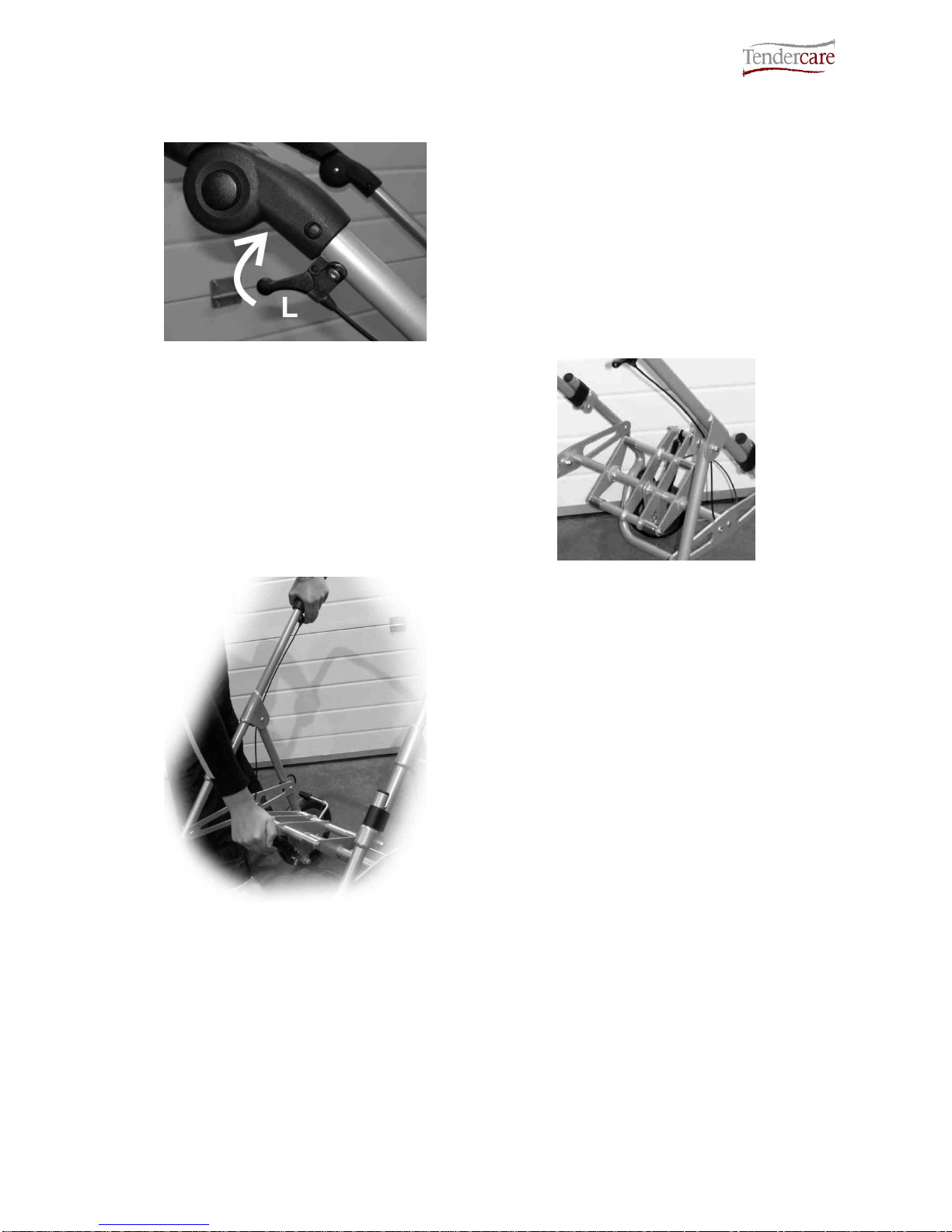
4.3 Using the Tilt in Space facility
Fig 4.3.1
To operate the tilt in space mechanism,
place your hand over the push handle
adjustor, and lift the lever ‘L’ (see Fig 4.3.1)
as shown.
This will open the gas strut and tilt the mid
section. Note; The speed of tilt can be
controlled by varying the pressure applied at
lever L.
When tilting with a seat fitted, use your
other hand to support seat as it tilts.
Fig 4.3.2
Fig 4.3.3
To reset the tilt mechanism, hold down lever
L and push down firmly on the front of the
frame interface as shown (see Fig 4.3.3).
Once the mid section is in the desired
position, release lever L. For a 90-degree
‘flat’ position, move the mid section so the
gas strut is fully closed and it will not move
any further before releasing the tilt lever.
IMPORTANT:
Always ensure any harness provided for the child is used and correctly adjusted before
reclining or returning the seat to a more upright position.
Always support the seat when tilting, as the gas springs can be quick to operate. If the seat is
not supported, is may move swiftly and could cause the occupant distress.

Snappi Wheelbase & Interface User Manual
Document No: 053-01 v11 Page 15 of 35 November 2014
Snappi Wheelbase Interface User Manual.doc
4.4.1 Interface safety catch
The interface includes a 2-stage latch that comprises a main latch and a second safety
latch that prevents accidental release of a seat from the chassis.
The safety catch must be correctly set before the main catch can be operated:
How to operate the safety catch:
Fig 4.3.1
Safety Catch Locked
The safety catch clip is located under the
front right corner of the seat near to the
release lever (See Fig 4.3.1).
Definition of components:
X: Pull handle
Y: Locking Pin
To release the safety catch, pull the handle
“X”, and turn it 90 degrees so that the pin
“Y” is fully retracted.
To lock it, pull “X” and turn 90 degrees in
the opposite direction, so that pin “Y” is fully
protruded and sits behind the interface main
catch “B” (see fig 4.3.3 on next page).
Fig 4.3.2
Safety Catch unlocked
Important:
When fitting or removing the seat, the carer / parent must first ensure that the safety
catch pin is set in the “unlocked” position. It will not be possible to fit or remove the
seat if the latch is “locked”, and attempting to do so may cause damage to the
chassis or the seat.
Once the seat has been fitted, the carer / parent must always lock the safety catch.
Note:
A warning label is positioned on the front right hand portion of the tilt frame on the
chassis, to remind carers to lock the safety catch.

Snappi Wheelbase & Interface User Manual
Document No: 053-01 v11 Page 16 of 35 November 2014
Snappi Wheelbase Interface User Manual.doc
4.4.2 Fitting the interface
To fit the interface to the frame:
Ensure the secondary latch is unlocked (as
detailed previously in section 4.4.1)
Locate the 2 rear “hooks” on the back of the
interface, over the stainless steel bushings
on the back of the frame interface.
Fig 4.4.1
Fig 4.4.2
Next, push down on the interface so that the
clips snap over the front stainless steel
bushes on the frame interface. Note that
due to the design of the frame interface, it is
not possible to fit the interface backwards. If
fitted the wrong way around the clips will not
close and it will not sit down into the frame.
Once the interface is fitted, always lock the
secondary catch as detailed in section 4.4.1
To release the interface, unlock the
secondary latch, and then lift the release
lever up as shown (See Fig 4.4.3). This will
open the clips and lift them away from the
frame in one movement. Then simply lift the
rear hooks off from the frame.
Fig 4.4.3
IMPORTANT:
Always ensure that the interface clips have latched fully. To test this, press down on the
release lever when fitted and make sure the clips will not move.
Do not attempt to fit the interface backwards. It will not lock in a rearward facing position.
Always ensure that the interface is firmly held on all 4 fixing points (the 4 stainless steel
bushes on the frame interface).
The interface is spring loaded, so ensure your fingers are clear of the clips before fitting.

Snappi Wheelbase & Interface User Manual
Document No: 053-01 v11 Page 17 of 35 November 2014
Snappi Wheelbase Interface User Manual.doc
5: Accessories
5.1: Shopping Basket
Fig 5.1.1
Fitting / removing the shopping
basket:
There are 4 hanging points
located on the insides of the
side plates (see Fig 5.1.1).
To fit the shopping basket, clip
the snap hooks on the basket
onto the 4 clipping points.
To remove the shopping
basket, unclip the 4 hooks.
The shopping basket includes
an expandable section at the
back to help with loading of
bulky items. To expand the
basket, peel apart the Velcro at
the back to release the extra
material.
Important:
•Always check that the shopping basket is securely fitted before use.
•The maximum carrying load for the shopping basket is 3kg.
•Always ensure that the total load of the occupant, seat and accessories does not
exceed the maximum carry limit stated for the wheelbase (see section 1 of this
manual).
•The shopping basket may remain fitted when folding the wheelbase.
•All contents must be removed from the shopping basket before folding the
wheelbase.
•The contents of the shopping basket must be removed when using the wheelbase
as a seat in a motor vehicle.

Snappi Wheelbase & Interface User Manual
Document No: 053-01 v11 Page 18 of 35 November 2014
Snappi Wheelbase Interface User Manual.doc
5.2: Equipment Carrying Tray
To Fit the equipment carrying tray:
The equipment-carrying tray has 2 sets of
fixing points on its underside to secure it to
the chassis (see Fig 5.2.1).
Feed the tray under the wheelbase from the
front of the chassis and hook the rear points
‘A’ under the rear cross bar, ensuring that
the tray is in the middle so it sits in-between
the vertical brake bars.
Next, with the front turn catch ‘B’ rotated out
of the way; rotate the tray down so it sits on
the front cross bar.
Finally turn the front catch ‘B’ 90 degrees so
it sits under the front cross bar (this catch
may be quite tight).
Fig 5.2.1
Fig 5.2.2
To remove the tray, unlock catch B, lift up
and remove the tray from the chassis.
Important:
•Always ensure the equipment-
carrying tray is securely fitted before
use.
•The maximum carrying load for the
equipment-carrying tray is 25kg.
•Always ensure that the total load of
the occupant, seat and accessories
does not exceed the maximum carry
limit stated for the wheelbase (see
section 1 of this manual).
•The equipment-carrying tray must be
removed before folding the chassis.
•The equipment-carrying tray must be
removed when using the wheelbase
as a seat in a motor vehicle.

Snappi Wheelbase & Interface User Manual
Document No: 053-01 v11 Page 19 of 35 November 2014
Snappi Wheelbase Interface User Manual.doc
5.3: Sun Canopy
There are 2 styles of sun canopy available for the Snappi Wheelbase; the ‘Classic Style’
and the ‘Umbrella Style’.
To fit the Classic Style sun canopy:
First unfold the sun canopy.
Then clip the 2 fixing brackets onto the
frame (see arrows, right), so that the top
clip sits in the desired position.
The sun canopy can then by angled to
the desired position.
To remove the sun canopy, simply
unscrew the clips.
(*Seat shown in Fig 5.3.1 is for
illustration purposes only.)
Important:
•You must remove the sun
canopy before folding the frame.
•You must remove the sun
canopy when using the
wheelbase as a seat in a motor
vehicle.
Fig 5.3.1*
To fit the Umbrella Style sun canopy:
Fig 5.3.2
Remove the umbrella from its protective
sleeve.
Next, unclip the frame fixing from the
umbrella by pressing on the button and
pulling apart as shown (See Fig 5.3.2).
Brackets

Snappi Wheelbase & Interface User Manual
Document No: 053-01 v11 Page 20 of 35 November 2014
Snappi Wheelbase Interface User Manual.doc
Next, unscrew the frame mounting to open
the jaws until it will fit over the frame.
Position the mounting onto the upper frame
tube (see fig 5.3.4 below).
Adjust the angle of the clip so that it is
vertical.
Fig 5.3.3
Fig 5.3.4
When in the desired position, retighten the
screw to lock it onto the frame
Finally, clip the umbrella section back onto
the mounting by pushing the 2 halves of
the clip back together, and open the
umbrella.
If a different angle is needed, simply loosen
the locking screw, move to the required
angle and retighten.
Important:
•You must remove the umbrella
section before folding the frame (the
frame mounting clip can be left in
place).
•The entire sun umbrella must be
removed when using the wheelbase
as a seat in a motor vehicle.
5.4: Frame Padding
Fig 5.4.1
To fit frame padding, wrap around the
section of framework to be padded, and
clip the snap fasteners together(See Fig
5.5.1)Repeat on the other side.
If you are fitting a rain cover as well as the
frame padding, it is important that you fit
the rain cover to the pushchair first and
then fit the frame padding round it. Finally
join the rear flap of material to the sides of
the rain cover with the Velcro tabs.
Other manuals for Snappi
2
This manual suits for next models
1
Table of contents
Other Tendercare Wheelchair manuals

Tendercare
Tendercare Extra Small Fold-a-Way Spring User manual

Tendercare
Tendercare TILT and FOLD Instruction manual

Tendercare
Tendercare Extra Small Fold-a-Way Spring Instruction manual

Tendercare
Tendercare Mini Tilt Wheelchair User manual

Tendercare
Tendercare Gas Strut Model v4 User manual

Tendercare
Tendercare Mini Tilt Wheelchair Instruction manual

Tendercare
Tendercare Snugseat Snappi User manual

Tendercare
Tendercare GAS STRUT TILT and FOLD Wheelchair Instruction manual

Tendercare
Tendercare New Aluminium Mini Tilt Wheelchair User manual

Tendercare
Tendercare Mobility Nursery Snugseat Spring User manual


