manuals.online logo
Brands
  1. Home
  2. •
  3. Brands
  4. •
  5. Tennant
  6. •
  7. Blower
  8. •
  9. Tennant 6100 Training manual

Tennant 6100 Training manual

IB 340763 (11-2005) 1
No. 340763
Machine: 6100/6100E/
7100/EZ Rider/7080
Published: 11-2005
Rev. 01
INSTRUCTION BULLETIN
NOTE: DO NOT DISCARD the Parts List from the Instruction Bulletin. Place the
Parts List in the appropriate place in the machine manual for future
reference. Retaining the Parts List will make it easier to reorder
individual parts and will save the cost of ordering an entire kit.
NOTE:Numbers in parenthesis ( ) are reference numbers for parts listed in Bill of Materials.
Installation instructions for kit number 377411
SYNOPSIS / PROBLEM:
This kit contains the parts needed to replace the brake linkage on 6100, 7100, and EZ Rider
machines.
Please follow step-by-step instructions.
SPECIAL TOOLS / CONSIDERATIONS: Floor jack or chain hoist
(Estimated time to complete: 2 hours)
PREPARATION:
1. Park the machine on a clean level surface.
2. Turn off machine, remove key, and set
parking brake.
FOR SAFETY: Before leaving or servicing
machine, stop on level surface, set parking
brake, turn off machine, and remove key.
3. Disconnect the battery cables from the
batteries.
WARNING: Always disconnect battery
cables from machine before working on
electrical components.
4. Block the rear wheels of the machine.
FOR SAFETY: When servicing machine, block
machine tires before jacking up machine.
5. Use a jack to raise the front end of the
machine. Refer to Operators Manual for more
information about safely jacking up the
machine.
FOR SAFETY: When servicing machine, use a
hoist or jack that will support the weight of
the machine.
FOR SAFETY: When servicing machine, jack
machine up at designated locations only.
Support the machine with jack stands.
INSTALLATION:
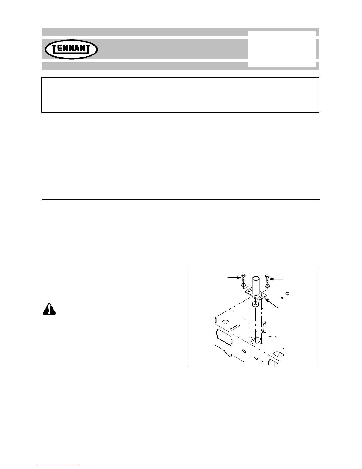
1. Loosen both hex screws securing the steering
assembly housing to the machine frame.
Refer to Fig. 1.
Loosen Loosen
Slide entire
assembly
towardsrear
of machine
FIG. 1
2. Slide the steering assembly housing toward
the rear of the machine to loosen the steering
chain tension.
IB 340763 (11-2005)2
3. Remove the master link from the steering
chain and remove the steering chain from the
machine. Refer to Fig. 2.
FIG. 2
4. Remove the cotter pin securing the brake link
to the brake arm and remove the brake link
from the side of the drive assembly. Set aside
all loose parts. Refer to Fig. 3 or Fig. 4.
Cotter
Pin
Brake Link
FIG. 3--Older Machines
Brake
Link
Cotter
Pin
FIG. 4--Newer Machines
5. Remove the power wire cover from the side of
the drive assembly. Refer to Fig. 4.
FIG. 5
6. Mark the locations of the wires connected to
the drive assembly and then disconnect the
wires from the assembly. Set aside all loose
parts. Refer to Fig. 6.
FIG. 6
7. Remove the cable clamp and pull the cable
out from the duct sleeve. Set aside all loose
parts. Refer to Fig. 7.
FIG. 7
IB 340763 (11-2005) 3
8. Remove the hardware (A) securing the brake
pedal assembly (B) to the machine. Set aside
all loose parts. Refer to Fig. 8.
A
B
D
G
E
F
FIG. 8
9. Remove the clevis pin (E), cotter pin (F), and
washers (G) from the brake pedal assembly
(A). Set aside all loose parts. Refer to Fig. 8.
10. Disconnect the extension spring (D) from the
brake pedal assembly (A). Set aside all loose
parts. Refer to Fig. 8.
11. Remove the clevis pin (H) and cotter pin (J)
from the brake mounting channel (K) and
remove the brake mounting channel from the
machine. Set aside the cotter pin. Discard the
clevis pin. Refer to Fig. 9.
L
H
J
K
M
N
P
1
FIG. 9
12. Remove the bolts (L) and hex nuts (M)
securing the spring mounting channel (N) and
compression spring (P) to the brake mounting
channel (K). Discard the brake mounting
channel. Set aside the remaining parts. Refer
to Fig. 9.
13. Use the bolts (L) and hex nuts (M) to install
the compression spring (P) and spring
mounting channel (N) onto the new brake
mounting channel (1). Refer to Fig. 9.
14. Place a jack or blocks underneath the front
drive assembly to support the assembly.
15. Remove the four button screws (Q) holding
the front drive assembly to the machine and
carefully remove the drive assembly from
under the machine. Refer to Fig. 10.
Q
FIG. 10
16. Remove the cotter pin (R) and clevis pin (S)
securing the left and right brake arms (T) to
the upper brake link (U). Set aside the cotter
pin and clevis pin. Refer to Fig. 11 and Fig.
12.
R
S
T
U
U
V
2
3
FIG. 11--Older Machines
IB 340763 (11-2005)4
U
T
R
S
U
V
2
3
FIG. 12--Newer Machines
17. Remove the upper brake link (U) and brake
channel (V) from the lower drive assembly.
Discard the upper brake link and brake
channel. Refer to Fig. 11 and Fig. 12.
18. Slide the brake channel (3) onto the brake link
(2). Refer to Fig. 11 and Fig. 12.
19. Insert the brake link (2) into the lower drive
assembly. Refer to Fig. 11 and Fig. 12.
20. Use clevis pin (R) and cotter pin (S) to
secure the brake link (2) to the left and right
brake arms (T). Refer to Fig. 11 and Fig. 12.
21. Use a floor jack to position the front drive
assembly underneath the machine.
22. Use the button screws (Q) to reinstall the
front drive assembly onto the machine.
Refer to Fig. 13.
Q
FIG. 13
23. Use the master link to reinstall the steering
chain onto the machine. Refer to Fig. 14.
FIG. 14
24. Push the steering housing forward in the slots
and tighten the hex screws to 37--48Nm
(26--34 ft. lbs). Refer to Fig. 15.
Tighten
Slide
entire
assembly
forward
Tighten
FIG. 15
25. Use clevis pin (4) and cotter pin (5) to mount
the brake mounting channel (1) assembly to
the brake channel (3). Refer to Fig. 16.
L
H
J
K
M
N
P
1
3
4
5
FIG. 16
IB 340763 (11-2005) 5
26. Use hardware (A) to reinstall the brake
pedal assembly (B) onto the machine. Refer
to Fig. 17.
A
B
D
G
E
F
FIG. 17
27. Use cotter pin (F), clevis pin (E), and washers
(G) to attach the brake pedal assembly (B) to
the machine. Refer to Fig. 17.
28. Connect the extension spring (D) from the
brake pedal assembly (A). Refer to Fig. 17.
29. Pull the cable through the duct sleeve and
reinstall the cable clamp on the machine
Refer to Fig. 18.
FIG. 18
30. Reconnect the wires to the drive motor. Refer
to Fig. 19.
FIG. 19
31. Reinstall the power wire cover onto the side of
the drive assembly. Refer to Fig. 20.
FIG. 20
32. Reinstall the brake link onto the side of the
drive assembly and reinstall the cotter pin to
secure the brake link onto the drive assembly.
Refer to Fig. 21 or Fig. 22.
Cotter
Pin
Brake Link
FIG. 21--Older Machines
IB 340763 (11-2005)6
Brake
Link
Cotter
Pin
FIG. 22--Newer Machines
33. Lower the machine to the floor and remove
the jack from underneath the machine.
34. Reconnect the battery cables to the batteries.
35. Test the machine. Check the front drive for
proper operation.
Bill of Materials for Kit, Repmt, Brake Linkage--377411
Ref.
Tennant
Part No. Description Qty.
o377411 )Kit, Repmt, Brake Linkage 1
Y1 1019764 Bracket, Channel, Mtg, Brake 1
Y2 1026028 Link, Brake, Upper 1
Y3 1026017 Channel, Brake [6100] 1
Y4 29558 Pin, Clevis, 0.37 D X 1.50L 1
Y539005 )Pin, Cotter, .094 X 0.75 1
TENNANT COMPANY
P. O. Box 1452
Minneapolis, MN 55440-1452

Other manuals for 6100

5

This manual suits for next models

4

Other Tennant Blower manuals

Tennant 810 LPG User manual

Tennant

Tennant 810 LPG User manual

Tennant 250 Product manual

Tennant

Tennant 250 Product manual

Tennant S5 User manual

Tennant

Tennant S5 User manual

Tennant 3640E User manual

Tennant

Tennant 3640E User manual

Tennant 140 Product manual

Tennant

Tennant 140 Product manual

Tennant S7 User manual

Tennant

Tennant S7 User manual

Tennant 6500 Training manual

Tennant

Tennant 6500 Training manual

Tennant S5 NA Product manual

Tennant

Tennant S5 NA Product manual

Tennant 800 User manual

Tennant

Tennant 800 User manual

Tennant S30 User manual

Tennant

Tennant S30 User manual

Tennant S6 NA User manual

Tennant

Tennant S6 NA User manual

Tennant 6100 Training manual

Tennant

Tennant 6100 Training manual

Tennant 285 User manual

Tennant

Tennant 285 User manual

Tennant 6100 User manual

Tennant

Tennant 6100 User manual

Tennant 800 User manual

Tennant

Tennant 800 User manual

Tennant SweepSmart S20 ELECTRIC User manual

Tennant

Tennant SweepSmart S20 ELECTRIC User manual

Tennant S20 Gas User manual

Tennant

Tennant S20 Gas User manual

Tennant S8 User manual

Tennant

Tennant S8 User manual

Tennant S3 Product manual

Tennant

Tennant S3 Product manual

Tennant CENTURION User manual

Tennant

Tennant CENTURION User manual

Tennant sentinel User manual

Tennant

Tennant sentinel User manual

Tennant 3640G/LP User manual

Tennant

Tennant 3640G/LP User manual

Tennant S6 User manual

Tennant

Tennant S6 User manual

Tennant 6550 User manual

Tennant

Tennant 6550 User manual

Popular Blower manuals by other brands

SNOWJOE SUNJOE 24V-WSB-LTE Operator's manual

SNOWJOE

SNOWJOE SUNJOE 24V-WSB-LTE Operator's manual

Homelite ut09526 Operator's manual

Homelite

Homelite ut09526 Operator's manual

GreenWorks 24022 Operator's manual

GreenWorks

GreenWorks 24022 Operator's manual

Craftsman 358.797921 Operator's manual

Craftsman

Craftsman 358.797921 Operator's manual

Powr-Flite PIRANHA PS 400 manual

Powr-Flite

Powr-Flite PIRANHA PS 400 manual

Parkside PLS 2600 A1 Translation of the original instructions

Parkside

Parkside PLS 2600 A1 Translation of the original instructions

Weed Eater 545146904 instruction manual

Weed Eater

Weed Eater 545146904 instruction manual

Sweepster VRS Series manual

Sweepster

Sweepster VRS Series manual

Stihl BGA 85 instruction manual

Stihl

Stihl BGA 85 instruction manual

Worx MAKER X WX747L manual

Worx

Worx MAKER X WX747L manual

SSP MUB103 instruction manual

SSP

SSP MUB103 instruction manual

TURFCO Torrent Operators manual & parts lists

TURFCO

TURFCO Torrent Operators manual & parts lists

RCm Atom H Use and maintenance manual

RCm

RCm Atom H Use and maintenance manual

Echo PB-413H - 02-09 Operator's manual

Echo

Echo PB-413H - 02-09 Operator's manual

Zenoah HBZ2600 Operator's manual

Zenoah

Zenoah HBZ2600 Operator's manual

Graphite 58G031 Translation of the original instructions

Graphite

Graphite 58G031 Translation of the original instructions

Maruyama MD830 Owner's/operator's manual

Maruyama

Maruyama MD830 Owner's/operator's manual

Makita DUB361Z instruction manual

Makita

Makita DUB361Z instruction manual

manuals.online logo
manuals.online logoBrands
  • About & Mission
  • Contact us
  • Privacy Policy
  • Terms and Conditions

Copyright 2025 Manuals.Online. All Rights Reserved.