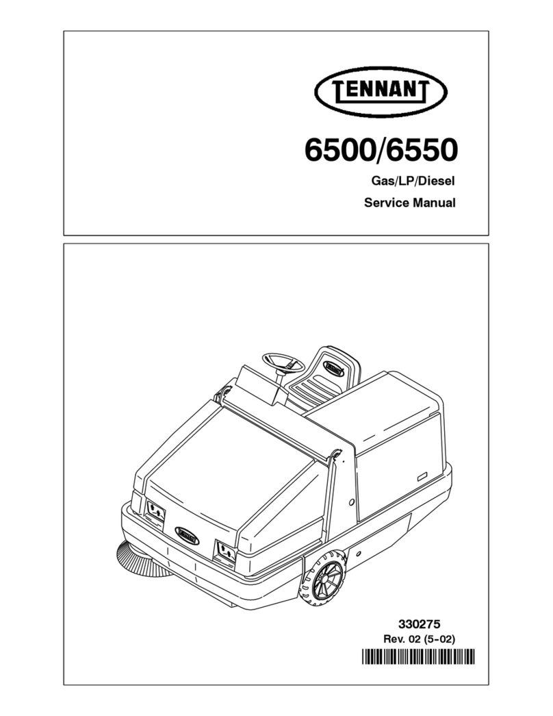
Tennant sentinel User manual

*331009*
331009
Rev. 09 (3-2015)
Sweeper
English EN
Operator Manual
SENTINELR
For latest Parts manual or other
language Operator manual, visit:
www.tennantco.com/manuals
TennantTrueRParts

INTRODUCTION
This manual is furnished with each new model. It provides necessary operation and maintenance instructions.
Read this manual completely and understand
the machine before operating or servicing it.
This machine will provide excellent service. However, the best results will be obtained at minimum costs if:
The machine is operated with reasonable care.
The machine is maintained regularly - per the machine maintenance instructions provided.
The machine is maintained with manufacturer supplied or equivalent parts.
PROTECT THE ENVIRONMENT
Please dispose of packaging materials,
used components such as batteries
and fluids in an environmentally safe
way according to local waste disposal
regulations.
Always remember to recycle.
Model No. −
Serial No. −
Installation Date −
Please fill out at time of installation for future
reference.
MACHINE DATA
DECLARATION OF CONFORMITY FOR MACHINERY
(according to Annex II A of the Machinery Directive)
TENNANT N.V.
Industrielaan 6 5405 AB
P.O. Box 6 5400 AA
Uden −The Netherlands
Uden, 21−05−2010
EN
Herewith declares, on our own responsibility, that the machinery
SENTINEL
−is in conformity with the provisions of the Machinery Directive (2006/42/EC), as amended and with national
implementing legislation
−is in conformity with the provisions of the Electro Magnetic Compatibility Directive 2004/108/EC
−is in conformity with the provisions concerning noise emission for outdoor use (Directive 2000/14/CE) and
with national implementing legislation −Lwa = 108 dB(A) Average & Lwa = 110 dB(A) Guaranteed
and that
−the following harmonized standards or parts of these standards have been applied: EN ISO 14121−1, EN
1037, EN 60335−1, EN 60204−1, EN ISO 13849−1, EN ISO 13849−2, EN 60529, EN ISO 4413, EN 349, EN
55012, EN 61000−6−2, EN ISO 11201, EN ISO 4871, EN ISO 3744*, EN ISO 13059*, EN ISO 3450, EN
60335−2−72.
−the following national standards or parts of these standards have been used:
Tennant N.V.
Industrielaan 6 5405 AB
P.O. Box 6 5400 AA Uden−The Netherlands
www.tennantco.com
Specificationsand parts are subject to change without notice.
Original instructions, Copyright 2003, 2004, 2006 −2010, 2013, 2015 TENNANT, Printed in U.S.A.

CONTENTS
1
Sentinel331009 (5−10)
CONTENTS
Page
SAFETY PRECAUTIONS 4................
OPERATION 8...........................
OPERATOR RESPONSIBILITY 8........
MACHINE COMPONENTS 9............
CONTROL PANEL SYMBOLS 10.........
CONTROLS AND INSTRUMENTS 12.....
OPERATION OF CONTROLS 17.........
OPERATOR SEAT 17.................
SEAT BELTS 17.....................
STEERING WHEEL 18...............
STEERING WHEEL TILT LEVER
(For machines serial number 007053
and below) 18....................
STEERING WHEEL TILT LEVER
(For machines serial number 007054
and above) 18....................
PARKING LIGHTS, HEADLIGHTS,
BRIGHT HEADLIGHTS, SIGNAL,
AND HORN SWITCH 19........
WINDSHIELD WIPER AND WASHER
SWITCH 19.......................
IGNITION SWITCH
(For machines serial number 007709
and below) 20....................
IGNITION SWITCH
(For machines serial number 007710
and above) 20....................
PROPELLING PEDAL 20.............
BRAKE PEDAL 21...................
ACCESSORY POWER SOCKET 21....
DIRECTIONAL LEVER 21.............
THROTTLE LEVER 22................
VARIO SWEEPING BRUSH
LOCK PIN (OPTION) 22...........
VARIO SWEEPING BRUSH
TILT/ARM SWITCH (OPTION) 22...
VARIO SWEEPING BRUSH
JOYSTICK (OPTION) 23...........
VARIO SWEEPING BRUSH
ON−OFF SWITCH (OPTION) 24....
VARIO SWEEPING BRUSH
RAISE/LOWER SWITCH (OPTION) 24.
BRIGHT HEADLIGHTS LIGHT 25......
PARKING BRAKE LIGHT 25...........
SIGNAL LIGHT 25...................
GLOW PLUG LIGHT 26...............
CLOGGED ENGINE
AIR FILTER LIGHT 26.............
WATER TANK LOW LIGHT (OPTION) 26
VACUUM WAND
DOOR LIGHT (OPTION) 27........
HOPPER OVERLOAD LIGHT 27.......
HEATER KNOB 27...................
FAN KNOB 28.......................
AIR CONDITIONER KNOB (OPTION) 28
Page
AIR CIRCULATION VENTS 28.........
LOW BRAKE PRESSURE LIGHT 29...
INCLINE LIGHT (High Dump Model) 29.
ENGINE SHUTDOWN
OVERRIDE SWITCH 30............
PARKING BRAKE SWITCH 30.........
LEFT SIDE BRUSH
WATER VALVE KNOB (OPTION) 31.
VARIO SWEEPING BRUSH LEFT
WATER VALVE KNOB (OPTION) 31.
VARIO SWEEPING BRUSH RIGHT
WATER VALVE KNOB (OPTION) 32.
RIGHT SIDE BRUSH
WATER VALVE KNOB (OPTION) 32.
FUSES 33...........................
ENGINE WATER TEMPERATURE
GAUGE 34.......................
FUEL LEVEL GAUGE 34..............
ENGINE OIL PRESSURE GAUGE 34..
VOLTMETER 35.....................
HOURMETER 35....................
ODOMETER 35......................
SPEEDOMETER 35..................
TACHOMETER 36...................
SWITCH PANEL 37..................
HOPPER TILT BACK SWITCH 37......
HOPPER TILT FORWARD SWITCH 37.
HOPPER LIFT SWITCH
(High Dump Model) 38.............
HOPPER LOWER SWITCH
(High Dump Model) 38.............
HOPPER DOOR OPEN SWITCH 39....
HOPPER DOOR CLOSE SWITCH 39..
WATER PUMP SWITCH (OPTION) 39..
LEFT SIDE BRUSH SWITCH
(OPTION) 40.....................
RIGHT SIDE BRUSH SWITCH 40......
FILTER SHAKER SWITCH 40.........
CONVEYOR REVERSE SWITCH 41...
VACUUM FAN SWITCH 41............
SWEEP SWITCH 42..................
4-WAY WARNING LIGHTS SWITCH 43.
HAZARD LIGHT SWITCH 43..........
SIDE BRUSH SPOT LIGHT(S)
SWITCH 43.......................
REAR NIGHT SWEEPING
LIGHT SWITCH (OPTION) 44......
FRONT NIGHT SWEEPING
LIGHT SWITCH (OPTION) 44......
HIGH PRESSURE WASHER
SWITCH (OPTION) 44.............
DOME AND MAP LIGHT SWITCH 45...

CONTENTS
Sentinel331009 (5−10)
2
Page
RADIO AND COMPACT DISK PLAYER
(OPTION) 45.....................
LATCHES 45........................
TRAFFIC ADVISOR SIGNAL LIGHT
SWITCH (OPTION) 46.............
TRAFFIC ADVISOR SIGNAL LIGHT
FUNCTION KNOB (OPTION) 46....
HOPPER SUPPORT PIN 47...........
HOPPER SUPPORT BAR
(High Dump Model) 48.............
HOW THE MACHINE WORKS 49.........
PRE-OPERATION CHECKLIST 50........
STARTING THE MACHINE 51............
SWEEPING AND BRUSH
INFORMATION 54...................
SWEEPING 55.........................
STOP SWEEPING 59...................
EMPTYING THE HOPPER 61............
STOP THE MACHINE 65................
POST-OPERATION CHECKLIST 67.......
ENGAGING HOPPER SUPPORT PIN 68..
DISENGAGING HOPPER
SUPPORT PIN 70....................
ENGAGING HOPPER SUPPORT BAR
(High Dump Model) 71................
DISENGAGING HOPPER SUPPORT BAR
(High Dump Model) 73................
OPERATION ON INCLINES 74...........
OPTIONS 75...........................
VARIO SWEEPING BRUSH 75........
WET DUST CONTROL SYSTEM 77....
VACUUM WAND 79..................
CAB JACK 82........................
TILTING THE CAB (MANUALLY) 84....
MACHINE TROUBLESHOOTING 86......
MAINTENANCE 88........................
MAINTENANCE CHART 89..............
LUBRICATION 91.......................
A. HOPPER TILT (LOW DUMP) 92....
B. HOPPER LIFT/TILT
(HIGH DUMP OPTION) 92.........
C. AXLE LEAF SPRINGS 92..........
D. STEERING CYLINDER 93.........
E. WHEEL PIVOTS POINTS 93.......
F. SIDE BRUSH PIVOT 93............
G. VARIO SWEEPING BRUSH
(OPTION) 94.....................
H. CONVEYOR BEARINGS 94........
I. CONVEYOR CHAIN 95.............
J. ENGINE 95.......................
K. DIFFERENTIAL 96................
L. MAIN BRUSH SUPPORT RODS 96.
HYDRAULICS 97.......................
HYDRAULIC FLUID RESERVOIR 97...
REPLACING HYDRAULIC FLUID
FILTER 98........................
HYDRAULIC FLUID 99...............
HYDRAULIC HOSES 100..............
PURGING AIR FROM THE
HYDRAULIC CONVEYOR LIFT
SYSTEM 100...................
Page
ENGINE 101............................
COOLING SYSTEM 101...............
AIR FILTER 102.......................
AIR INTAKE SCREEN 103.............
FUEL FILTER 103.....................
FUEL WATER SEPARATOR 103........
FUEL LINES 104......................
ENGINE VALVE 104......................
CAB FILTERS 105.......................
WET DUST CONTROL FILTER
(OPTION) 105........................
WINDSHIELD WIPER BLADES 106........
WINDSHIELD WASHER FLUID 106........
BATTERY 106...........................
BELTS AND CHAINS 107.................
ALTERNATOR/FAN BELTS 107.........
AIR CONDITIONER BELT (OPTION) 107
STATIC DRAG CHAIN 107.............
DEBRIS HOPPER 108....................
HOPPER DUST FILTER 108............
TO CLEAN THE HOPPER
DUST FILTER 108..................
TO REMOVE OR REPLACE HOPPER
DUST FILTER 108..................
THERMO SENTRY 109................
CONVEYOR 110.........................
BRUSHES 111...........................
MAIN BRUSH 111.....................
TO REPLACE MAIN BRUSH 111.....
TO CHECK AND ADJUST MAIN
BRUSH PATTERN 114...........
SIDE BRUSH 115.....................
TO REPLACE SIDE BRUSH 115.....
SKIRTS AND SEALS 116.................
BRUSH ACCESS DOOR SKIRTS 116...
DRY DUST CONTROL SKIRTS
(OPTION) 116.....................
BRUSH COMPARTMENT REAR
SKIRT 116.........................
CONVEYOR SKIRTS 117..............
DOOR SEALS 117....................
CONVEYOR SEALS 118...............
HOPPER SEALS 118..................
SKIDS 119.
BRAKES AND TIRES 119.................
SERVICE BRAKES 119................
PARKING BRAKE 119.................
TIRES 120...........................
WHEEL ALIGNMENT 120..............
WHEEL NUTS 120....................
PUSHING, TOWING, AND
TRANSPORTING THE MACHINE 121...
PUSHING OR TOWING THE
MACHINE 121.....................
TRANSPORTING THE MACHINE 122...
MACHINE JACKING 124..................
STORING MACHINE 125.................
FREEZE PROTECTION FOR WET
DUST CONTROL SYSTEM 125......
FREEZE PROTECTION FOR THE
HIGH PRESSURE WASHER
OPTION 125....................
CONTENTS
3
Sentinel331009 (5−10)
Page
SPECIFICATIONS 126......................

GENERAL MACHINE
DIMENSIONS/CAPACITIES 126........
GENERAL MACHINE PERFORMANCE 126.
POWER TYPE 127.......................
STEERING 128..........................
HYDRAULIC SYSTEM 128................
BRAKING SYSTEM 128..................
TIRES 128..............................
MACHINE DIMENSIONS 129..............

SAFETY PRECAUTIONS
Sentinel331009 (12−09)
4
SAFETY PRECAUTIONS
The following precautions are used throughout
this manual as indicated in their description:
WARNING: To warn of hazards or unsafe
practices which could result in severe
personal injury or death.
FOR SAFETY: To identify actions which
must be followed for safe operation of
equipment.
The machine is suited to sweep disposable debris.
Do not use the machine other than described in
this Operator Manual.
The following information signals potentially
dangerous conditions to the operator or
equipment:
WARNING: Machine can emit excessive
noise. Consult with your regulatory
agency for exposure limits. Hearing loss
can result. Wear hearing protection.
WARNING: Raised hopper may fall.
Engage hopper support bar.
WARNING: Raised hopper may fall.
Engage hopper support pin.
WARNING: Brush linkage pinch points.
Stay clear when linkage is moving.
WARNING: Side brush can move. Do
not step on side brush.
WARNING: Hopper door pinch point.
Stay clear of hopper door.
WARNING: High dump vertical
clearance. Stay clear of overhead
obstructions and power lines.
WARNING: Conveyor throws debris.
Conveyor pinch point. Stay clear when
in operation.
WARNING: Flammable materials can
cause explosion or fire. Do not use
flammable materials in tank. Only use
water.
WARNING: Engine emits toxic gases.
Severe respiratory damage or
asphyxiation can result. Provide
adequate ventilation. Consult with your
regulatory agency for exposure limits.
Keep engine properly tuned.
WARNING: Lift arm pinch point. Stay
clear of hopper lift arms.
WARNING: Raised cab may fall. Engage
cab support bar.
WARNING: Do not spray people or
animals. Severe personal injury can
result. Wear eye protection. Hold
sprayer with two hands.
FOR SAFETY:
1. Do not operate machine:
−Unless trained and authorized.
−Unless operation manual is read and
understood.
−In flammable or explosive areas unless
designed for use in those areas.
2. Before starting machine:
−Check for fuel leaks.
−Keep sparks and open flame away
from refueling area.
−Make sure all safety devices are in
place and operate properly.
−Check brakes and steering for proper
operation.
3. When starting machine:
−Keep foot on brake and directional
pedal in neutral.
4. When using machine:
−Do not pick up burning or smoking
debris, such as cigarettes, matches or
hot ashes.
−Use brakes to stop machine.
−Go slow on inclines and slippery
surfaces.
−Use care when reversing machine.
−Move machine with care when hopper
is raised.
−Only dump the hopper on a level
surface.
−Make sure adequate clearance is
available before raising hopper.
−Do not carry riders on machine.
−Always follow safety and traffic rules.
−Report machine damage or faulty
operation immediately.
5. Before leaving or servicing machine:
−Stop on level surface.
−Set parking brake.
−Turn off machine and remove key.

SAFETY PRECAUTIONS
5
Sentinel331009 (9−03)
6. When servicing machine:
−Avoid moving parts. do not wear loose
jackets, shirts, or sleeves.
−Block machine tires before jacking
machine up.
−Jack machine up at designated
locations only. Block machine up with
jack stands.
−Use hoist or jack that will support the
weight of the machine.
−Wear eye and ear protection when
using pressurized air or water.
−Disconnect battery connections before
working on machine.
−Avoid contact with battery acid.
−Avoid contact with hot engine coolant.
−Allow engine to cool.
−Keep flames and sparks away from
fuel system service area. Keep area
well ventilated.
−Use cardboard to locate leaking
hydraulic fluid under pressure.
−Use Tennant supplied or approved
replacement parts.
7. When loading/unloading machine
onto/off truck or trailer:
−Turn off machine.
−Use truck or trailer that will support
the weight of the machine.
−Use winch. Do not drive the machine
onto/off the truck or trailer unless the
load height is 380 mm (15 in) or less
from the ground.
−Set parking brake after machine is
loaded.
−Block machine tires.
−Tie machine down to truck or trailer.

SAFETY PRECAUTIONS
Sentinel331009 (3−2015)
6
The following safety labels are mounted on the
machine in the locations indicated. If these or any
label becomes damaged or illegible, install a new
label in its place.
BRUSH LINKAGE LABEL
(VARIO SWEEPING BRUSH) −
Located on the front of the machine.
HIGH DUMP LABEL −
Located on the upper console.
EMISSIONS LABEL −
Located on the upper console.
354168
FOR SAFETY LABEL −
Located on the upper
console.
SIDE BRUSH LABEL −
Located above the side brush(es).
HOPPER DOOR LABEL −
Located below the hopper door.
RAISED CAB LABEL −
Located below the cab on the frame.
HIGH PRESSURE
SPRAY HAZZARD
LABEL −Located
on the frame of
machine.

SAFETY PRECAUTIONS
7
Sentinel331009 (3−2015)
HOPPER SUPPORT BAR LABEL
(High Dump) −Located on both
sides of the support bar, on the
rear center of the hopper lift, and
on both sides of the hopper lift.
VACUUM WAND OPTION NOISE
LABEL −Located on the vacuum
wand.
CONVEYOR LABEL −
Located at the back of
the conveyor.
354168
FLAMMABLE MATERIALS LABEL
(Wet Dust Control Option) −Located
on the drivers side below the water
fill spout.
HOPPER SUPPORT PIN LABEL −
Located on both sides of the support pin.
On low dump models, one is located on
the upper support cylinder.
On high dump models, one is located on
the drivers side of the hopper lift.
LIFT ARMS LABEL (High Dump) −
Located on the side of the hopper lift.

OPERATION
Sentinel331009 (9−03)
8
OPERATION
OPERATOR RESPONSIBILITY
The operator’s responsibility is to take care
of the daily maintenance and checkups of
the machine to keep it in good working
condition. The operator must inform the
service mechanic or supervisor when the
required maintenance intervals occur as
stated in the MAINTENANCE section of this
manual.
Read this manual carefully before operating
this machine. View the operation video
supplied with the machine.
FOR SAFETY: Do not operate machine,
unless operation manual is read and
understood.
Check the machine for shipping damage.
Check to make sure machine is complete
per shipping instructions.
Keep your machine regularly maintained by
following the maintenance information in this
manual. We recommend taking advantage of
a regularly scheduled service contract from
your TENNANT representative.
Order parts and supplies directly from your
authorized TENNANT representative. Use
the parts manual provided when ordering
parts.
The model SENTINEL has a GVWR of 9072
kg (20,000 lb) or 4536 kg (10,000 lb) per
axle. Operate only on surfaces capable of
supporting this weight.
0732
4

OPERATION
9
Sentinel331009 (3−2015)
MACHINE COMPONENTS
M
I
ABCEFG
H
J
K
L
N
D
A. Cab
B. Diesel Engine
C. Conveyor
D. Hopper
E. Dust Filters
F. Vacuum Fan
G. Hopper Door
H. Vacuum Wand (Option)
I. Hopper Lift
J. Main Brush
K. Side Brush(es)
L. Water Tank (right side)
M. Fuel Tank (right side)
N. Vario Sweeping Brush (Option)

OPERATION
Sentinel331009 (6−06)
10
CONTROL PANEL SYMBOLS
These symbols identify controls and displays on
the machine:
Vario Sweeping Brush Fast Engine Speed
Vario Sweeping Brush Arm Idle Engine Speed
Vario Sweeping Brush Front Tilt Down Bright Headlights
Vario Sweeping Brush Front Tilt Up Parking Brake
Vario Sweeping Brush Side Tilt Left Signal Light
Vario Sweeping Brush Side Tilt Right Glow Plug (Preheat)
Vario Sweeping Brush Arm Slide Left Clogged Engine Air Cleaner
Vario Sweeping Brush Arm Slide Right Water Tank Low
Vario Sweeping Brush Arm Swing Left Vacuum Wand Door
Vario Sweeping Brush Arm Swing Right Hopper Overload
Vario Sweeping Brush Up−Down Heater
Vario Sweeping Brush Rotation Fan
Forward Air Conditioner
Reverse Flow Rate

OPERATION
11
Sentinel331009 (9−03)
Incline Light Hopper Door Open
Low Brake Pressure Hopper Door Close
Engine Shutdown Override Left Side Brush
Water Spray Right Side Brush
Left Side Brush Filter Shaker
Right Side Brush Conveyor Reverse
Engine Water Temperature Sweep
Fuel 4−way Warning Lights
Engine Oil Pressure Hazard Light
Voltmeter Side Brush Spot Light
Hourmeter Rear Night Sweeping Light
Brush Down Front Night Sweeping Light
Hopper Tilt Back High Pressure Washer
Hopper Tilt Forward
Hopper Lift
Hopper Lower

OPERATION
Sentinel331009 (10−08)
12
CONTROLS AND INSTRUMENTS
N
M
RIGHT HAND STEER MACHINES
D
A
B
C
E
F
G
I
J
H
K
L
A. Steering Wheel
B. Vario Sweeping Brush Tilt/Arm Switch (Option)
C. Vario Sweeping Brush Joystick (Option)
D. Windshield Wiper And Washer Switch
E. Vario Sweeping Brush Raise−Lower Switch (Option)
F. Vario Sweeping Brush On−Off Switch (Option)
G. Ignition Switch
H. Brake Pedal
I. Propelling Pedal
J. Steering Wheel Tilt Lever
K. Parking Lights, Headlights, Bright Headlights, Signal And Horn Switch
L. Throttle Lever
M. Directional Lever
N. Accessory Power Socket

OPERATION
13
Sentinel331009 (10−08)
M
LEFT HAND STEER MACHINES
I
H
K
A
C
G
L
BD
E
J
N
F
A. Steering Wheel
B. Accessory Power Socket
C. Directional Lever
D. Throttle Lever
E. Windshield Wiper And Washer Switch
F. Ignition Switch
G. Brake Pedal
H. Propelling Pedal
I. Steering Wheel Tilt Lever
J. Parking Lights, Headlights, Bright Headlights, Signal And Horn Switch
K. Vario Sweeping Brush On−Off Switch (Option)
L. Vario Sweeping Brush Raise−Lower Switch (Option)
M. Vario Sweeping Brush Joystick (Option)
N. Vario Sweeping Brush Tilt/Arm Switch (Option)

OPERATION
Sentinel331009 (6−06)
14
L
B
C
D
K
A
L
N
O
Q
R
T
U
S
P
MJ
I
H
E
G
F
A. Bright Headlights Light
B. Parking Brake Light
C. Signal Light
D. Glow Plugs Light
E. Clogged Engine Air Cleaner Light
F. Water Tank Low Light (Option)
G. Vacuum Wand Door Light (Option)
H. Hopper Overload Light
I. Heater Knob
J. Fan Knob
K. Air Conditioner Knob (Option)
L. Air Circulation Vents
M. Low Brake Pressure Light
N. Incline Light (High Dump Model)
O. Engine Shutdown Override Switch
P. Parking Brake Switch
Q. Left Side Brush Water Valve Knob (Option)
R. Vario Sweeping Brush Left Water Valve Knob (Option)
S. Vario Sweeping Brush Right Water Valve Knob (Option)
T. Right Side Brush Water Valve Knob (Option)
U. Fuses (Under cover)

OPERATION
15
Sentinel331009 (9−03)
B
C
D
EFG
H
I
J
K
M
N
O
P
QR
STU
V
A
L
A. Engine Water Temperature Gauge
B. Fuel Level Gauge
C. Engine Oil Pressure Gauge
D. Voltmeter
E. Hourmeter
F. Odometer
G. Speedometer
H. Tachometer
I. Switch Panel
J. Hopper Tilt Back Switch
K. Hopper Tilt Forward Switch
L. Hopper Lift Switch (High Dump Model)
M. Hopper Lower Switch (High Dump Model)
N. Hopper Door Open Switch
O. Hopper Door Close Switch
P. Water Pump Switch (Option)
Q. Left Side Brush Switch
R. Right Side Brush Switch
S. Filter Shaker Switch
T. Conveyor Reverse Switch
U. Vacuum Fan Switch
V. Sweep Switch

OPERATION
Sentinel331009 (9−03)
16
ABCDEF
H
G
RIGHT HAND STEER MACHINES
G
ABCDEF
LEFT HAND STEER MACHINES (OPTION)
H
A. 4-way Warning Lights Switch
B. Hazard Light Switch
C. Side Brush Spot Light(s) Switch
D. Rear Night Sweeping Light Switch (Option)
E. Front Night Sweeping Light Switch (Option)
F. High Pressure Washer Switch (Option)
G. Dome Light And Map Switch
H. Radio And Cassette Player (Option)

OPERATION
17
Sentinel331009 (9−03)
OPERATION OF CONTROLS
OPERATOR SEAT
The operator seat has two adjustments. The
adjustments are for the front to rear seat position
and ride stiffness.
NOTE: The machine will not propel unless the
operator is in the seat.
The seat front-to-rear position is adjusted by the
seat position lever.
Adjust: Push the lever to the left, slide the seat
backward or forward to the desired position and
release the lever.
The ride stiffness is adjusted with the stiffness
knob.
Adjust: Turn the knob clockwise to increase the
ride stiffness, and counter-clockwise to decrease
the ride stiffness.
SEAT BELTS
The seat belts are located on each seat. Always
fasten the seat belts and adjust them for proper fit
before operating the machine.

OPERATION
Sentinel331009 (10−08)
18
STEERING WHEEL
The steering wheel controls the machine’s
direction. The machine is very responsive to the
steering wheel movements.
Left: Turn the steering wheel to the left.
Right: Turn the steering wheel to the right.
NOTE: The machine has 4-wheel steering. Watch
the swing of the rear corners of the machine when
turning.
STEERING WHEEL TILT LEVER (For machines
serial number 007053 and below)
The steering wheel tilt lever is used to adjust the
angle of the steering wheel. To tilt the steering
wheel, pull the lever slightly downward and toward
the operator seat. Position the steering wheel at
the desired position, then release the lever.
STEERING WHEEL TILT LEVER (For machines
serial number 007054 and above)
The steering wheel tilt lever, located under the
steering boot, is used to adjust the angle of the
steering wheel. To tilt the steering wheel, push
straight in on lever under the boot. Position the
steering wheel at the desired position, then
release the lever.
Other manuals for sentinel
3
Table of contents
Other Tennant Blower manuals

Tennant
Tennant S6 User manual

Tennant
Tennant SweepSmart S20 ELECTRIC User manual

Tennant
Tennant sentinel User manual

Tennant
Tennant S12 User manual

Tennant
Tennant 365 User manual

Tennant
Tennant S680 User manual

Tennant
Tennant S20 Gas User manual

Tennant
Tennant 830 User manual

Tennant
Tennant 5700 Training manual

Tennant
Tennant S3 Product manual

Tennant
Tennant 6500 User manual

Tennant
Tennant 280 User manual

Tennant
Tennant S5 User manual

Tennant
Tennant 6550 User manual

Tennant
Tennant S30 Training manual

Tennant
Tennant 6200 Training manual

Tennant
Tennant 6400 User manual

Tennant
Tennant S6+ User manual

Tennant
Tennant 6200 Training manual

Tennant
Tennant ATLV 4300 Training manual