TeraBee TR-EVO-PPC-USB User manual

User Manual for
TeraRanger Evo People Counter
(Bidirectional People Counting)
Technical support: terabee.com/support/
Sales and commercial support: [email protected]

Table of contents
1. Introduction 3
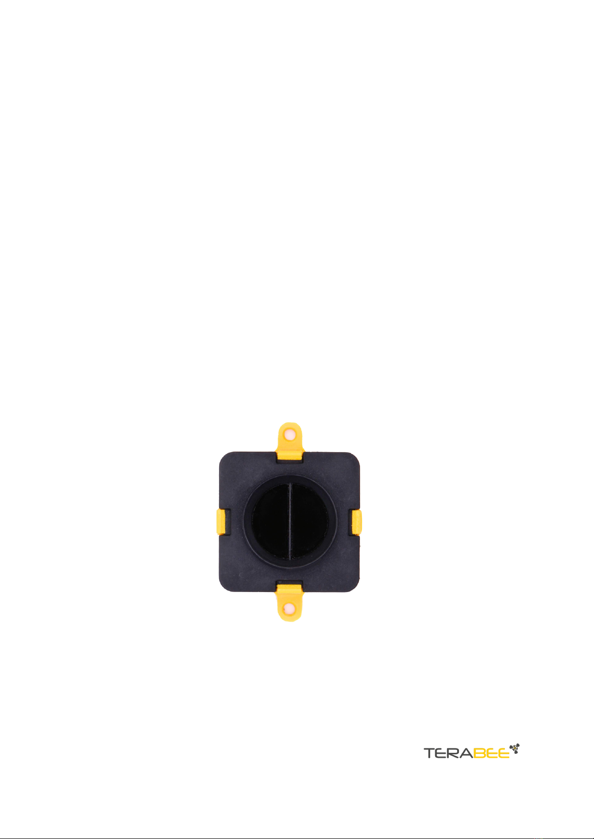
1.1. About the TeraRanger Evo People Counter 3
1.2. Technical specifications 4
1.2.1. Performance table 5
1.2.2. Communication interfaces 5
2. Mechanical integration 6
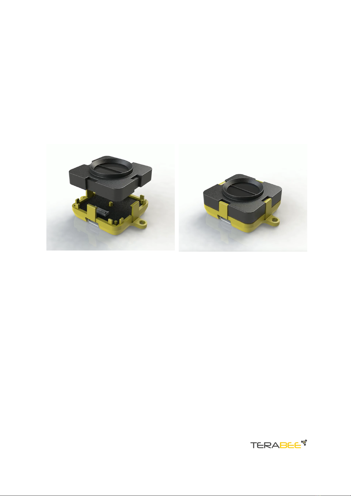
2.1. Modular design (clip-on, clip-off) 6
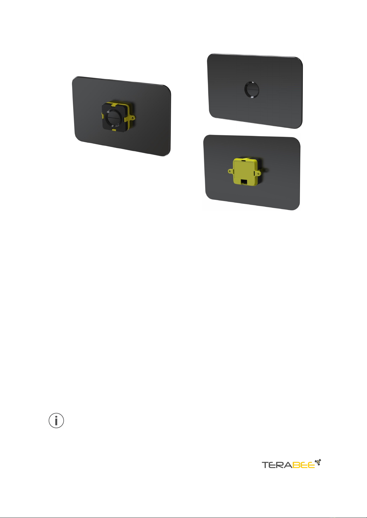
2.2. Mechanical design and mounting 6
2.3. Mounting solutions 8
3. USB Backboard Use 9
3.1. LED Indication 9
3.1.1. Normal operation 9
3.1.2. Error messages and troubleshooting 9
3.2. Connecting the TeraRanger Evo People Counter to a Host Computer 10
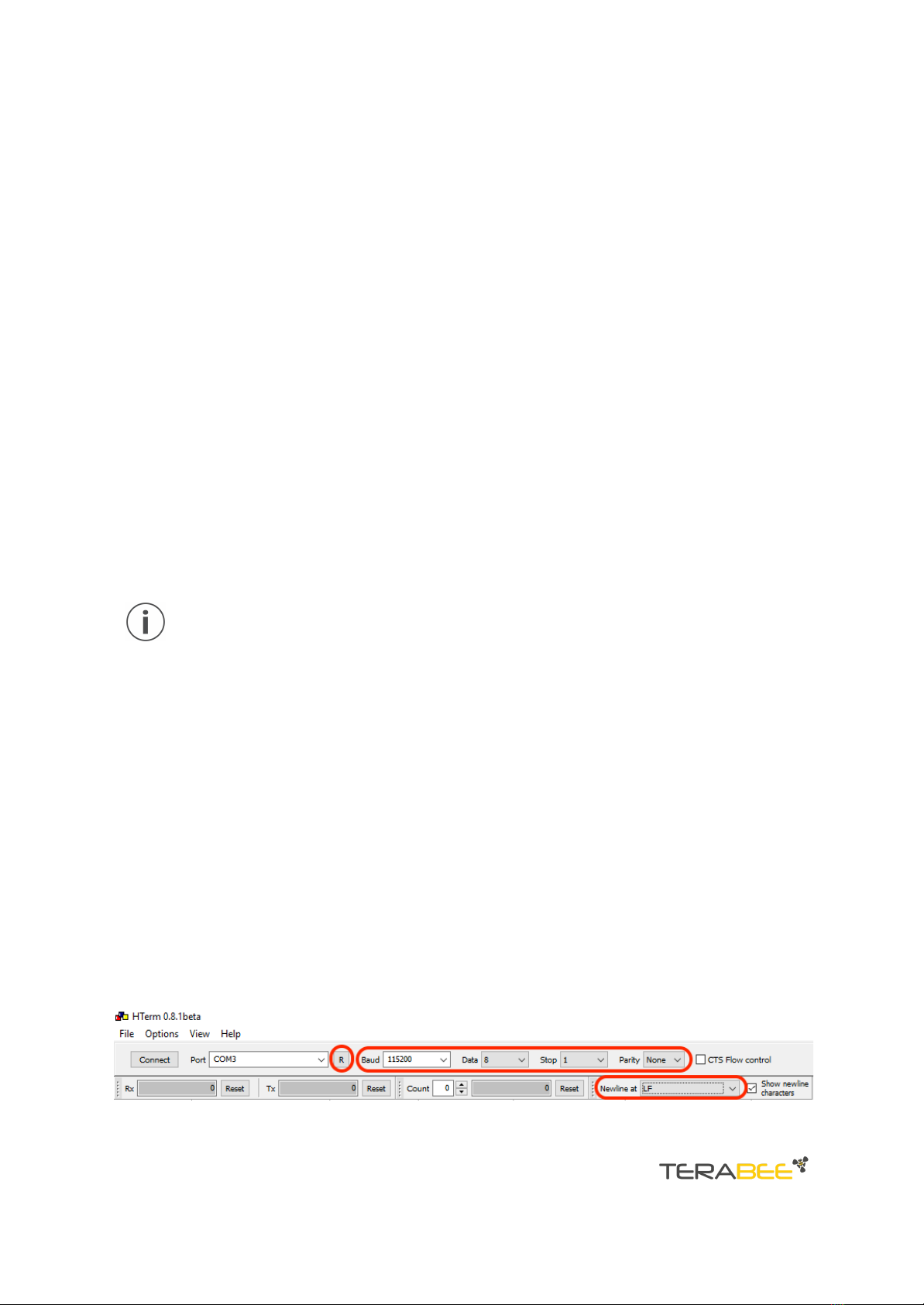
3.2.1. Windows OS 10
4. I2C/UART Backboard Use 13
4.1. I2C/UART pinout 13
4.2. LED Indicators 14
4.2.1. Normal operation 14
4.2.2. Troubleshooting 14
4.3. Electrical characteristics 14
5. USB/UART Normal Operation 16
5.1. Operation of the TeraRanger Evo People Counter sensor module 16
5.2. Installation of Graphical User Interface Package 16
5.2.1. Linux and Raspberry Pi 16
5.2.2. Windows 17
5.3. Graphical User Interface (GUI) 17
5.3.1. Bidirectional Traffic People Counting 18
5.3.2. Button to reset counters 18
5.4. List of sensor commands available via USB/UART 18
5.5. Details of the sensor output values 19
5.5.1. Reset counters 20
5.5.2. Parameters command 20
6. General remarks 21
Copyright © Terabee 2023
Terabee, 90 rue Henri Fabre
01630 Saint-Genis-Pouilly, France (next to CERN)
TeraRanger Evo People Counter
User Manual
2/21

1. Introduction
Small and discreet, the TeraRanger Evo People Counter measures pedestrian activity
and it has numerous applications across a range of sectors including retail, hospitality
and events, to name but a few.
This sensor module offers vertical and horizontal mounting options, and with a 0.05 m
to 1.5 m detection range, it delivers an optimal solution for measuring people flow in
corridors and allows door frame entrances integration.
Not only does the sensor register the number of people who have passed by, but
importantly, also their direction of travel. This extra insight into direction of flow
extends the applications beyond people counting measures, as it also allows an
understanding of how people flow within and around a space.
Because the Evo People Counter is based on Time-of-Flight technology, personal privacy
is protected and its technology is GDPR compliant by design.
1.1. About the TeraRanger Evo People Counter
Figure 1. TeraRanger Evo People Counter sensor, top view
The Evo People Counter sensor has no open electronics and provides an ABS protected
enclosure, resulting in a dust-proof and robust operation.
Copyright © Terabee 2023
Terabee, 90 rue Henri Fabre
01630 Saint-Genis-Pouilly, France (next to CERN)
TeraRanger Evo People Counter
User Manual
3/21

1.2. Technical specifications
Product code
TR-EVO-PPC-USB
TR-EVO-PPC-UART
Performance
Detection principle
Infrared Time-of-Flight
Light source wavelength
940 nm
Use environment
Indoor
Field of View
27°
Electronics
Supply voltage
5V DC +/-5%
Current consumption average
50 mA
Initialization time
< 1 s
Communication
Serial interface
USB 2.0 Micro-B
UART, +3.3V level, 115200,8,1, None
Visual notification
3 x LEDs (built-in backboards)
Mechanical data
Dimensions
42 x 30 x 13 mm (incl. backboard)
Weight
9 g (incl. backboard)
Operating temperature
-20° C to 75° C
Housing material
ABS
Mounting style
2 holes for M2 screws
Type of connection
USB Backboard: USB 2.0 Micro-B
I2C/UART Backboard: DF13-7p connector
Conformity
Reference standard
CE, RoHS
Table 1 - Technical specifications of TeraRanger Evo People Counter
Copyright © Terabee 2023
Terabee, 90 rue Henri Fabre
01630 Saint-Genis-Pouilly, France (next to CERN)
TeraRanger Evo People Counter
User Manual
4/21

1.2.1. Performance table
Mode
Detection
Output
Horizontal mounting
Vertical mounting
~ 0.05 m to 1.5 m
~ 2.0 m to 2.5 m
~25 Hz
Sensor ID
X: People inside (In - Out)
Y: People IN,
Z: People OUT
Table 2 - Performance table of the Evo People Counter
1.2.2. Communication interfaces
Evo People
Counter
Communication
Interfaces
USB
●
UART
●
Table 3 - Communication interfaces for the Evo People Counter
Copyright © Terabee 2023
Terabee, 90 rue Henri Fabre
01630 Saint-Genis-Pouilly, France (next to CERN)
TeraRanger Evo People Counter
User Manual
5/21

2. Mechanical integration
2.1. Modular design (clip-on, clip-off)
The mechanical design of the main sensor module (black) allows easy assembly to its
backboard (yellow) using a simple ‘clip-on’ technique. When clipping the two together,
please ensure there is no visible gap between the black and yellow parts.
Figure 2 - Modular design of the TeraRanger Evo People Counter sensor
2.2. Mechanical design and mounting
The TeraRanger Evo People Counter sensor offers an ABS housing (both: sensor and
backboard), with an option to mount the sensor using two holes compatible with M2
screws. Figure 3 illustrates the external dimensions of the TeraRanger Evo People
Counter sensor.
Copyright © Terabee 2023
Terabee, 90 rue Henri Fabre
01630 Saint-Genis-Pouilly, France (next to CERN)
TeraRanger Evo People Counter
User Manual
6/21

Figure 3 - TeraRanger Evo People Counter external dimensions, USB backboard
The USB Backboard includes two holes for mounting the sensor using standard M2
screws. The following methods can be used to mount the TeraRanger Evo People
Counter sensor:
1. Front-panel mount using the M2 screws
2. Back-panel mount using the 2mm ledge on the front side of the sensor
Figure 4 illustrates the two different mount methods. The first solution (1) allows for
easy surface attachment and rapid evaluation of the sensor. The second solution (2)
provides a more discreet installation and supports design-in projects by installing the
sensor behind a surface (e.g panel), ideally with 2mm thickness.
Copyright © Terabee 2023
Terabee, 90 rue Henri Fabre
01630 Saint-Genis-Pouilly, France (next to CERN)
TeraRanger Evo People Counter
User Manual
7/21

Figure 4 - Front-panel mounting (left image); back-panel mounting (right images)
2.3. Mounting solutions
When choosing a place for mounting the TeraRanger Evo People Counter, please
consider the following recommendations:
●Mounting close to sources of heat or strong electromagnetic fields can decrease
sensor performance
●Do not mount anything directly in front of the sensor or in a cone of
approximately +/-35° around the central optical axis of the sensor
●It is advisable to avoid having other sources of Continuous Wave or modulated
Infrared light sources near the sensor
●Please consider that dust, dirt and condensation can affect sensor performance
●It is not advised to add an additional cover in front of the sensor without any
custom calibration (contact Terabee)
●For an optimal placement of the People Counting sensor, please follow this
Application note
During assembly and integration, please observe all common ESD precautions. All
optical surfaces (sensor front) should be kept clean and free from contact with
chemicals.
Copyright © Terabee 2023
Terabee, 90 rue Henri Fabre
01630 Saint-Genis-Pouilly, France (next to CERN)
TeraRanger Evo People Counter
User Manual
8/21

3. USB Backboard Use
3.1. LED Indication
3.1.1. Normal operation
Three LED indicators are present on the USB backboard, and are visible through the
back of the yellow plastic case.
LED designator
Description
PWR (ORANGE)
The Power LED is ON whenever the sensor is powered
RED
Flashes briefly on startup to indicate proper initialization;
then switches off
GREEN
Blinks 8 times at power up
GREEN LED blinks every 5 seconds when the sensor is streaming
data
Table 4 - LED indicators of the USB backboard
3.1.2. Error messages and troubleshooting
LED
designator
Sequence
Signification
Corrective actions
RED
Continuous
blinking
Sensor has detected a fault
and has stopped functioning
Check that the sensor is
properly connected to the
backboard, then restart
the sensor
RED /
GREEN
Both LEDs
blinking
continuously
Sensor has detected a fault in
sensor initialization process
Check USB output for
details of the error
Verify that the sensor is
properly connected and
re-power the unit
Table 5 - USB backboard LEDs troubleshooting
Copyright © Terabee 2023
Terabee, 90 rue Henri Fabre
01630 Saint-Genis-Pouilly, France (next to CERN)
TeraRanger Evo People Counter
User Manual
9/21

3.2. Connecting the TeraRanger Evo People Counter to a
Host Computer
3.2.1. Windows OS
In Windows it is possible to use any terminal emulation software for data display.
Terabee works with and suggests using HTerm software. Please follow the provided link
to download the software file (http://www.der-hammer.info/terminal/), and select the
appropriate file for your platform.
Tested with version 0.8.4 on Linux x64 and Windows 10 x64 platforms.
When using Windows, extract the downloaded zip file to the selected folder,
openitanddouble click on the “HTerm.exe” file.
When using Linux, extract the downloaded tgz file to the selected folder. Make sure that
you have execution permission for the file “hterm” (command: chmod u+x hterm),
double click on the “hterm” file or run it from terminal while in its directory: ./hterm.
On Linux, consider removing the modemmanager package if you are sure that it is
not required by your system setup. This will shorten the initialization time of serial
devices in the Linux system:
sudo apt purge modemmanager
Connect the TeraRanger Evo People Counter to a computer and select the
corresponding USB port (click “R” button to refresh the port list). Please configure the
software with the following parameters:
Baud rate : 115200 bit/s
Data bits : 8
Stop bit : 1
Parity bit : None
For easier data reading, select the “LF” option from the “Newline at” drop-down field.
See Figure 5 below for visual instructions.
Copyright © Terabee 2023
Terabee, 90 rue Henri Fabre
01630 Saint-Genis-Pouilly, France (next to CERN)
TeraRanger Evo People Counter
User Manual
10/21

Click on LF, and in the line-end marker select the header of the operating mode for
easier data reading.
Figure 5 - HTerm parameters for TeraRanger Evo People Counter
Once the USB port is selected and the parameters correctly set, click on the “Connect”
button.
The TeraRanger Evo People Counter data will now appear in the “Received data” box
depending on the current working mode (see Figure 6).
Copyright © Terabee 2023
Terabee, 90 rue Henri Fabre
01630 Saint-Genis-Pouilly, France (next to CERN)
TeraRanger Evo People Counter
User Manual
11/21

Figure 6 - Example of Data stream on HTerm software
Copyright © Terabee 2023
Terabee, 90 rue Henri Fabre
01630 Saint-Genis-Pouilly, France (next to CERN)
TeraRanger Evo People Counter
User Manual
12/21

4. I2C/UART Backboard Use
The TeraRanger Evo People Counter sensor can output data through a UART interface
using an I2C/UART backboard.
Figure 8 - I2C/UART backboard front view
4.1. I2C/UART pinout
The I2C/UART backboard uses a single 9 pin Hirose DF13 connector for interfacing to
the host system. The mating connector is a Hirose DF13-9S-1.25C with crimping contacts
DF13-2630SCF (tin) or DF13-2630SCFA (gold). Please consider the mechanical stability of
the mated connectors and avoid any kind of excess force on the connector (during
installation and once integrated). Follow the recommendations in the Hirose DF13 series
datasheet (available here:
https://www.hirose.com/product/en/products/DF13) to ensure a reliable connection.
Pin
Designator
Description
1
Tx
UART transmit output. 3.3V logic
2
Rx
UART receive input. 3.3V logic
3
GND
Power supply and interface ground
4
SDA
I2C serial data line. 3.3V logic
5
SCL
I2C serial clock line. 3.3V logic
6
rfu
RESERVED FOR FUTURE USE
7
5V
+5V supply input
8
GND
Power supply and interface ground
9
rfu
RESERVED FOR FUTURE USE
Table 6 - Pinout and description (According to DF13 datasheet)
Copyright © Terabee 2023
Terabee, 90 rue Henri Fabre
01630 Saint-Genis-Pouilly, France (next to CERN)
TeraRanger Evo People Counter
User Manual
13/21

4.2. LED Indicators
4.2.1. Normal operation
The I2C/UART Backboard has three built-in LEDs behind the yellow case to visualize
feedback of the sensor status. Table 7 lists the functionality of each LED of the I2C/UART
backboard.
LED
Description
PWR (orange)
Power indicator, constantly ON when 5V is supplied
Rx (red)
Tx (green)
I2C/UART receive and transmit indicators.
Single blink for each data received or sent
Table 7 - LED indicators of the I2C/UART backboard
4.2.2. Troubleshooting
LED
designator
Sequence
Signification
Corrective actions
RED
Continuous
blinking
Sensor has detected a fault
and has stopped functioning
Check that the sensor is
properly connected to
the backboard, then
restart the sensor
RED /
GREEN
Both LEDs
blinking
continuously
Sensor has detected a fault
with the sensor initialization
process
Check I2C/UART output
for details of the error
Verify that the sensor is
properly connected and
restart
Table 8 - I2C/UART backboard LEDs troubleshooting
4.3. Electrical characteristics
Parameter
Minimum
Maximum
Average
Power supply
Voltage input (V)
Current consumption (mA)
4.5V
25mA
5.5V
75mA
5V
50mA
Copyright © Terabee 2023
Terabee, 90 rue Henri Fabre
01630 Saint-Genis-Pouilly, France (next to CERN)
TeraRanger Evo People Counter
User Manual
14/21

Interface logic levels
(referenced to +3V3)
LOW
HIGH
-
2.3
1
-
-
-
Table 9 - TeraRanger Evo People Counter power consumption
Copyright © Terabee 2023
Terabee, 90 rue Henri Fabre
01630 Saint-Genis-Pouilly, France (next to CERN)
TeraRanger Evo People Counter
User Manual
15/21

5. USB/UART Normal Operation
5.1. Operation of the TeraRanger Evo People Counter
sensor module
The TeraRanger Evo People Counter counts people passing by.
The output of the sensor is:
●A sensor ID, to allow the identification of the sensor when part of a multi-sensor
installation
●A meter counting the difference between In and Out
●A meter counting the number of people passing by, from left to right (In)
●A meter counting the number of people passing by, from right to left (Out)
The sensor should be installed with the USB/UART Connector placed on the right side,
as shown in Figure 9.
Figure 9: Sensor orientation for the Evo People Counter
The detection range of this mode can be adjusted from a minimum of 0.05 m to a
maximum of 1.7 m. To detect a person passing the set detection range has to be
breached.
5.2. Installation of Graphical User Interface Package
5.2.1. Linux and Raspberry Pi
Instructions:
●Open a terminal in the evo_people_counter folder
●Type: Pip install -r requirements.txt
●Launch: main.py by typing: python3 main.py
Copyright © Terabee 2023
Terabee, 90 rue Henri Fabre
01630 Saint-Genis-Pouilly, France (next to CERN)
TeraRanger Evo People Counter
User Manual
16/21

5.2.2. Windows
Instructions:
●Double click on EvoPeopleCounter_1.0 to launch executable and Install
●To launch the GUI double click on the icon “EvoPeopleCounter” on the Desktop
●To launch with terminal information, right click on the icon and choose “Open file
location”
●Open a cmd terminal there and type the command: “cd ..” and then
Python\python.exe pkgs\main.py
5.3. Graphical User Interface (GUI)
The GUI allows you to:
●Set up the maximum and minimum range threshold of the people counting
●Test in near real-time the behavior of Evo People Counter sensor and report the
status and counts related to its different modes
Important:
Once you update the parameters through the GUI (e.g. Presence Detection Mode
or thresholds with the sliders), these parameters are automatically pushed to
the TeraRanger Evo People Counter sensor
You can read the details of the GUI on Figure 11 below.
The GUI uses the concept of classic people counting and will show the number of
people that have entered a room or zone and the number of people that have left the
zone or room. A simple subtraction is made to display the number of people calculated
to be inside the room or zone, in real-time.
The sensor, however, has 3 outputs, including the calculated number of people inside,
the number of people counted in or the number of people counted out. Whilst we use
the term “In” and “Out” this could be substituted with the words left and right, signifying
people passing the sensor in one direction or another. In this way you can use the
sensor for classic people counting applications, but also for the simple measurement of
footfall in a corridor or other defined area.
Copyright © Terabee 2023
Terabee, 90 rue Henri Fabre
01630 Saint-Genis-Pouilly, France (next to CERN)
TeraRanger Evo People Counter
User Manual
17/21

Figure 11: GUI in standard mode
5.3.1. Bidirectional Traffic People Counting
The three numbers below the title correspond to three meters:
●Meter 1 displays the difference between the 2nd and the 3rd meter (People Inside:
In - Out)
●Meter 2 counts people passing by from left to right (In),
●Meter 3 counts people passing by from right to left (Out)
5.3.2. Button to reset counters
●Reset Bidirectional Counter: reset the counts to: 0 0 0
5.4. List of sensor commands available via USB/UART
The commands listed below can be used to push default parameters to an Evo People
Counter sensor via a command line within an HTerm window, or through a Python
script for example.
Copyright © Terabee 2023
Terabee, 90 rue Henri Fabre
01630 Saint-Genis-Pouilly, France (next to CERN)
TeraRanger Evo People Counter
User Manual
18/21

Command (HEX)
CRC-8
Command description
00 55 03 MM NN SS TT
Dependent
on the
value of:
MM,NN,
SS,TT 1
CHANGE BPTD THRESHOLDS SETTING:
MMNN <= 1700 (millimeters)
50 <= SSTT (millimeters)
(SSTT + 200) <= MMNN (millimeters)
00 55 08 00 00 00 00
7C
RESET BIDIRECTIONAL PEOPLE TRAFFIC COUNTING
00 61 01
E7
OUTPUT SETTING:
BINARY OUTPUT PARAMETERS SETTINGS VALUES
00 61 02
EE
OUTPUT SETTING:
TEXT OUTPUT PARAMETERS SETTINGS VALUES
1 Where MM NN SS TT is max and min of BPTD thresholds in hexadecimal format. (order is very important)
Table 10 - List of commands for TeraRanger Evo People Counter
Please refer to Connecting the TeraRanger Evo to a Host Computer for instructions on
how to send commands to the TeraRanger Evo People Counter sensor using a host
computer and the HTerm emulation software.
Each command message frame must be transmitted in a continuous stream, ie.
not byte by byte
It is advised to maintain a time interval of a few microseconds between two
messages for proper command registration
5.5. Details of the sensor output values
When streaming data using HTerm, the TeraRanger Evo People Counter sensor goes on
streaming frames that contain a header of “DD” followed by two distances. Each
distance is represented by two bytes and one CRC byte.
“DD”
Distance 1 (2 bytes)
Distance 2 (2 bytes)
CRC-8 (1 byte)
Once the sensor detects and validates the Bidirectional Traffic People Counting, the
sensor outputs the following frame that contains this additional information:
“PC”
Sensor_id
(4 bytes)
People counter
(4 bytes)
Count IN
(2 bytes)
Count OUT
(2 bytes)
CRC-8 (1
byte)
Copyright © Terabee 2023
Terabee, 90 rue Henri Fabre
01630 Saint-Genis-Pouilly, France (next to CERN)
TeraRanger Evo People Counter
User Manual
19/21

Where: “PC”: frame header.
Sensor_ID
Counter = Counter IN - Counter OUT
Counter IN: number of people passing by from Left to Right
Counter OUT: number of people passing by from Right to Left
CRC_8 Byte
5.5.1. Reset counters
RESET COUNTERS : 00 55 08 00 00 00 00 7C
This command will reset the counters for both presence detection and bidirectional
people traffic detection modes.
5.5.2. Parameters command
PARAMETERS FRAMES (BINARY) : 00 61 01 E7
This command provides users with all parameter values in binary form and returns the
following frames:
“BP”
Maximum_Thresholds (2 bytes)
Minimum_Thresholds (2 bytes)
Copyright © Terabee 2023
Terabee, 90 rue Henri Fabre
01630 Saint-Genis-Pouilly, France (next to CERN)
TeraRanger Evo People Counter
User Manual
20/21
This manual suits for next models
1
Table of contents
Other TeraBee Cash Counter manuals