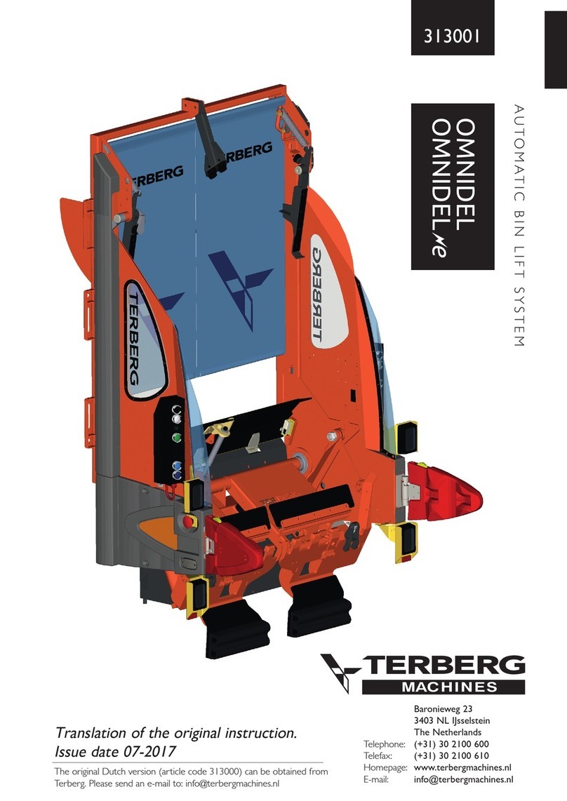
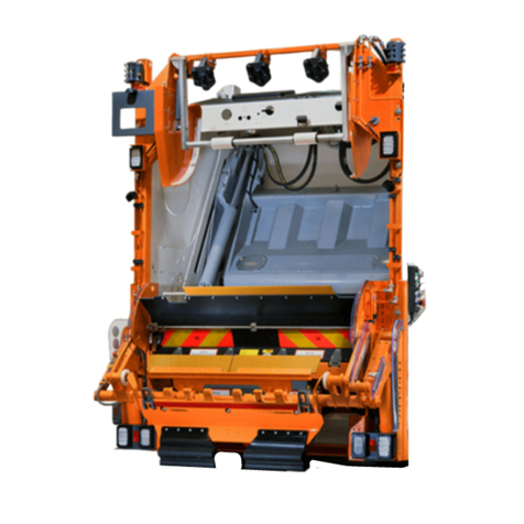
Terberg OmniMAX User manual

A U T O M AT I C B I N L I F T S Y S T E M
37679
Baronieweg 23, 3403 NL, IJsselstein
The Netherlands
Telephone: (+31) 30 2100 600
Telefax: (+31) 30 2100 610
Homepage: www.terbergmachines.nl
E-mail: info@terbergmachines.nl
Translation of the original instruction.
Issue date 05-2017
The original utch version (article code 37658) can be obtained
from Terberg.
Please send a mail to: inf[email protected]
OMNIMAX

2EN
EN
Contents
37679
05-2017
ãTerberg Machines B.V., IJsselstein, The Netherlands
All rights reserved. No part of this book may be reproduced, stored in database or retrieval system, or published, in any form or in any
way, electronically, mechanically, by print, photoprint, microfilm or any other means without prior written permission from the publisher.
Page Page
FOREWORD
•General 3
•Warranty 3
•Requirements laid down for the operative 3
•Symbols used 3
•Description of sections 3
•Type indication 3
1. INTRODUCTION
1.1 Description of the bin lift system 4
1.2 Technical specifications 5
Bin and bin lift information 5
2. SAFETY
2.1 General safety instructions 6
2.2 Safety instructions
uring use of the bin lift system 7
uring maintenance and repair 7
2.3 Warning signs 8
2.4 Safety equipment: Emergency stop button
General 9
Operation of emergency stop button 9
2.5 Safety equipment: RPD
Operation of underwalk protection (RP ) 10
3. BIN LIFT OPERATION
3.1 Important components 12
3.2 Warnings and tips 13
3.3 Daily checks 13
3.4 Loading bags and/or bulky waste 14
3.5 Manual emptying of 40 litre bins 14
3.6 Manual emptying of 2-wheel bins 15
3.7 Automatic emptying of 2-wheel bins 16
3.8 Manual emptying of 4-wheel flat-topped 18
bins, capacity 500 to 1280 litres
3.9 Manual emptying of 4-wheel roll-topped 19
bins, capacity 770 and 1100 litres
3.10 Loading 4-wheel Bammens bins 20
with Bammens pick-up arms (option)
3.11 Loading 4-wheel roll-topped bins 21
with DIN pick-up arms (option)
3.12 Loading 4-wheel flat-topped bins 22
with DIN pick-up arms (option)
3.13 One-man operation / automatic 23
handling of 4-wheel bins (option)
3.14 Emptying 4-wheel bins with the 24
semi-automatic function (option)
3.15 Travel height and footboards 25
4. DIAGNOSTIC SYSTEM
•Introduction: the 4 levels 26
•Working with the configuration program 26
•Level 1 26
•Level 2 27
•Level 3 and 4 28
•Level 4 (continued) 29
5. MAINTENANCE AND CLEANING
5.1 General and daily maintenance 30
5.2 Weekly maintenance 30
5.3 6-Weekly maintenance 31
5.4 Annual maintenance 31
5.5 Adjustment of the ultrasonic sensors 32
5.6 Maintenance schedule 33
6. DECOMMISSIONING (disposing) 32
7. DIMENSIONS
Bin lift system 34
8. ELECTRICAL COMPONENTS
Cable harness A 36/37
Cable harness B 38/39
Cable harness C 40
Cable harness V (37637) 41
Cable harness V (37643) 42
List of inputs and outputs 43
List of alarm texts 44
9. YDRAULIC CONNECTIONS AND
COMPONENTS 45
ydraulic block, overview components 46
ydraulic connections bin lift system 47
10. PNEUMATIC CONNECTION
Bin stop / catcher bar 48
11. TROUBLES OOTING 49
PARTS BOOK 101

EN 3
EN
37679
05-2017
Foreword
ãTerberg Machines B.V., IJsselstein, The Netherlands
All rights reserved. No part of this book may be reproduced, stored in database or retrieval system, or published, in any form or in any
way, electronically, mechanically, by print, photoprint, microfilm or any other means without prior written permission from the publisher.
Foreword
This user manual gives a quantity of information on
the operation and maintenance of the OmniMAX
bin lift system.
In order to work safely and efficiently with this auto-
matic bin lift you need to read this manual through
carefully before you start using the bin lift.
Make the user manual available to all persons invol-
ved in the operation and/or the maintenance of the
bin lift.
When necessary also consult the user manual of the
refuse collection vehicle and the refuse body.
When all the operating and maintenance instructions
have been met the bin lift can be safely used.
Should you nonetheless have any further questions,
contact your distributor.
Warranty
If you would like more information about the war-
ranty terms and conditions, contact your distributor.
Requirements laid down for the operative
- The bin lift may only be operated by persons who
are familiar with the operation of the bin lift.
- Repairs may only be carried out by qualified
personnel.
Symbols used
Note:
Additional information.
Warning:
If these instructions are not followed, there
is a risk of damage to the equipment
and/or personal injury.
Stop:
If these instructions are not followed cor-
rectly, there is a risk of personal injury
and/or risk of serious damage to the equip-
ment.
The user manual contains the following sec-
tions:
Introduction
A description of the intended use, conditions of use
and operating principle of the machine.
Safety
escription of the safety equipment and the meas-
ures that must be taken into account to work safely
with the machine, together with an explanation of
the symbols present on the machine.
Operation
A clear description of the main components and
instructions for emptying different types of bins.
Maintenance and cleaning
Includes all the regular operations necessary for the
proper functioning of the machine.
Technical info
Electrical connections and controls, hydraulic con-
nections and components, troubleshooting and
parts.
Type indication
Each bin lift is provided with a type plate with the
type indication, machine number and year of con-
struction. The type plate can be found on the right-
hand side of the frame.

1
9
11
10
12
7
3
14
4
13
5
6
13
65
4
12
7
8
2
3
14
Persruimte
4EN
EN
1. Introduction
37679
05-2017
1.1
Description of the bin lift system
1 = Control panel A (left)
2 = Control panel B (right)
3 = Safety arm with sensor
4 = Pick-up comb
5 = Bin security switch
6 = Start sensor
7 = Emergency stop button
8 = iagnostic box
9 = Hopper plate
10 = Bin stop / catcher bar (2 positions)
11 = ust curtain
12 = Warning edge
The OmniMAX is an automatic bin lift system that
can be used very widely. It is not only suitable for
emptying commonly used 2-wheel bins but also for
most 4-wheel bins.
With the (optional) pick-up arms, refuse bins that
are not suitable for comb pick-up can still be emp-
tied.
Thanks to the low opening height the bin lift is also
very suitable for collecting “loose” dirt.
ãTerberg Machines B.V., IJsselstein, The Netherlands
All rights reserved. No part of this book may be reproduced, stored in database or retrieval system, or published, in any form or in any
way, electronically, mechanically, by print, photoprint, microfilm or any other means without prior written permission from the publisher.
A7
A6
A5
A3
A4
A2
A1
A8
A14
A13
A11
A12
A10
A9
A
B8
B14
B13
B11
B12
B10
B9
B7
B6
B5
B3
B4
B2
B1
B
VERVALLEN LAY-OUT
maar in gebruik voor
de losse knop plaatjes.
A7
A6
A5
A3
A4
A2
A1
A8
A14
A13
A11
A12
A10
A9
A
B8
B14
B13
B11
B12
B10
B9
B7
B6
B5
B3
B4
B2
B1
B
VERVALLEN LAY-OUT
maar in gebruik voor
de losse knop plaatjes.
12
Optional: 13 = Bammens/Geesink or
Bammens/Kronenburg
pick-up arms
14 = IN pick-up arms
Compaction area

2-wheel
bins
4-wheel
flat-topped bins
4-wheel
roll-topped bins
4-wheel Bammens
pick-up bins
Capacity (litres) 80* - 360 500 - 770
1000 - 1280 770 - 1100 500 tot 1700
According to standard EN 840-1 EN 840-2 EN 840-3 EN 840-4
Lifting capacity 1500 N (150 kg) 7500 N (750 kg)
Cycle time ±7 seconds ±12 seconds
Emptying time Adjustable
Automatic emptying yes no no no
Manual emptying yes yes yes yes
Pick-up via comb yes yes yes no
Bammens pick-up arms not applicable not applicable not applicable (option)
DIN pick-up arms not applicable (option) (option) not applicable
Catcher bar not applicable not applicable yes not applicable
Bin stop Forward position
Forward position
(500-770)
Rearward position
(1000-1280)
Forward position Rearward position
EN 5
EN
37679
05-2017
1. Introduction
1.2
Technical specifications
ãTerberg Machines B.V., IJsselstein, The Netherlands
All rights reserved. No part of this book may be reproduced, stored in database or retrieval system, or published, in any form or in any
way, electronically, mechanically, by print, photoprint, microfilm or any other means without prior written permission from the publisher.
Bin and bin lift information
Directives and Standards 2006/42/EG, EN 1501-1 & EN 1501-5: 2011
Weight 678 kg
Sound pressure 65 dB(A)
Vibration 2,5 m/s2
Operating voltage 24 Volts
Current 10 Ampère
Oil flow 40-60 litre/minute
Operating pressure PTO Min. 180 bar / Max. 250 bar
40 litre bins (option)
As an option 40 litre bins, with a body height of 44 cm, can be emptied with this bin lift.
However, since there are also 40 litre versions on the market with a body height of 46 cm, these may come wit-
hin the range of the start sensor and activate the automatic function and that is undesirable.
The automatic emptying of this 46 cm high 40 litre version, and other bins without wheels, is however
absolutely not permitted.
* Only 80 litre bins with a minimum rim height of 86 cm (according to EN 840-1) can be emptied with this bin lift.
The emptying of in types other than those
indicated a ove, is not permitted with this in
lift system.

•Technical faults must be reported immediately to
the person responsible for supervising the bin lift.
The bin lift must be taken out of service until the
fault has been rectified (if this may be dangerous).
•Never use the lifting chair or other parts of the
bin lift system as a seat,
this is extremely dange-
rous!
•Under no circumstances may the controls be
changed.
•Under no circumstances may any of the safety
provisions fitted be removed or changed.
•on’t blind off or cover the ultrasonic sensors, fit-
ted in the safety arms, under any circumstances.
•If the safety provisions are damaged they must be
repaired or replaced immediately by original parts.
•Under no circumstances may the cycle speeds and
lifting forces set by the manufacturer be changed.
•Operating and safety decals must be present and
properly legible.
•Actions that override the safety provisions are
expressly forbidden!
•Reversing is only permitted when the lifting chairs
are at a safe height.
•It is prohibited to stand on the footboards while
the refuse collection vehicle is reversing.
•Make sure that you are visible to the driver of the
refuse collection vehicle while it is reversing.
•Check the lights in the controls daily, faulty lights
must be replaced as soon as possible.
•The bin lift may never be used as a hoisting instru-
ment.
•Vehicles must not be towed by attaching the
towing cable to the bin lift.
•The refuse collection vehicle may never be lifted
by the lifting points of the bin lift.
•The lifting chairs must be at transport height while
driving.
•When riding on the vehicle you must absolutely
not sit or stand on parts of the machine other
than the special footboards for this purpose,
this
really is extremely dangerous!
•It is not wise to work with the bin lift in extreme-
ly bad weather conditions (storm, thunderstorm,
etc.).
6EN
EN
2. Safety
37679
05-2017
2.1
General safety instructions
ãTerberg Machines B.V., IJsselstein, The Netherlands
All rights reserved. No part of this book may be reproduced, stored in database or retrieval system, or published, in any form or in any
way, electronically, mechanically, by print, photoprint, microfilm or any other means without prior written permission from the publisher.
Terms of conformity
This bin lift conforms to the current standards at the
time of production. It has been tested and checked,
on a rig, in normal conditions with an increase of
25% weight in static and 10% weight in dynamic
operation.
It is the end user’s responsibility to maintain the
equipment in accordance with the manufacturer’s
recommendations, also if there is a risk of damages
or injury the bin lift must be taken out of service
immediately.
General
•The bin lift may never be operated when the refu-
se collection vehicle is travelling along and also not
with reverse gear engaged.
•The bin lift may only be operated by persons who
are familiar with the operation of the bin lift.
•First read the operating instructions before you
start using the bin lift.
•Read through the operating instructions for the
compaction body carefully.
•In your daily work as bin lift operative you are
working in traffic, do not put it or yourself in dan-
ger.
•Before you start your round agree with your col-
leagues how to proceed in certain situations such
as stopping, driving off, etc.
•When you are working with the bin lift, you
should not wear any loose clothing and jewellery.
•When working always wear work clothing, safety
footwear and work gloves that comply with the
standards indicated in the table below.
•Make sure that an unattended bin lift can never be
put into operation by unauthorised persons
(remove the ignition key).
•o not start using the bin lift in areas or by instal-
lations where due to the presence of gases and/or
flammable substances there is a fire and/or explo-
sion hazard.
•The bin lift may not be used under any circum-
stances where there is an oil supply of more than
60 litres/minute.
Personal protection
equipment: According to standard:
Work clothing NEN-EN-ISO 20471:2013
Safety footwear NEN-EN-ISO 20345:2011
Work gloves NEN-EN 420:2003+A1:2009

EN 7
EN
37679
05-2017
2. Safety
2.2
Safety instructions during use, maintenance and repair
ãTerberg Machines B.V., IJsselstein, The Netherlands
All rights reserved. No part of this book may be reproduced, stored in database or retrieval system, or published, in any form or in any
way, electronically, mechanically, by print, photoprint, microfilm or any other means without prior written permission from the publisher.
During use of the bin lift system
•When the bin lift system is in operation, you
should not under any circumstances reach into the
lifting system (danger of injury!).
•In case of danger immediately press the closest
emergency stop switch (see section Safety equip-
ment).
•Check that there are no foreign objects in or
between the bin lift system that hinder the opera-
tion.
•It is not permitted to load loose dirt above the
hopper edge.
•Compaction may not be carried out when objects
are protruding out of the opening.
•o not use the bin lift system in conditions where
there is a restricted view of the bin lift.
•o not use the bin lift system on a very uneven
surface.
•The bin lift must not be driven against a bin or a
heap of refuse.
•Take into account the heating of the hydraulic oil,
the oil may be 40˚ Celsius hotter than the ambient
temperature. As a result the piping and hoses may
cause burns at high ambient temperatures.
•on’t go between the safety arms if the automatic
function is activated.
•Always switch the automatic function off if for any
reason you need to enter between the safety
arms.
•Make sure that there are no persons in the imme-
diate vicinity of the bin lift during the loading cycle.
•Working with bin types other than those indicated
in the manual is not permitted.
•Nothing may protrude out of the bin, only bins
whose top is completely closed may be emptied.
•o not empty any damaged bins, these may cause
problems.
•Excessively heavy bins must be removed from
the bin lift:
max. lifting capacity 2-wheel bin: 1500N (150kg)
max. lifting capacity 4-wheel bin: 7500N (750kg)
•Let go of the bin as soon as it is lifted by the bin
lift.
•Check that the bin is sitting correctly on the pick-
up comb before you empty it.
•Because the bin security switch is deactivated
during manual operation, you must keep a sharp
eye out that the bin is hanging properly on the
pick-up comb.
•It is expressly prohibited to help the bin lift system
‘manually’ with lifting.
•Only give an extra shake if this is needed.
•Only remove the bin when the bin lift has come to
a standstill and the bin is standing on the ground
again.
•Place empty bins where they do not cause danger
to other road users.
•It is prohibited to empty bins holding dangerous
and/or radioactive substances.
•It is prohibited to empty bins holding smouldering
or burning substances.
•Never walk backwards towards the bin lift system.
•One person offering and/or taking several bins at
the same time must be kept to a minimum.
•Check that the bin is sitting properly on the IN /
BAMMENS pick-up arms, before you empty it.
•A bin may only be offered when it is held by the
handle bars.
During maintenance and repair
•It is only permitted for authorised technical pers-
onnel to perform maintenance and carry out
repairs.
•Faults identified must be rectified before the bin
lift is taken into service.
•Switch off the bin lift during maintenance and
repairs (turn off the motor of the refuse collec-
tion vehicle and switch off the main power
switch).
•Inadvertent switching on must be made impossible
while working, remove the ignition key.
•You should not get under the lifting chairs during
repair or cleaning, unless these are supported.
•Before starting cleaning, you must switch off the
drive of the refuse collection vehicle.
•Grease may flow out between the pivot points if a
high pressure hose is used, think about your eyes,
always use safety goggles.
•Use the lifting points present for raising the bin lift.
•When working on the hydraulic system you must
take into account that this is filled with pressurised
hydraulic oil. Always use personal protection
equipment to avoid contact with the skin and eyes.
Use absorbents to avoid environmental pollution.
•You must comply with the maintenance interval
specified by the manufacturer.

Warning signs
All safety and instruction stickers affixed must be
replaced if damaged.
The pictogram stickers have the following meaning:
o not stand under the lifting chair!
o not stand behind a working bin lift!
o not reach into the bin lift, danger of
injury!
8EN
EN
2. Safety
37679
05-2017
2.2
Safety instructions
(continued)
ãTerberg Machines B.V., IJsselstein, The Netherlands
All rights reserved. No part of this book may be reproduced, stored in database or retrieval system, or published, in any form or in any
way, electronically, mechanically, by print, photoprint, microfilm or any other means without prior written permission from the publisher.
•Electrical fuses should never be bridged or replaced
by a fuse with a higher power rating.
•Upon dismantlement, disconnect the plugs and
connections from the vehicle.
•After a collision with the bin lift, Terberg must
assess whether the bin lift is still safe to use and
whether this must first be repaired.
•uring maintenance and repairs original or speci-
fied parts must always be used.
2.3
Warning signs

EN 9
EN
37679
05-2017
2. Safety
2.4
Safety equipment: Emergency stop button
ãTerberg Machines B.V., IJsselstein, The Netherlands
All rights reserved. No part of this book may be reproduced, stored in database or retrieval system, or published, in any form or in any
way, electronically, mechanically, by print, photoprint, microfilm or any other means without prior written permission from the publisher.
General
•If during collection the bin lift system does not
work or works insufficiently, the workshop or ser-
vice station should be notified immediately, with as
clear as possible a description of the complaint.
•Warning stickers and operating stickers that are
no longer clearly legible must be replaced.
Emergency stop button
In case of need, you can
stop the lifting cycle and the
compaction equipment
immediately with the emer-
gency stop buttons fitted to
both sides of the bin lift.
After pressing the emer-
gency stop button, the
hydraulic oil supply stops
and the electrical circuit is
interrupted.
•The control lights go out. The driver of the refuse
collection vehicle is warned by a buzzer sound in
the cab that the emergency stop button has been
pressed.
Resetting emergency stop button
Reset the emergency stop
button by pulling it out. The
buzzer in the cab stops.
Press the dark blue descent button (A14
and B14).
The lifting chair descends to the ottom posi-
tion.
•Eliminate the need for the intervention.
•Remove the bin from the lifting chair.
•
The bin lift system is ready for use again.
Entrapment
A dangerous situation occurs if someone is entrap-
ped and the hydraulic system is still pressurised.
When the bin lift is deactivated after pressing the
emergency stop button, it is not possible to lower
the lifting chairs without resetting the emergency
stop button.
In such cases proceed as follows:
Reset the emergency stop
button by pulling it out. The
buzzer in the cab stops.
Press the dark blue descent button (A14
and B14).
The lifting chair descends to the ottom posi-
tion.
A7
A6
A5
A3
A4
A2
A1
A8
A14
A13
A11
A12
A10
A9
A
B8
B14
B13
B11
B12
B10
B9
B7
B6
B5
B3
B4
B2
B1
B
VERVALLEN LAY-OUT
maar in gebruik voor
de losse knop plaatjes.
A7
A6
A5
A3
A4
A2
A1
A8
A14
A13
A11
A12
A10
A9
A
B8
B14
B13
B11
B12
B10
B9
B7
B6
B5
B3
B4
B2
B1
B
VERVALLEN LAY-OUT
maar in gebruik voor
de losse knop plaatjes.
Repairs may only e carried out y qualified
personnel, never rectify faults yourself, this
may cause danger for you and damage to the
in lift system!

Underwalk protection (Rear Protective Device)
To comply with European Standard EN 1501-5, all
automatic and semi-automatic bin lift systems are
equipped with RP .
This safety equipment protects persons approaching
the bin lift when it is emptying automatically (or semi-
automatically).
This safety equipment consists of two ultrasonic sen-
sors, fitted to the two safety arms. The sensors detect
persons or objects coming within the protected area
of the bin lift. This occurs separately for each lifting
chair.
The underwalk protection (RPD) is therefore only
active when lifting automatically (or semi-automa-
tically) and the safety arms are folded down.
BeveiligdgebiedBeveiligd gebied
10 EN
EN
2. Safety
37679
05-2017
ãTerberg Machines B.V., IJsselstein, The Netherlands
All rights reserved. No part of this book may be reproduced, stored in database or retrieval system, or published, in any form or in any
way, electronically, mechanically, by print, photoprint, microfilm or any other means without prior written permission from the publisher.
•As soon as the area under a lifted bin is entered,
during automatic or semi-automatic lifting, the
downward movement is stopped.
- A warning light mounted on top of each safety
arm comes on and indicates that the RP has
been activated on this side of the bin lift.
- Automatic (or semi-automatic) lifting does
however remain active, the green light flashes.
•Lower the chair manually using the manual push-
buttons, the warning light goes out and the RP is
reset.
- The bin lift is again ready to lift bins automatical-
ly (or semi-automatically), the green light shows
a steady light again.
The sensors are checked during each automatic lif-
ting operation. When a sensor fault is identified the
automatic lifting is switched off.
•The RP system is designed such that it is not acti-
vated by rain or snow.
When refuse, snow or another object block the
‘unobstructed view’ of a sensor, the lifting chair
will rise and then stop.
- The warning light on top of the arm will flash.
This flashing indicates that the “unobstructed
view” of the sensor is blocked, or that there is a
fault in the RP system.
- The bin lift still works manually, even with a fault
in the RP .
Because the RP sensors monitor both sides of the
bin lift separately, in case of a defect on one side the
other will still lift automatically.
Semi-automatic function 4-wheel bins (option)
When the bin lift is equipped with the semi-automa-
tic function 4-wheel bins, the activation of the RP
on one of the two sides will result in the bin lift stop-
ping in the tipping position.
2.5
Safety equipment: Underwalk protection
Protected areaProtected area
In case of damage to the safety equipment,
this must e repaired or replaced y original
parts immediately.
Repairs to the RPD may only e carried out y
qualified personnel.
Keep a minimum distance of 2.5 meter
etween the in lift and o jects which are
located ehind the in lift system. This is to
avoid dangerous situations in case that a in
falls from the pick-up com .

EN 11
EN
37679
05-2017
ãTerberg Machines B.V., IJsselstein, The Netherlands
All rights reserved. No part of this book may be reproduced, stored in database or retrieval system, or published, in any form or in any
way, electronically, mechanically, by print, photoprint, microfilm or any other means without prior written permission from the publisher.
T IS PAGE INTENTIONALLY LEFT BLANK

12 EN
EN
3. Bin lift operation
37679
05-2017
ãTerberg Machines B.V., IJsselstein, The Netherlands
All rights reserved. No part of this book may be reproduced, stored in database or retrieval system, or published, in any form or in any
way, electronically, mechanically, by print, photoprint, microfilm or any other means without prior written permission from the publisher.
1
9
11
10
12
7
3
14
4
13
5
6
13
65
4
12
7
8
2
3
14
Persruimte
3.1
Important components
1 = Control panel A (left)
2 = Control panel B (right)
3 = Safety arm with sensor
4 = Pick-up comb
5 = Bin security switch
6 = Start sensor
7 = Emergency stop button
8 = iagnostic box
9 = Hopper plate
10 = Bin stop / catcher bar (2 posi-
tions)
11 = ust curtain
12 = Warning edge
Optional
13 = Bammens / Geesink or
Bammens / Kronenburg
pick-up arms
14 = IN pick-up arms
A7
A6
A5
A3
A4
A2
A1
A8
A14
A13
A11
A12
A10
A9
A
B8
B14
B13
B11
B12
B10
B9
B7
B6
B5
B3
B4
B2
B1
B
VERVALLEN LAY-OUT
maar in gebruik voor
de losse knop plaatjes.
A7
A6
A5
A3
A4
A2
A1
A8
A14
A13
A11
A12
A10
A9
A
B8
B14
B13
B11
B12
B10
B9
B7
B6
B5
B3
B4
B2
B1
B
VERVALLEN LAY-OUT
maar in gebruik voor
de losse knop plaatjes.
2. Control panel RIG T
BIndicator light: Operation right active
B1 * Pushbutton:
Release function compactor
B2 (
option
)Selector button/indicator:
Automatic compaction cycle - 0x / 1x /
2x / 3x
B3 Selector button/indicator: Shake selec-
tion 2-wheel bins - 0x / 1x / 2x
B4 (
option
)Pushbutton: Travel height
B5 (
option
)Pushbutton: Semi-automatic
4-wheel bins
B6 Pushbutton: Hopper plate UP
B7 Pushbutton: Hopper plate OWN
B8 * Pushbutton: Compaction body manual
actuation / compaction 1x
B9 Pushbutton: Acoustic signal cab
B10 Pushbutton/indicator: Automatic
2-wheel bins in operation
B11 Pushbutton/indicator: Catcher bar to
FORWAR , then light comes on
B12 Pushbutton/indicator: For 4-wheel bins
the light must come on
B13 Pushbutton: Raise lifting chair right or
raise 4-wheel bins
B14 Pushbutton: Lower lifting chair right or
lower 4-wheel bins
1. Control panel LEFT
AIndicator light: Operation left active
A1 * Pushbutton:
Release function compactor
A2 (
option
)Selector button/indicator:
Automatic compaction cycle - 0x / 1x /
2x / 3x
A3 Selector button/indicator: Shake selec-
tion 2-wheel bins - 0x / 1x / 2x
A4 (
option
)Pushbutton: Travel height
A5 (
option
)Pushbutton: Semi-automatic
4-wheel bins
A6 (
option
)Pushbutton: Hopper plate UP
A7 (
option
) Pushbutton: Hopper plate
OWN
A8 * Pushbutton: Compaction body manual
actuation / compaction 1x
A9 Pushbutton: Acoustic signal cab
A10 Pushbutton/indicator: Automatic
2-wheel bins in operation
A11 (
option
)Pushbutton/indicator: Catcher
bar to FORWAR , then light comes on
A12 (
option
)Pushbutton/indicator: For
4-wheel bins the light must come on
A13 Pushbutton: Raise lifting chair left or
raise 4-wheel bins
A14 Pushbutton: Lower lifting chair left or
lower 4-wheel bins
Function transfer between control panels
If a 4-wheel bin is moved via a control panel, it is not
possible to transfer the control to the other side. This
can only be done when the bin is back on the ground
and is removed.
Automatic compaction cycle
Use the optional automatic com-
paction cycle function (button
A2 or B2) with care, this avoids
unnecessary wear and tear of the
compaction mechanism and also
saves energy.
Compaction area
*
Refer to the user manual of the compactor body too.

EN 13
EN
37679
05-2017
3. Bin lift operation
3.2
Warnings and tips
3.3
Daily checks
ãTerberg Machines B.V., IJsselstein, The Netherlands
All rights reserved. No part of this book may be reproduced, stored in database or retrieval system, or published, in any form or in any
way, electronically, mechanically, by print, photoprint, microfilm or any other means without prior written permission from the publisher.
•It is expressly prohibited to help the bin lift system
‘manually’ with lifting.
•Excessively heavy bins must be removed from the
bin lift.
•Lifting capacity 2-wheel bins max. 150 kg.
•Lifting capacity 4-wheel bins max. 750 kg.
•Operations that deactivate the safety system are
expressly prohibited!
•o not remove the bin before the bin lift has
come to a standstill.
•Always approach the bin lift forwards with exten-
ded arms, even when removing the bins.
•When the automatic function is switched on, you
may not under any circumstances enter the work
area of the bin lift system.
•When you are working you are in traffic; do not
put it and yourself in danger. Place empty bins
where they do not cause any danger to other road
users.
•When you are working with the bin lift system, do
not wear loose clothing and jewellery.
•Loading is teamwork, agree with your colleagues
before you start collection how to proceed in cer-
tain situations such as stopping, driving away, etc.
•Never use the lifting chair as a seat as this is
extremely dangerous.
•When the bin lift system is in operation, you may
not reach into the lifting system, this may cause a
danger of injury.
•Reversing is only permitted if the lifting chairs are
at a safe height.
-When the reverse gear of the refuse collection
vehicle is engaged the lifting chairs will automati-
cally move to a safe height.
-Should this not happen for any reason, a warning
signal will sound in the cab. This signal will only go
off when reverse is disengaged / interrupted or
when the bin lift is at a safe travelling height.
•It is prohibited to stand on the footboards while
the refuse collection vehicle is reversing.
•Make sure that you are visible to the driver of the
refuse collection vehicle while it is reversing.
Before you start work, you must check the bin lift
system for the following points:
•Check that no oil loss has occurred.
•Check the lights in the controls, faulty lights must
be replaced as soon as possible.
•Look to see that no foreign objects (branches,
plastic bags, etc.) are in the bin lift system, this may
hinder its operation.
•Check the operation of the bin lift with empty
bins by carrying out all possible operations:
bin lift
-Emergency stop switches
-Underwalk protection
-Bin stop / catcher bar adjustment
-Hopper plate adjustment
-Shake function
-Manual operation
-Automatic (2 and 4-wheel bins)
-4-wheel bin detection sensor (option)
-Acoustic signal to cab
-Operation footboards (option)
*
Compactor
-Release function compactor
-Compaction cycle manual
-Compaction cycle automatic (option)
Before starting to use the in lift system, first
read the operating instructions.
*
Refer to the user manual of the compactor body too.

As an option 40 litre bins, with a body height of
44cm, can also be emptied with this bin lift.
Two bins can be emptied simultaneously and inde-
pendently of one another.
1) Set the hopper plate in the highest position:
If the hopper plate is not yet in the highest
position, press button (A6 or B6) to close
the hopper plate.
(see also illustration on the next page).
2) Set the bin lift for ‘2-wheel bins’:
Make sure that the light in button (A12 or
B12) is OFF.
When the light is on = 4-wheel bins, then
press this button 1x.
The bin stop goes automatically to the
forward position.
3) Switch off the automatic function:
Make sure that the green light of the auto-
matic button (A10 or B10) is OFF.
When the automatic light is on, then press
this button 1x.
When the safety arms are folded up, auto-
matic function is in any case not possible.
4) ang the bin on the pick-up comb (4).
5) Emptying the bin:
Press the light blue lift button (A13 or
B13), the bin is lifted to the tilting position
and emptied.
6) Removing the bin:
Press the dark blue descent button (A14
or B14), the bin returns to the starting
position.
Remove the bin from the comb.
14 EN
EN
3. Bin lift operation
37679
05-2017
3.4
Loading bags and/or bulky waste 3.5 Manual emptying of 40L bins
ãTerberg Machines B.V., IJsselstein, The Netherlands
All rights reserved. No part of this book may be reproduced, stored in database or retrieval system, or published, in any form or in any
way, electronically, mechanically, by print, photoprint, microfilm or any other means without prior written permission from the publisher.
A7
A6
A5
A3
A4
A2
A1
A8
A14
A13
A11
A12
A10
A9
A
B8
B14
B13
B11
B12
B10
B9
B7
B6
B5
B3
B4
B2
B1
B
VERVALLEN LAY-OUT
maar in gebruik voor
de losse knop plaatjes.
To make it easier to put in bags and/or bulky waste,
you can lower the opening height of the bin lift.
1) Put both lifting chairs in the lowest position:
Press button (A14 and/or B14) to lower
the lifting chairs.
2) Set the hopper plate in the lowest position:
Press button (A7 or B7) to fold the hop-
per plate forwards.
When the hopper plate is almost in the
lowest position, the catcher bar / bin stop
goes automatically to the backward (fol-
ded away) position. The light in button
(A11 or B11) goes OUT.
3) Move catcher bar / bin stop and dust curtains
forward again, e.g. in very dusty situations:
Press button (A11 or B11) to move the
catcher bar / bin stop forward again. The
light in the button comes ON.
A7
A6
A5
A3
A4
A2
A1
A8
A14
A13
A11
A12
A10
A9
A
B8
B14
B13
B11
B12
B10
B9
B7
B6
B5
B3
B4
B2
B1
B
VERVALLEN LAY-OUT
maar in gebruik voor
de losse knop plaatjes.
A7
A6
A5
A3
A4
A2
A1
A8
A14
A13
A11
A12
A10
A9
A
B8
B14
B13
B11
B12
B10
B9
B7
B6
B5
B3
B4
B2
B1
B
VERVALLEN LAY-OUT
maar in gebruik voor
de losse knop plaatjes.
A7
A6
A5
A3
A4
A2
A1
A8
A14
A13
A11
A12
A10
A9
A
B8
B14
B13
B11
B12
B10
B9
B7
B6
B5
B3
B4
B2
B1
B
VERVALLEN LAY-OUT
maar in gebruik voor
de losse knop plaatjes.
A7
A6
A5
A3
A4
A2
A1
A8
A14
A13
A11
A12
A10
A9
A
B8
B14
B13
B11
B12
B10
B9
B7
B6
B5
B3
B4
B2
B1
B
VERVALLEN LAY-OUT
maar in gebruik voor
de losse knop plaatjes.
A7
A6
A5
A3
A4
A2
A1
A8
A14
A13
A11
A12
A10
A9
A
B8
B14
B13
B11
B12
B10
B9
B7
B6
B5
B3
B4
B2
B1
B
VERVALLEN LAY-OUT
maar in gebruik voor
de losse knop plaatjes.
A7
A6
A5
A3
A4
A2
A1
A8
A14
A13
A11
A12
A10
A9
A
B8
B14
B13
B11
B12
B10
B9
B7
B6
B5
B3
B4
B2
B1
B
VERVALLEN LAY-OUT
maar in gebruik voor
de losse knop plaatjes.
A7
A6
A5
A3
A4
A2
A1
A8
A14
A13
A11
A12
A10
A9
A
B8
B14
B13
B11
B12
B10
B9
B7
B6
B5
B3
B4
B2
B1
B
VERVALLEN LAY-OUT
maar in gebruik voor
de losse knop plaatjes.
A7
A6
A5
A3
A4
A2
A1
A8
A14
A13
A11
A12
A10
A9
A
B8
B14
B13
B11
B12
B10
B9
B7
B6
B5
B3
B4
B2
B1
B
VERVALLEN LAY-OUT
maar in gebruik voor
de losse knop plaatjes.
There are however also 40 litre versions on the
market with a ody height of
46 cm
, these
may come within the range of the start sensor
and activate the automatic function and that
is undesira le.
The automatic emptying of this 46 cm high
40 litre version, and other ins without wheels,
is a solutely not permitted.
Because on manual operation the in security
switch is deactivated, great care must e
taken that the in is hanging properly on the
pick-up com .
Do not forget to raise the hopper plate again
efore collecting ins.

4) Roll the bin against the pick-up comb (4).
5) Emptying the bin:
Press the light blue lift button (A13 or
B13), the bin is lifted to the tilting position
and emptied.
Shake function (compostable waste)
If refuse is stuck in the bin, you can use the shake
function.
•When the bin lift, with a bin on the comb, is
moved manually to the top position and the light
blue lift button (A13 or B13) is held down or
pressed again and held, the bin lift will automati-
cally shake the bin a maximum of 5x.
6) Removing the bin:
Press the dark blue descent button (A14
or B14), the bin is lowered back to the
ground.
Remove the bin from the bin lift as soon
as the wheels touch the ground.
Set compaction cycle 2-wheel bins (option)
For explanation, see page 17.
EN 15
EN
37679
05-2017
3. Bin lift operation
3.6
MANUAL emptying of 2-wheel bins with a capacity of 80* to 360 litres
It is possible to empty 2-wheel bins manually.
Two bins with a capacity of 80* to 360 litres can be
emptied simultaneously and independently of one
another.
1) Set the hopper plate in the highest position:
If the hopper plate is not yet in the highest
position, press button (A6 or B6) to close
the hopper plate.
2) Set the bin lift to 2-wheel bins:
Make sure that for 2-wheel bins the light
in button (A12 or B12) is OFF.
When the light is on = 4-wheel bins, then
press this button 1x.
The bin stop goes automatically to the
forward position.
3) Switch off the automatic function:
Make sure that the green light of the auto-
matic button (A10 or B10) is OFF.
When the automatic light is on, then press
this button 1x.
When the safety arms are folded up, auto-
matic function is in any case not possible.
A7
A6
A5
A3
A4
A2
A1
A8
A14
A13
A11
A12
A10
A9
A
B8
B14
B13
B11
B12
B10
B9
B7
B6
B5
B3
B4
B2
B1
B
VERVALLEN LAY-OUT
maar in gebruik voor
de losse knop plaatjes.
A7
A6
A5
A3
A4
A2
A1
A8
A14
A13
A11
A12
A10
A9
A
B8
B14
B13
B11
B12
B10
B9
B7
B6
B5
B3
B4
B2
B1
B
VERVALLEN LAY-OUT
maar in gebruik voor
de losse knop plaatjes.
A7
A6
A5
A3
A4
A2
A1
A8
A14
A13
A11
A12
A10
A9
A
B8
B14
B13
B11
B12
B10
B9
B7
B6
B5
B3
B4
B2
B1
B
VERVALLEN LAY-OUT
maar in gebruik voor
de losse knop plaatjes.
A7
A6
A5
A3
A4
A2
A1
A8
A14
A13
A11
A12
A10
A9
A
B8
B14
B13
B11
B12
B10
B9
B7
B6
B5
B3
B4
B2
B1
B
VERVALLEN LAY-OUT
maar in gebruik voor
de losse knop plaatjes.
A7
A6
A5
A3
A4
A2
A1
A8
A14
A13
A11
A12
A10
A9
A
B8
B14
B13
B11
B12
B10
B9
B7
B6
B5
B3
B4
B2
B1
B
VERVALLEN LAY-OUT
maar in gebruik voor
de losse knop plaatjes.
ãTerberg Machines B.V., IJsselstein, The Netherlands
All rights reserved. No part of this book may be reproduced, stored in database or retrieval system, or published, in any form or in any
way, electronically, mechanically, by print, photoprint, microfilm or any other means without prior written permission from the publisher.
* Only 80 litre containers with a minimum rim height of 86 cm (according to EN 840-1) can be emptied with this bin lift.
Because on manual operation the in security
switch is deactivated, great care must e
taken that the in is hanging properly on the
pick-up com .
Only give an extra shake if there is a need for
this. Shaking takes time and causes extra
noise for the surrounding area.

4) Switch on the automatic function:
Make sure that the green light of the auto-
matic button (A10 or B10) is ON.
When the automatic light is not on, press
this button 1x.
5) Roll the bin against the pick-up comb (4).
6) Release the bin as soon as it rises, the bin rises to
the tilting position, is emptied and returns to the
starting position.
7) Remove the bin from the bin lift as soon as the
wheels touch the ground.
As soon as the automatic mode of the bin lift is
activated, it is not permitted for persons to appro-
ach the bin lift system between the safety arms!
16 EN
EN
3. Bin lift operation
37679
05-2017
3.7
AUTOMATIC emptying of 2-wheel bins with a capacity of 80* to 360 litres
ãTerberg Machines B.V., IJsselstein, The Netherlands
All rights reserved. No part of this book may be reproduced, stored in database or retrieval system, or published, in any form or in any
way, electronically, mechanically, by print, photoprint, microfilm or any other means without prior written permission from the publisher.
Two bins with a capacity of 80* to 360 litres can be
emptied simultaneously and independently of one
another.
1) Lower the two safety arms:
Sensors are fitted in both safety arms, these
detect persons or objects coming within the pro-
tected area (between the safety arms).
This occurs separately for each lifting chair and
only for automatic lifting (see also para. 2.2).
2) Set the hopper plate in the highest position:
If the hopper plate is not yet in the highest
position, press button (A6 or B6) to close
the hopper plate.
3) Set the bin lift to 2-wheel bins:
Make sure that for 2-wheel bins the light
in button (A12 or B12) is OFF.
When the light is on = 4-wheel bins, then
press this button 1x.
The bin stop goes automatically to the for-
ward position.
A7
A6
A5
A3
A4
A2
A1
A8
A14
A13
A11
A12
A10
A9
A
B8
B14
B13
B11
B12
B10
B9
B7
B6
B5
B3
B4
B2
B1
B
VERVALLEN LAY-OUT
maar in gebruik voor
de losse knop plaatjes.
A7
A6
A5
A3
A4
A2
A1
A8
A14
A13
A11
A12
A10
A9
A
B8
B14
B13
B11
B12
B10
B9
B7
B6
B5
B3
B4
B2
B1
B
VERVALLEN LAY-OUT
maar in gebruik voor
de losse knop plaatjes.
A7
A6
A5
A3
A4
A2
A1
A8
A14
A13
A11
A12
A10
A9
A
B8
B14
B13
B11
B12
B10
B9
B7
B6
B5
B3
B4
B2
B1
B
VERVALLEN LAY-OUT
maar in gebruik voor
de losse knop plaatjes.
* Only 80 litre containers with a minimum rim height of 86 cm (according to EN 840-1) can be emptied with this bin lift.
The automatic function must e switched on
for each side.
Damaged ins should not e emptied.
When the in is not hanging correctly on the
pick-up com and as a result the in security
switch is not pressed, the upward movement is
interrupted and the in descends to the ottom
position. When the lifting movement is
interrupted, in spite of the fact that the in is
hanging correctly on the pick-up com , you
must check the in for damage.
In certain circumstances it may happen that a
in that has just een emptied is automatical-
ly picked up again.
Press the descent utton if this is not wanted!
After emptying a 240 litre in the pick-up
com will e in too high a position with respect
to an 80 / 120 litre in. By moving the 80 /
120 litre in riefly efore the start sensor the
lifting chair will automatically descend to the
right height.
Prevent clothes to get caught behind the handle.
Roll the bin up against the bin lift with stretched arms!

Interrupt automatic loading cycle
You can interrupt the automatic loading cycle by
pressing the lift button or descent button.
Press the light blue lift button (A13 or
B13) or the dark blue descent button
(A14 or B14), the green light in the auto-
matic button (A10 or B10) will FLASH to
show that the automatic loading cycle has
been interrupted.
When the lifting chair is again in the bot-
tom position, the green light will remain
continuously ON and the automatic emp-
tying of bins is possible again.
Set compaction cycle 2-wheel bins (option)
Compaction cycle means the cycle that the compac-
tor of the compaction body completes to move and
compress the refuse in the refuse body.
•Press button (A2 or B2) 1x, the com-
paction cycle begins after emptying one
bin. Light in the button flashes 1x.
•Press 2x, the compaction cycle begins
after emptying two bins.
The light in the button flashes 2x with
intervals.
•Press 3x, the compaction cycle begins
after emptying three bins.
The light in the button flashes 3x with
intervals.
Shake function (compostable waste)
If refuse is stuck in the bin, you can use the shake
function. Switch this function on before switching on
the semi-automatic function.
•Shake once: press the shake button 1x,
the yellow light flashes 1x each time
with intervals.
•Shake twice: press the shake button 2x,
the yellow light flashes 2x each time in
short succession with intervals.
EN 17
EN
37679
05-2017
3. Bin lift operation
3.7
AUTOMATIC emptying of 2-wheel bins
(continued)
ãTerberg Machines B.V., IJsselstein, The Netherlands
All rights reserved. No part of this book may be reproduced, stored in database or retrieval system, or published, in any form or in any
way, electronically, mechanically, by print, photoprint, microfilm or any other means without prior written permission from the publisher.
A7
A6
A5
A3
A4
A2
A1
A8
A14
A13
A11
A12
A10
A9
A
B8
B14
B13
B11
B12
B10
B9
B7
B6
B5
B3
B4
B2
B1
B
VERVALLEN LAY-OUT
maar in gebruik voor
de losse knop plaatjes.
A7
A6
A5
A3
A4
A2
A1
A8
A14
A13
A11
A12
A10
A9
A
B8
B14
B13
B11
B12
B10
B9
B7
B6
B5
B3
B4
B2
B1
B
VERVALLEN LAY-OUT
maar in gebruik voor
de losse knop plaatjes.
A7
A6
A5
A3
A4
A2
A1
A8
A14
A13
A11
A12
A10
A9
A
B8
B14
B13
B11
B12
B10
B9
B7
B6
B5
B3
B4
B2
B1
B
VERVALLEN LAY-OUT
maar in gebruik voor
de losse knop plaatjes.
A7
A6
A5
A3
A4
A2
A1
A8
A14
A13
A11
A12
A10
A9
A
B8
B14
B13
B11
B12
B10
B9
B7
B6
B5
B3
B4
B2
B1
B
VERVALLEN LAY-OUT
maar in gebruik voor
de losse knop plaatjes.
A7
A6
A5
A3
A4
A2
A1
A8
A14
A13
A11
A12
A10
A9
A
B8
B14
B13
B11
B12
B10
B9
B7
B6
B5
B3
B4
B2
B1
B
VERVALLEN LAY-OUT
maar in gebruik voor
de losse knop plaatjes.
Only give an extra shake if there is a need for
this. Shaking takes time and causes extra
noise for the surrounding area.
If the compaction compartment is too full this
may cause damage to the compaction system
and the in lift.

18 EN
EN
3. Bin lift operation
37679
05-2017
ãTerberg Machines B.V., IJsselstein, The Netherlands
All rights reserved. No part of this book may be reproduced, stored in database or retrieval system, or published, in any form or in any
way, electronically, mechanically, by print, photoprint, microfilm or any other means without prior written permission from the publisher.
6) Emptying the bin:
Press the light blue lift button (A13 or
B13), the bin is lifted to the tilting position
and emptied.
The compactor will carry out a compac-
tion cycle after emptying each bin.
Shake function (compostable waste)
If refuse is stuck in the bin, you can use the shake
function.
•When the bin lift, with a bin on the comb, is
moved manually to the top position and the light
blue lift button (A13 or B13) is held down or
pressed again and held, the bin lift will shake the
bin automatically a maximum of 5x.
7) Removing the bin:
Press the dark blue descent button (A14
or B14), the bin is lowered back to the
ground.
Remove the bin from the bin lift as soon
as the wheels touch the ground.
3.8
Manual emptying of 4-wheel bins with a capacity of 500 to 1280 litres
4-wheel flat-topped bins;
capacity 500 to 1280 litres
1) Set the hopper plate in the highest position:
If the hopper plate is not yet in the highest
position, press button (A6 or B6) to close
the hopper plate.
2) Set the bin lift to 4-wheel bins:
Make sure that for 4-wheel bins the light
in button (A12 or B12) is ON.
When the light is not on = 2-wheel bins,
press this button 1x.
As soon as this button is set to 4-wheel
bins, both lifting chairs will be set automa-
tically to synchronised level.
3) Set the bin stop in the right position:
•For flat-topped bins of 500 and 770
litres the bin stop must always be in the
forward (work) position. The light in
button (A11 or B11) must be ON.
•For flat-topped bins of 1000 to 1280
litres the bin stop must always be in the
backward (folded away) position. The
light in button (A11 or B11) must be
OFF.
4) Lower both lifting chairs:
Press the dark blue descent button (A14
or B14) and lower both lifting chairs to
the right bin height.
5) Roll the bin over the pick-up combs (4).
A7
A6
A5
A3
A4
A2
A1
A8
A14
A13
A11
A12
A10
A9
A
B8
B14
B13
B11
B12
B10
B9
B7
B6
B5
B3
B4
B2
B1
B
VERVALLEN LAY-OUT
maar in gebruik voor
de losse knop plaatjes.
A7
A6
A5
A3
A4
A2
A1
A8
A14
A13
A11
A12
A10
A9
A
B8
B14
B13
B11
B12
B10
B9
B7
B6
B5
B3
B4
B2
B1
B
VERVALLEN LAY-OUT
maar in gebruik voor
de losse knop plaatjes.
A7
A6
A5
A3
A4
A2
A1
A8
A14
A13
A11
A12
A10
A9
A
B8
B14
B13
B11
B12
B10
B9
B7
B6
B5
B3
B4
B2
B1
B
VERVALLEN LAY-OUT
maar in gebruik voor
de losse knop plaatjes.
A7
A6
A5
A3
A4
A2
A1
A8
A14
A13
A11
A12
A10
A9
A
B8
B14
B13
B11
B12
B10
B9
B7
B6
B5
B3
B4
B2
B1
B
VERVALLEN LAY-OUT
maar in gebruik voor
delosseknop plaatjes.
A7
A6
A5
A3
A4
A2
A1
A8
A14
A13
A11
A12
A10
A9
A
B8
B14
B13
B11
B12
B10
B9
B7
B6
B5
B3
B4
B2
B1
B
VERVALLEN LAY-OUT
maar in gebruik voor
de losse knop plaatjes.
A7
A6
A5
A3
A4
A2
A1
A8
A14
A13
A11
A12
A10
A9
A
B8
B14
B13
B11
B12
B10
B9
B7
B6
B5
B3
B4
B2
B1
B
VERVALLEN LAY-OUT
maar in gebruik voor
de losse knop plaatjes.
Chamberlain Chamberlain
As an option the bin lift can be equipped
with:
- Automatic 4-wheel bin detection sensor
(see bottom of next page)
- One-man operation of 4-wheel bins
(see para. 3.13)
- Semi-automatic function for 4-wheel bins
(see para. 3.14)
When a 4-wheel in is moved via a control
panel, it is not possi le to transfer the control
to the other side. This can only e done when
the in is standing on the ground again and is
removed.
Only give an extra shake if there is a need for
this. Shaking takes time and causes extra
noise for the surrounding area.
Make sure that the in is hanging properly on
the pick-up com .

EN 19
EN
37679
05-2017
3. Bin lift operation
6) Emptying the bin:
Press the light blue lift button (A13 or
B13), the bin is lifted to the tilting position
and emptied.
The compactor will carry out a compac-
tion cycle after emptying each bin.
Shake function (compostable waste)
If refuse is stuck in the bin, you can use the shake
function.
•When the bin lift, with a bin on the comb, is
moved manually to the top position and the light
blue lift button (A13 or B13) is held down or
pressed again and held, the bin lift will shake the
bin automatically a maximum of 5x.
7) Removing the bin:
Press the dark blue descent button (A14
or B14), the bin is lowered back to the
ground.
Remove the bin from the bin lift as soon
as the wheels touch the ground.
3.9
Manual emptying of 4-wheel bins with a capacity of 770 and 1100 litres
4-wheel roll-topped bins;
capacity 770-1100 litres
1) Set the hopper plate in the highest position:
If the hopper plate is not yet in the highest
position, press button (A6 or B6) to close
the hopper plate.
2) Set the bin lift to 4-wheel bins:
Make sure that for 4-wheel bins the light
in button (A12 or B12) is ON.
If the light is not on = 2-wheel bins, press
this button 1x.
As soon as this button is set to 4-wheel
bins, both lifting chairs will automatically
be set to synchronised level.
3) Set the catcher bar in the forward position:
If the catcher bar is not yet in the forward
(work) position, press button (A11 or
B11). The light in the button must be ON.
4) Lower both lifting chairs:
Press the dark blue descent button (A14
or B14) and lower both lifting chairs to
the right bin height.
5) Roll the bin over the pick-up combs (4).
A7
A6
A5
A3
A4
A2
A1
A8
A14
A13
A11
A12
A10
A9
A
B8
B14
B13
B11
B12
B10
B9
B7
B6
B5
B3
B4
B2
B1
B
VERVALLEN LAY-OUT
maar in gebruik voor
de losse knop plaatjes.
A7
A6
A5
A3
A4
A2
A1
A8
A14
A13
A11
A12
A10
A9
A
B8
B14
B13
B11
B12
B10
B9
B7
B6
B5
B3
B4
B2
B1
B
VERVALLEN LAY-OUT
maar in gebruik voor
de losse knop plaatjes.
A7
A6
A5
A3
A4
A2
A1
A8
A14
A13
A11
A12
A10
A9
A
B8
B14
B13
B11
B12
B10
B9
B7
B6
B5
B3
B4
B2
B1
B
VERVALLEN LAY-OUT
maar in gebruik voor
de losse knop plaatjes.
Chamberlain Chamberlain
A7
A6
A5
A3
A4
A2
A1
A8
A14
A13
A11
A12
A10
A9
A
B8
B14
B13
B11
B12
B10
B9
B7
B6
B5
B3
B4
B2
B1
B
VERVALLENLAY-OUT
maar in gebruik voor
de losse knop plaatjes.
ãTerberg Machines B.V., IJsselstein, The Netherlands
All rights reserved. No part of this book may be reproduced, stored in database or retrieval system, or published, in any form or in any
way, electronically, mechanically, by print, photoprint, microfilm or any other means without prior written permission from the publisher.
A7
A6
A5
A3
A4
A2
A1
A8
A14
A13
A11
A12
A10
A9
A
B8
B14
B13
B11
B12
B10
B9
B7
B6
B5
B3
B4
B2
B1
B
VERVALLEN LAY-OUT
maar in gebruik voor
de losse knop plaatjes.
A7
A6
A5
A3
A4
A2
A1
A8
A14
A13
A11
A12
A10
A9
A
B8
B14
B13
B11
B12
B10
B9
B7
B6
B5
B3
B4
B2
B1
B
VERVALLEN LAY-OUT
maar in gebruik voor
de losse knop plaatjes.
As an option the bin lift can be equipped
with:
- Automatic 4-wheel bin detection sensor
(see bottom of this page)
- One-man operation of 4-wheel bins
(see para. 3.13)
- Semi-automatic function for 4-wheel bins
(see para. 3.14)
Automatic transfer between 2-wheel and 4-wheel bins (option)
As an option the in lift can e equipped with automatic 4-wheel in detection sensor.
•When a 4-wheel bin is then driven against the lifting chairs, the bin lift is automatically switched from 2-wheel
to 4-wheel bins and vice versa.
•The bin lift must however be switched the first time manually from 4-wheel to 2-wheel and also once from
2-wheel to 4-wheel.
When a 4-wheel in is moved via a control
panel, it is not possi le to transfer the control
to the other side. This can only e done when
the in is standing on the ground again and is
removed.
Only give an extra shake if there is a need for
this. Shaking takes time and causes extra
noise for the surrounding area.
Make sure that the in is hanging properly on
the pick-up com .

4) Bring the pick-up heads to height:
Press the light blue lift button (A13 or
B13) or the dark blue descent button
(A14 or B14) until the pick-up heads are
at the same height as the pick-up cams of
the bin.
5) Roll the bin straight between the pick-up arms.
6) Emptying the bin:
Press the light blue lift button (A13 or
B13), the bin is lifted to the tilting position
and emptied.
The compactor will carry out a compac-
tion cycle after emptying each bin.
7) Removing the bin:
Press the dark blue descent button (A14
or B14), the bin is lowered back to the
ground.
Remove the bin from the bin lift as soon
as the wheels touch the ground.
20 EN
EN
3. Bin lift operation
37679
05-2017
ãTerberg Machines B.V., IJsselstein, The Netherlands
All rights reserved. No part of this book may be reproduced, stored in database or retrieval system, or published, in any form or in any
way, electronically, mechanically, by print, photoprint, microfilm or any other means without prior written permission from the publisher.
Loading with Bammens pick-up arms (option):
4-wheel Bammens bins;
capacity 500-1700 litres
1) Set the hopper plate in the highest position:
If the hopper plate is not yet in the highest
position, press button (A6 or B6) to close
the hopper plate.
2) Set the bin lift to 4-wheel bins:
Make sure that for 4-wheel bins the light
in button (A12 or B12) is ON.
If the light is not on = 2-wheel bins, press
this button 1x.
3) Fold out the Bammens pick-up arms (13):
The bin stop / catcher bar will automati-
cally go to the backward (folded away)
position. This can also not be changed
manually. The light in button (A11 or B11)
goes OFF.
3.10
Loading with Bammens pick-up arms
(option)
The OmniMAX can (as an option) be equipped with one or two pairs of pick-up arms:
•The outside position can be equipped with pick-up arms fitted with ‘Bammens / Kronenburg’ or ‘Bammens /
Geesink’ pick-up heads.
•The inside position can be equipped with pick-up arms fitted with IN pick-up heads.
Chamberlain Chamberlain
A7
A6
A5
A3
A4
A2
A1
A8
A14
A13
A11
A12
A10
A9
A
B8
B14
B13
B11
B12
B10
B9
B7
B6
B5
B3
B4
B2
B1
B
VERVALLEN LAY-OUT
maar in gebruik voor
de losse knop plaatjes.
A7
A6
A5
A3
A4
A2
A1
A8
A14
A13
A11
A12
A10
A9
A
B8
B14
B13
B11
B12
B10
B9
B7
B6
B5
B3
B4
B2
B1
B
VERVALLEN LAY-OUT
maar in gebruik voor
de losse knop plaatjes.
A7
A6
A5
A3
A4
A2
A1
A8
A14
A13
A11
A12
A10
A9
A
B8
B14
B13
B11
B12
B10
B9
B7
B6
B5
B3
B4
B2
B1
B
VERVALLEN LAY-OUT
maar in gebruik voor
de losse knop plaatjes.
A7
A6
A5
A3
A4
A2
A1
A8
A14
A13
A11
A12
A10
A9
A
B8
B14
B13
B11
B12
B10
B9
B7
B6
B5
B3
B4
B2
B1
B
VERVALLEN LAY-OUT
maar in gebruik voor
de losse knop plaatjes.
A7
A6
A5
A3
A4
A2
A1
A8
A14
A13
A11
A12
A10
A9
A
B8
B14
B13
B11
B12
B10
B9
B7
B6
B5
B3
B4
B2
B1
B
VERVALLEN LAY-OUT
maar in gebruik voor
de losse knop plaatjes.
A7
A6
A5
A3
A4
A2
A1
A8
A14
A13
A11
A12
A10
A9
A
B8
B14
B13
B11
B12
B10
B9
B7
B6
B5
B3
B4
B2
B1
B
VERVALLEN LAY-OUT
maar in gebruik voor
de losse knop plaatjes.
A7
A6
A5
A3
A4
A2
A1
A8
A14
A13
A11
A12
A10
A9
A
B8
B14
B13
B11
B12
B10
B9
B7
B6
B5
B3
B4
B2
B1
B
VERVALLEN LAY-OUT
maar in gebruik voor
de losse knop plaatjes.
13
13
When a 4-wheel in is moved via a control
panel, it is not possi le to transfer the control
to the other side. This can only e done when
the in is standing on the ground again and is
removed.
Ensure that your fingers do not ecome
trapped when folding in the pick-up arms.
Table of contents
Other Terberg Lifting System manuals
Popular Lifting System manuals by other brands

Anthony Liftgates
Anthony Liftgates ETU-20-44 installation manual

Maxon
Maxon DMD-22 instruction manual

Clarke
Clarke Strong Arm CML2 Operating & maintenance instructions

The Handy
The Handy 20707G INSTRUCTIONS, PARTS DRAWING, PART LIST

Shore Side Docks
Shore Side Docks 1200 instructions

Fantek
Fantek FT-6860 operating instructions