Terberg OmniDEL User manual

A U T O M AT I C B I N L I F T S Y S T E M
313001
Baronieweg 23
3403 NL IJsselstein
The Netherlands
Telephone: (+31) 30 2100 600
Telefax: (+31) 30 2100 610
Homepage: www.terbergmachines.nl
E-mail: info@terbergmachines.nl
Translation of the original instruction.
Issue date 07-2017
The original utch version (article code 313000) can be obtained from
Terberg. Please send an e-mail to: info@terbergmachines.nl
OMNIDEL
OMNIDEL e

OREWORD
• General 3
• Guarantee 3
• Operator requirements 3
• Description of sections 3
• Symbols used 3
1. INTRODUCTION
1.1 Description of the bin lift system 4
1.2 Technical specifications Omni
DEL
&
Omni
DEL e
5
Bin and bin lift information 5
2. SA ETY
2.1 General safety instructions 6
2.2 Safety instructions applying while using
the bin lift system 6
2.3 Safety instructions applying during
maintenance and repair 7
2.4 Warning signs 8
3. TRANSPORT and STORAGE
3.1 General 9
4. INSTALLATION and COMMISSIONING
4.1 Dimensions of the bin lift 10
4.2 Assembly of the bin lift system on the
body of the refuse collection vehicle 13
4.3 Safety light screen (optional) 14
4.4 Coupling greasing system to a body
greasing system (optional) 14
4.5 Assembly advice footboards (optional) 15
4.6 Hydraulic connection Omni
DEL
16
4.7 Hydraulic connection Omni
DEL e
16
4.8 Electrical connection to compactor body
Omni
DEL
and Omni
DEL e
17
4.8.1 Explanation of cable loom connection pins 18
4.9 Battery connection Omni
DEL
e 20
5. OPERATING
5.1 Important components 23
5.2 Daily checks 24
5.3 Omni
DEL
( e) with “Teardrop” catcherbar
5.3.1 Loading 2-wheel bins 24
5.3.1.1 MANUAL loading 2-wheel bins,
capacity 80-360 litres EN 840-1
5.3.1.2 AUTOMATIC loading 2-wheel bins,
capacity 80-360 litres EN 840-1
5.3.2 Loading 4-wheel containers 26
5.3.2.1 Automatic 4-wheel container recognition
5.3.2.2 4-wheel containers with FLAT lid,
capacity 500, 660 and 770 litres EN 840-2
5.4 Omni
DEL
( e) with 2-position catcherbar
5.4.1 Loading 2-wheel bins 27
5.4.1.1 MANUAL loading 2-wheel bins,
capacity 80-360 litres EN 840-1
5.4.1.2 AUTOMATIC loading 2-wheel bins,
capacity 80-360 litres EN 840-1
5.4.2 Loading 4-wheel containers 29
5.4.2.1 Automatic 4-wheel container recognition
5.4.2.2 4-wheel containers with FLAT lid,
capacity 500-1280 litres EN 840-2
5.4.2.3 4-wheel containers with ROLL top,
capacity 770 and 1100 litres EN 840-3
5.5 DIN pick-up arms (optional) 31
5.6 Shake function 2-wheel bins (green waste) 31
5.7 Setting compacting 2-wheel bins (optional) 32
5.8 Single man trade 4-wheel containers 32
5.9 Semi-automatic function 4-wheel
containers (optional) 33
5.10 Loading bags / bulky waste 34
5.11 Travel height 34
5.12 Safety provisions 35
5.12.1 General
5.12.2 Emergency stop button
5.12.3 Resetting the emergency stop
5.12.4 Becoming trapped
5.12.5 Underwalk Protection evice (RP )
5.13 Diagnostic System 38
5.13.1 Home screen / messages
5.13.2 Monitor
5.13.3 Bin counter (optional)
5.13.4 Configuration
5.13.5 Settings
6. MAINTENANCE and CLEANING
6.1 General 48
6.2 Daily maintenance 48
6.3 Weekly maintenance 48
6.4 Maintenance: 6-weekly 50
6.5 Maintenance: annual 50
6.6 Maintenance: every 2-years 51
6.7 Maintenance schedule 52
6.8 Supplementary maintenance Omni
DEL e
53
7. DECOMMISSIONING (DISPOSAL) 54
8. APPENDICES
8.1 Electrical connections and components 55
8.2 Hydraulic connections and components 69
8.3 Special tools 74
8.4 Trouble shooting 75
Alarm messages 76
Spare parts book 101
2
ãTerberg Machines B.V. IJsselstein, The Netherlands
All rights reserved. No part of this book may be reproduced, stored in database or retrieval system, or published, in any form or in any way,
electronically, mechanically, by print, photoprint, microfilm or any other means without prior written permission from the publisher.
Contents
Page Page

3
ãTerberg Machines B.V. IJsselstein, The Netherlands
All rights reserved. No part of this book may be reproduced, stored in database or retrieval system, or published, in any form or in any way,
electronically, mechanically, by print, photoprint, microfilm or any other means without prior written permission from the publisher.
oreword
This user manual provides information about the
operation and maintenance of the Omni
DEL
( e)
bin lift system.
In order to work safely and efficiently with this auto-
matic bin lift system, it is essential that you read this
manual carefully before putting the bin lift into use.
Make the user manual available to everyone con-
cerned with the operation and/or the maintenance
of the bin lift.
Where necessary, refer to the user manual of the
refuse collection vehicle and the refuse handling
body.
When all the operating and maintenance instructions
have been met the bin lift can be safely used.
Should you nonetheless have any further questions,
please get in touch with your distributor.
Guarantee
For more information about the conditions of guar-
antee, please contact your distributor.
Operator requirements
- The bin lift system may only be operated by per-
sons who are familiar with the operation of the bin
lift.
- Repairs may only be carried out by qualified per-
sonnel.
Symbols used
NOTE:
Additional information.
CAUTION:
If these instructions are not followed, this
may result in slight to average injury and/or
damage to the product or the environment.
WARNING:
If these instructions are not followed, this
may result in serious or fatal injury and/or
serious damage to the product or the
environment.
The user manual has the following sections:
Introduction
A description of the function, conditions of use and
the operating principle of the machine.
Safety
escription of the safety provisions and the mea-
sures that need to be taken into account in order to
work safely with the machine. As well as an explana-
tion of the symbols on the machine.
Transport and storage
Information about the weight, the centre of gravity
and how to store the machine.
Installation and commissioning
A description of the installation and dimensions for
the machine when being built onto the RCV (Refuse
Collection Vehicle), including a list of tooling required
to conduct the installation.
Operating
A clear description of the important components
and instructions for emptying various types of bins.
Maintenance and cleaning
escribes all regular actions necessary for good
functioning of the machine.
Decommissioning
escription of the actions necessary to dismantle the
machine safely and to dispose of this in an environ-
mentally-friendly manner.
Appendices:
-Electrical connections and components
- Hydraulic connections and components
- Special tools
- Trouble shooting
- Spare parts book

3
3
4
4
5
5
6
6
7
8
9
10
12
10
11
8
2
1
13
13
1. Introduction
1.1 Description of the bin lift system
The Omni
DEL
and Omni
DEL e
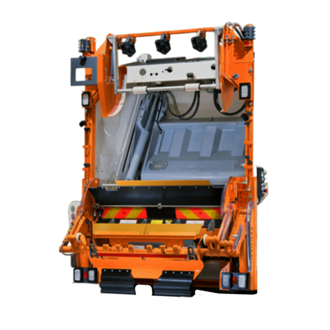
are automatic bin lifts that can be deployed for a wide range of uses.
They are not only suitable for emptying the commonly used 2-wheel bins but also most 4-wheel containers.
The optional pick-up arms make it possible to empty refuse bins that are not fitted with a comb receiver pick-up
edge.
4
ãTerberg Machines B.V. IJsselstein, The Netherlands
All rights reserved. No part of this book may be reproduced, stored in database or retrieval system, or published, in any form or in any way,
electronically, mechanically, by print, photoprint, microfilm or any other means without prior written permission from the publisher.
1. 8 Position button control station R/H*
2. 8 Position button control station L/H*
3. Safety arm
4. Startsensor
5. Pick-up comb
AB
11. Sensor 4-wheel container recognition
12. Diagnostic System*
13. Light screen (option)
6. Bin security switch
7. Hopper plate
8. Emergency stop
9. Catcherbar / Lid opener
10. Bin guide plate
2
1
* Depending on the country: - The L/H and R/H control stations are interchanged.
- The Diagnostic System is placed on the L/H or R/H side of the bin lift.
IN pick-up arms can
also be fitted as an option.

1.2 Technical specifications
Omni
DEL e
5
ãTerberg Machines B.V. IJsselstein, The Netherlands
All rights reserved. No part of this book may be reproduced, stored in database or retrieval system, or published, in any form or in any way,
electronically, mechanically, by print, photoprint, microfilm or any other means without prior written permission from the publisher.
2-wheel bins
4-wheel containers
flat lid
4-wheel containers
roll top
Paladin
containers
Capacity 80 - 360 litres 500 - 1280 litres 770 and 1100 litres 900 litres
According to standard EN 840-1 EN 840-2 EN 840-3 --
Lifting capacity 1600N (160 kg) 5000N (500 kg)
Cycle time (excl. dwell time) 6.0 seconds 11 seconds
Time in tipping position Adjustable Adjustable
Guidelines and standards 2006/42/EG, EN 1501-1 & EN 1501-5:2011
Weight 595 kg (depending on configuration)
Noise levels ≤ 65 dB(A)
Vibrations ≤ 2.5 m/s2
Operating voltage 24 Volts
Maximum current consumed by control 10 Amps
Oil flow 40-60 litres/minute
Working pressure PTO Min. 180 bar / Max. 250 bar
Return pressure Max. 2.0 bar
Quick release couplings IN 25, ISO 72141-1
2-wheel bins 4-wheel containers
flat lid
Capacity 80 - 360 litres 500, 660 and 770 litres
According to standard EN 840-1 EN 840-2
Lifting capacity 1000N (100 kg) 3500N (350 kg)
Cycle time (excl. dwell time) 6.0 seconds 11 seconds
Time in tipping position Adjustable Adjustable
Guidelines and standards 2006/42/EG, EN 1501-1 & EN 1501-5:2011
Weight 655 kg (depending on configuration)
Noise levels ≤ 58 dB(A)
Vibrations ≤ 2.5 m/s2
Operating voltage 24 Volts
Maximum current consumed by control 10 Amps
Average power consumption during normal daily use 20 Ah
Average electrical power 2-wheel bin 1.8 kW
Maximum electrical power 2-wheel bins (1000N) 3.6 kW
Maximum electrical power 4-wheel containers (5000N) 5.2 kW
Omni
DEL
Bins/containers to be emptied, “teardrop” catcherbar
Bins/containers to be emptied, 2-position catcherbar / lid opener
The emptying of bin/container types other than
those indicated above, is not permitted with
this bin lift system. If in doubt, please contact
your distributor.

2. Safety
2.1 General safety instructions
-The bin lift may only be operated by persons who have received operator training and are fully familiar with
the working of the bin lift.
- Read the operating instructions carefully before taking the bin lift into service.
- Read the instructions for the compactor carefully.
- The bin lift may not be operated under any circumstances if the oil flow is greater than 60 litres/minute.
- o not use the bin lift in areas or near installations where there is a risk of fire and/or explosion due to the
presence of gases and/or combustible substances.
- You will be working where traffic is present during your daily work as operator of the bin lift.
o not endanger yourself or other road users during your daily operations with the bin lift.
- Before commencing the run discuss and agree with your colleagues how to act in particular situations such as
stopping, driving away, etc.
- When you are working with the bin lift system you may not wear any loose hanging clothing or jewellery.
- Always wear work clothing, safety shoes and work gloves that comply with the standards shown in the table
below while working with the bin lift.
- Make sure that an unattended bin lift can never be started by a person who is not authorised to do so
(remove ignition key whenever the vehicle is left unattended).
- Technical faults must be reported immediately to the person who is responsible for the supervision of the bin
lift. The bin lift must be put out of action until the fault (that could cause danger) has been repaired.
- Never use the lifting chair or other parts of the bin lift system as a seat,
this is life threatening!
- Under no circumstances may the controls be changed.
- Under no circumstances may any of the safety provisions fitted be removed or changed.
- If the safety provisions are damaged they must be repaired or replaced immediately by original parts.
- Under no circumstances may the cycle speeds set by the manufacturer be changed.
- Under no circumstances may the lifting forces set by the manufacturer be changed.
- Operating and safety decals must be present and properly legible.
- Actions that override the safety provisions are expressly forbidden!
- The lifting chairs should be positioned in their travel position before reversing.
- It is not permitted to stand on the footboards while the refuse collection vehicle is reversing.
- Make sure that you are visible to the driver of the refuse collection vehicle when it is reversing.
2.2 Safety instructions applying while using the bin lift system
- Make sure that there are no persons in the immediate vicinity of the bin lift during the loading cycle.
- When the bin lift system is operating, under no circumstances is it permitted to put your hand in the bin lift
system (Risk of injury!).
- In the event of danger immediately press the nearest emergency stop switch.
- It is not permitted to work with bin/container types other than those stated in the manual.
- Check that there are no foreign objects in or between the bin lift system that could obstruct its working.
- It is not permitted to load / insert loose waste over the bin lift while the bin lift is operating automatically.
- Compacting may not be carried out when there are objects sticking out of the throw-in opening.
- Nothing should protrude from the bin/container.
- Keep the lid closed.
Personal protection equipment: According to standard:
Work clothing NEN-EN-ISO 20471:2013
Safety shoes NEN-EN-ISO 20345:2011
Work gloves NEN-EN 420:2003+A1:2009
6
ãTerberg Machines B.V. IJsselstein, The Netherlands
All rights reserved. No part of this book may be reproduced, stored in database or retrieval system, or published, in any form or in any way,
electronically, mechanically, by print, photoprint, microfilm or any other means without prior written permission from the publisher.

7
- Only empty bins that have the lid fully closed.
- o not empty damaged bins/containers.
- Bins/containers that are too heavy must not be lifted:
maximum lifting capacity 2-wheel bins: 1600N (160kg)
maximum lifting capacity 4-wheel containers “teardrop” catcherbar: 3500N (350kg)
maximum lifting capacity 4-wheel containers two position catcherbar: 5000N (500kg)
-Let go of the bin/container as soon as it is lifted.
- Check that the bin/container is positioned correctly on the pick-up comb before emptying it.
- Because the bin security switch is out of action during manual operation you must check extra carefully that
the bin/container is located properly on the pick-up comb.
- It is forbidden to manually assist the lifting cycle by hand.
- Only apply extra shaking if there is a need for this.
- Only take the bin/container away when it is back on the ground.
- o not take the bin/container away until the bin lift has come to a standstill.
- Place empty bins/containers where they will not cause a danger to other road users.
- It is forbidden to empty bins/containers containing hazardous and/or radioactive substances.
- It is forbidden to empty bins/containers containing smouldering or burning substances.
- o not use the bin lift system in situations where there is poor visibility of the bin lift.
- Never walk backwards in the direction of the bin lift system.
- Two bin presenting and/or taking at a time by one person should be kept to a minimum.
- When using the bin lift in extreme weather conditions the bin lift should be handled with care.
- If the bin lift is contaminated by weather conditions it must be cleaned.
- uring winter conditions, if the bin lift is contaminated by heavy snow or ice deposition on mechanical parts
or various sensors, the system can get clogged up.
Apply stop switch prior to cleaning. Clean these parts and keep as dry as possible. For example with a broom.
Never clean the bin lift using defrosting liquids!
2.3 Safety instructions applying during maintenance and
while carrying out repairs
- Maintenance and carrying out of repairs is only permitted for qualified technical personnel.
- Faults that have been observed must be repaired before the bin lift is taken back into service.
- uring maintenance and repair work switch off the bin lift (switch off the engine of the collection vehicle and
the main power switch).
- uring repair work it must be made impossible for unintentional switching on to occur, therefore remove the
ignition key from the ignition switch.
- Make sure that the lifting chairs are adequately supported when working under the chairs.
- Switch off the drive of the refuse collection vehicle before beginning cleaning.
- It is possible that grease can squirt out from the hinge points when a high pressure cleaner is used, protect
your eyes by always wearing safety glasses.
- Use the lifting points provided to raise the bin lift.
- Remember that the hydraulic system is filled with hydraulic oil under pressure, when working on the hydraulic
system. Always use personal protection equipment to prevent contact with the skin and eyes.
Use collecting trays to prevent pollution of the environment.
- You must keep to the maintenance intervals prescribed by the manufacturer.
- Electrical fuses must never be bridged or replaced by a fuse with higher capacity.
- When dismantling disconnect the bin lift from the vehicle using the plugs and quick release couplings intended
for this purpose.
- amaged safety and instruction decals must be replaced immediately.
ãTerberg Machines B.V. IJsselstein, The Netherlands
All rights reserved. No part of this book may be reproduced, stored in database or retrieval system, or published, in any form or in any way,
electronically, mechanically, by print, photoprint, microfilm or any other means without prior written permission from the publisher.

8
2.4 Warning signs
All safety and instruction decals must be replaced when damaged.
The pictogram decals have the following meaning:
o not stand under the lifting chair!
o not stand in working area!
o not put your hand in the bin lift; risk of injury!
o not stand under the lifting chair! (on safety arm L/H)
o not stand under the lifting chair! (on safety arm R/H)
ãTerberg Machines B.V. IJsselstein, The Netherlands
All rights reserved. No part of this book may be reproduced, stored in database or retrieval system, or published, in any form or in any way,
electronically, mechanically, by print, photoprint, microfilm or any other means without prior written permission from the publisher.

9
3. Transport and storage
3.1 General
- Check the position of the centre of gravity of the bin lift when raising this with a forklift truck or tackle.
- When dismantling disconnect the bin lift from the vehicle using the plugs and quick release couplings intended
for this purpose.
- Protect the 16-pole connecting plugs from water.
- Connect the hydraulic couplings together.
- Weight: OmniDEL: 595 kg (depending on configuration)
OmniDEL e: 655 kg (depending on configuration)
- Use a mobile hoist with minimum lifting capacity of 1000 kg and a hoist beam.
- Raise the bin lift using the lifting points provided.
- Lay the bin lift flat on the ground.
ãTerberg Machines B.V. IJsselstein, The Netherlands
All rights reserved. No part of this book may be reproduced, stored in database or retrieval system, or published, in any form or in any way,
electronically, mechanically, by print, photoprint, microfilm or any other means without prior written permission from the publisher.
Min. 1000 kg
1961
363

10
ãTerberg Machines B.V. IJsselstein, The Netherlands
All rights reserved. No part of this book may be reproduced, stored in database or retrieval system, or published, in any form or in any way,
electronically, mechanically, by print, photoprint, microfilm or any other means without prior written permission from the publisher.
4. Installation and commissioning
4.1 Dimensions of the bin lift
1774
935
(Veiligheidsarmen ingeklapt)
19961200 mm is ideaal
1364
500
1767
1504
300
(Safety arms folded)
1200mm ideal

11
ãTerberg Machines B.V. IJsselstein, The Netherlands
All rights reserved. No part of this book may be reproduced, stored in database or retrieval system, or published, in any form or in any way,
electronically, mechanically, by print, photoprint, microfilm or any other means without prior written permission from the publisher.
- ree space from the edge of the hopper plate ≥ 850mm.
≥850
172
191
- Necessary space for tilted 120 litre 2-wheel bin.

12
ãTerberg Machines B.V. IJsselstein, The Netherlands
All rights reserved. No part of this book may be reproduced, stored in database or retrieval system, or published, in any form or in any way,
electronically, mechanically, by print, photoprint, microfilm or any other means without prior written permission from the publisher.
56
341
915
555
- Necessary space for tilted 770 litre 4-wheel container flat lid.
- Necessary space for tilted 1100 litre 4-wheel container roll top.

13
ãTerberg Machines B.V. IJsselstein, The Netherlands
All rights reserved. No part of this book may be reproduced, stored in database or retrieval system, or published, in any form or in any way,
electronically, mechanically, by print, photoprint, microfilm or any other means without prior written permission from the publisher.
4.2 Assembly of the bin lift system on the body of the refuse collection vehicle
Tools required:
-Spanners/ring spanners 10, 19 and 24 mm.
-Mobile hoist/crane with minimum lifting capacity 1000 kg.
-Hoist beam with chains.
- Make sure that the refuse collection vehicle on which the bin lift is
being mounted is standing on a level surface.
- Switch off the engine of the refuse collection vehicle and remove the
ignition key from the ignition switch (keep on your person).
- Fit the supports (A) for the bin lift to rest on at the correct height at
the back of the refuse collection vehicle.
- Fit a guide plate between these supports at a minimum angle of 45°; this plate is to guide the tipped waste
into the hopper.
- Make sure that the lifting chairs are in the lowest position before beginning to lift.
- Connect the bin lift to a hoist beam.
- Raise the bin lift to build-on height using a lifting installation with minimum lifting capacity of 1000 kg.
- Position the bin lift on the assembly supports (A).
- Fix the bin lift to the assembly frame on the refuse
collection vehicle using M16 bolts (class 8.8), lock nuts and
washers ( IN 6340) with a tightening torque of 200 Nm.
* Build on height for loaded vehicle,
minimum: 1140mm
maximum: 1200mm
Terberg Machines B.V. recommends: 1200mm.
When mounting the bin lift on the compaction
body standard EN 1501-5 shall be observed.
Ensure that the support is strong enough to
bear the load of the bin lift system plus the
weight of a full bin/container (max. total weight).
420
955
1457
1895
0
min.45°
1410
1536
AA
1140 - 1200 mm*
Ø18
BACK O RE USE
COLLECTION VEHICLE
DETAIL of support (A)

14
ãTerberg Machines B.V. IJsselstein, The Netherlands
All rights reserved. No part of this book may be reproduced, stored in database or retrieval system, or published, in any form or in any way,
electronically, mechanically, by print, photoprint, microfilm or any other means without prior written permission from the publisher.
4.3 Safety light screen (optional)
In some body and chassis configurations it is impossible to keep to the 850mm distance as described in
NEN-EN-ISO 13857:2008. In these cases it is possible to stop the compactor using an interlock in accordance
with standard NEN-EN-ISO 14119:2013. The safety light screen provides such an interlock.
Working principle
A single ray light screen is fitted in the opening of the bin lift hopper. The compactor is stopped as soon as the
light ray is interrupted. This occurs both by the movement of a single lifting chair through the light ray and if a
person or object is in the danger zone.
The function of the light screen is switched off when both lifting chairs reach a height of 140cm above ground
level. From that moment the chair, in the way it is designed, blocks access to the hopper.
Extra compacting
Because of the extra interruptions to the compactor system the bin lift sends the compactor system an additional
single starting pulse. As soon as the lifting chair lowers down during the automatic cycle, the compactor carries
out one extra movement.
4.4 Coupling greasing system to a body greasing system (optional)
The optional available centralized greasing system of the OmniDEL and OmniDEL e is suitable for coupling to a
Progressive Greasing System.
* When using NLGI grade 0 grease - 10 cm3/10 uur
- Check the grease pump fitted and order the necessary parts.
- If additional information is necessary contact the supplier of the greasing system.
- Install an extra piston pump element on the housing of the grease pump.
- Fit a 6mm grease pipe if the distance between the grease pump and the bin lift is less than 10 metres. If the
distance is greater than 10 metres a 10mm grease pipe must be used.
- Check the working of the greasing system as soon as it has been fitted.
Technical specifications Progressive Greasing System:
Type of grease NLGI grade 2
Maximum pump pressure 300 bar
Minimum capacity 10 cm3/20 hours*

15
ãTerberg Machines B.V. IJsselstein, The Netherlands
All rights reserved. No part of this book may be reproduced, stored in database or retrieval system, or published, in any form or in any way,
electronically, mechanically, by print, photoprint, microfilm or any other means without prior written permission from the publisher.
4.5 Assembly advice footboards (optional)
2382
1200 mm is ideaal
450
500
2000
300
450
≤ 450
350
If the bin lift is fitted with a weighing system
the space between the footboard and the
weighing computer must be checked: this
must be ≥ 2000 mm (standard EN 1501-5).
The sensors of the footboards must be
connected according to the recommandation
of the body manufacturer.

16
ãTerberg Machines B.V. IJsselstein, The Netherlands
All rights reserved. No part of this book may be reproduced, stored in database or retrieval system, or published, in any form or in any way,
electronically, mechanically, by print, photoprint, microfilm or any other means without prior written permission from the publisher.
4.6 Hydraulic connection Omni
DEL
Check that the oil supply is never greater than 60 litres/min. If the oil flow is greater than 60 litres/min. the
supplier of the refuse collection vehicle body must be contacted.
- Clean the hydraulic quick release couplings of the bin lift and the refuse collection vehicle before connecting them.
- Couple the hydraulic quick release couplings from the bin lift to those on the body: the male coupling piece
on the bin lift is the return connection. Make sure that the couplings are fitted properly into each other so
that leakages and consequent damage are prevented.
- Remember that the hydraulic system is filled with hydraulic oil under pressure when working on the hydraulic
system.
- The hydraulic couplings on the bin lift are positioned at the top right of the bin lift.
- The quick release couplings are in accordance with:
N25A
ISO72141-1
- The return connection is fitted with a hydraulic hose ø22 mm and length 1250 mm.
4.7 Hydraulic connection Omni
DEL e
- The OmniDEL e does not have a hydraulic coupling to the body of the refuse collection vehicle.
- In order to profit in the best possible way from the lower fuel consumption check that there is no
hydraulic pump and hydraulic piping connected to supply an hydraulic bin lift.
Hydraulic couplings
The bin lift may not be taken into use with an
oil supply of more than 60 litres/min under
any circumstances!
Always use personal protection equipment to
avoid contact with the skin and eyes.
Before starting to use the bin lift system, first
read the operating instructions.
Use absorbents to avoid polluting the
environment.

17
ãTerberg Machines B.V. IJsselstein, The Netherlands
All rights reserved. No part of this book may be reproduced, stored in database or retrieval system, or published, in any form or in any way,
electronically, mechanically, by print, photoprint, microfilm or any other means without prior written permission from the publisher.
4.8 Electrical connection to compactor body: Omni
DEL
and Omni
DEL e
The connection between the bin lift and the body of the refuse collection vehicle is in accordance with
standard EN 1501-5.
Check the following points before making the connection:
- Start the vehicle and switch on the compactor.
- Press the compactor system start button.
The compactor must now operate as a “hold to run” system; as soon as the start button of the
compactor installation is released the compactor must stop.
- Check that the emergency stop switches of the compactor installation are working properly and that the
emergency stop buzzer in the cabin also works.
- Reset the emergency stop switches and check again that the compactor works as a “hold to run” system.
- Separate the 16-pole plug from the 16-pole fixed socket.
- Connect the body plug into the fixed socket on the bin lift.
- Connect the bin lift plug to the fixed socket on the body.
Electrical plugs and socket boxes
ake sure that the work area of the compac-
tion mechanism is sufficiently protected.
The following work may only be carried out by
qualified personnel.

18
ãTerberg Machines B.V. IJsselstein, The Netherlands
All rights reserved. No part of this book may be reproduced, stored in database or retrieval system, or published, in any form or in any way,
electronically, mechanically, by print, photoprint, microfilm or any other means without prior written permission from the publisher.
4.8.1 Explanation of cable loom connection pins
16-pole plug cable loom pin / wire definitions from bin lift
* CleAN open is a CAN data protocol for refuse collection vehicles; it makes data communication possible between the
various components (bin lift, identification system, weighing system and suchlike) of the refuse collection vehicle.
16-pole plug contact side
1
9
2
10
3
11
4
12
5
13
6
14
7
15
8
16
Pin number: Signal type: Signal description: Observation:
1Supply Power supply in +24 V, direct from chassis,
5 Amps maximum
2Supply Power supply in +24 V, direct from chassis,
5 Amps maximum (linked with pin 1)
3Gnd Ground Mass chassis, 3 Amps maximum
4Gnd Ground Mass chassis, 3 Amps maximum
(linked with pin 3)
5Input Reverse gear engaged +24 V
6Output Chairs low position,
out of travel position +24 V
7Bus CleAN open* CAN (L)
8Input Emergency stop circuit 1 Loop 1, input from the RCV,
maximum 300 mAmps and 50 V
9Output Emergency stop circuit 1 Loop 1, output to RCV,
maximum 300 mAmps and 50 V
10 Input Emergency stop circuit 2 Loop 2, input from RCV,
maximum 300 mAmps and 50 V
11 Output Emergency stop circuit 2 Loop 2, output to RCV,
maximum 300 mAmps and 50 V
12 Output Bin count pulse (one pulse per bin,
no matter if 2- or 4-wheeled) +24 V, 300ms 1 sec. maximum
13 Input “RCV” ready Body is in working order, lifter can use
revs and oil.
14 Output Hydraulic supply request and
engine speed request (+24 V)
15 Bus CleAN open CAN (H)
16 Output Start compaction cycle +24 V, 300ms 1 sec. maximum

19
ãTerberg Machines B.V. IJsselstein, The Netherlands
All rights reserved. No part of this book may be reproduced, stored in database or retrieval system, or published, in any form or in any way,
electronically, mechanically, by print, photoprint, microfilm or any other means without prior written permission from the publisher.
16-pole plug fixed socket pin / wire definitions on bin lift
8
16
7
15
6
14
5
13
4
12
3
11
2
10
1
9
Pin number: Signal type: Signal description: Observation:
1Input RCV in neutral gear = +24 V 16 to 34 V
2Not connected Info no bin lift fitted
3Output Safe distance from footboard level
4Output Safe distance from footboard level
5Input Footboards OCCUPIE 0V
6Output Clash between bin lift and packer plate
(info to RCV that container is within
reach of packer plate).
+24 V = packer plate stops, as soon as
the container is out of reach of the
packer plate an extra start signal
compaction cycle is given.
7Bus CleAN open CAN (L)
8Not connected
9Not connected
10 Not connected
11 Not connected
12 Input Emergency stop control system:
normal “safe” state = +24 V Maximum 3 Amps
13 Output Signal hopper plate switch (OK = +24 V).
Safety distance okay from ground level.
14 Input Clash between packer plate and bin lift
(info to bin lift that packer plate is within
reach of container).
+24 V = bin lift stops in horizontal
position out of reach of the packer plate.
15 Bus CleAN open CAN (H)
16 Output Signal hopper plate switch (OK = +24 V).
Safety distance okay from ground level.
16-pole socket box contact side

20
ãTerberg Machines B.V. IJsselstein, The Netherlands
All rights reserved. No part of this book may be reproduced, stored in database or retrieval system, or published, in any form or in any way,
electronically, mechanically, by print, photoprint, microfilm or any other means without prior written permission from the publisher.
4.9 Battery connection Omni
DEL e
The OmniDEL e must be connected to the battery of the refuse collection vehicle using two 70mm2cables.
The Omni
DEL e
is electrically driven. Therefore, the following points must be taken into account:
Battery
Minimum battery capacity: 175 Ah
Terberg Machines recommends: 245 Ah
Alternator
The OmniDEL e requires 20 Ah, 24 Volt C from the alternator during normal daily operation.
Minimum alternator capacity: 75 A
Terberg Machines recommends: 100 A
Position of the electrical connection on the bin lift
The bin lift is fitted with a two-pole plug at the top right of the bin lift.
- Start laying the cable from the 2-pin plug end after connecting to bin lift and securing in a safe none-vulnera-
ble position over the top of the compaction body, ensure any hinge point has suitable free cable to allow
movement. Pass the cable down between the body and cab on the side where the battery box is located.
- Make sure that the cable is not laid over any sharp edges.
- o not force the cable around sharp bends. The minimum radius (R) of a bend is 5 cm.
- Fix the cable at maximum intervals of 30 cm.
Plug battery connection
R
R
Before beginning to make the connection
switch off the main switch of the refuse
collection vehicle and/or disconnect the
negative terminal of the battery!
Vehicle manufacturers provide instructions as
to how extra power users are to be connected.
Always follow these instructions.
The pre-mounted cable set with the necessary
appendages can be ordered from Terberg
achines B.V. (
part number: 37501
)
Keep the cable as short as possible in order to
reduce weight and voltage drop to a minimum!
This manual suits for next models
1
Table of contents
Other Terberg Lifting System manuals
Popular Lifting System manuals by other brands

Anthony Liftgates
Anthony Liftgates ETU-20-44 installation manual

Maxon
Maxon DMD-22 instruction manual

Clarke
Clarke Strong Arm CML2 Operating & maintenance instructions

The Handy
The Handy 20707G INSTRUCTIONS, PARTS DRAWING, PART LIST

Shore Side Docks
Shore Side Docks 1200 instructions

Fantek
Fantek FT-6860 operating instructions