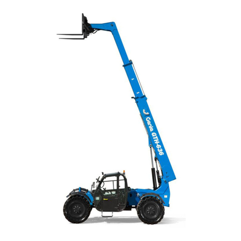
Terex Genie GTH-4013 User manual

CAUTION: THOROUGHLY READ AND UNDERSTAND THIS HANDBOOK BEFORE OPERATING THE MACHINE
CAUTION: KEEP THIS HANDBOOK IN THE MACHINE AT ALL TIMES
GTH-4013
Operator's manual
Part N. 57.0007.0200
Rev. 0 01/2006
From serial n. 14518
To serial n. 19104
English
Edition


Operator's manual 57.0007.0200 - GTH-4013
No part of this publication may be reproduced, stored in a retrieval system or transmitted in any form or by any means without
prior written permission from TEREXLIFT srl.
In pursuing a policy of constant quality improvement, TEREXLIFT srl reserves the right to make changes at any time and
without undertaking to give prior notice; therefore, also this publication may be subject to modifications.
Some photos or drawings have been used to illustrate a specific function; as a result, they may not refer to the machine
treated in this manual.
© Copyright 2006 TEREXLIFT srl - All rights reserved.
Produced by: TEREXLIFT Technical Literature Dept. - Studio VEGA - Forlì
Genie Scandinavia
Phone +46 31 575100
Fax +46 31 579020
Genie France
Phone +33 (0)2 37 26 09 99
Fax +33 (0)2 37 26 09 98
Genie Iberica
Phone +34 93 579 5042
Fax +34 93 579 5059
Genie Germany
Phone +49 (0)4202 88520
Fax +49 (0)4202 8852-20
Genie U.K.
Phone +44 (0)1476 584333
Fax +44 (0)1476 584334
Genie Mexico City
Phone +52 55 5666 5242
Fax +52 55 5666 3241
Genie North America
Phone 425.881.1800
Toll Free USA and Canada
800.536.1800
Fax 425.883.3475
Genie Australia Pty Ltd.
Phone +61 7 3375 1660
Fax +61 7 3375 1002
Genie China
Phone +86 21 53852570
Fax +86 21 53852569
Genie Malaysia
Phone +65 98 480 775
Fax +65 67 533 544
Genie Japan
Phone +81 3 3453 6082
Fax +81 3 3453 6083
Genie Korea
Phone +82 25 587 267
Fax +82 25 583 910
Genie Brasil
Phone +55 11 41 665 755
Fax +55 11 41 665 754
Genie Holland
Phone +31 183 581 102
Fax +31 183 581 566
TECHNICAL SERVICES

Revision Revised Issued
N. date pages Notes by
1
2
3
4
5
6
7
8
9
10
11
12
13
14
15
16
17
18
19
20
21
22
23
24
25
26
27
28
29
30
31
32
33
34
35
36
37
38
39
REVISED PAGE LIST

Handler with telescopic boom
GTH-4013
Document 57.0007.0200 - 01/2006
Page 1
■INTRODUCTION
This manual provides information for a safe and proper
operation and maintenance of the machine.
STRICTLY COMPLY WITH THE INSTRUCTIONS
GIVEN IN THIS HANDBOOK!
READ AND UNDERSTAND THIS HANDBOOK
BEFORE STARTING, USING AND CARRYING
OUT ANY OPERATION WITH AND ON THE
MACHINE.
The handbook is divided into seven sections:
Sect. A GENERAL INFORMATION
Sect B SAFETY PRECAUTIONS
Sect C OPERATING INSTRUCTIONS
Sect. D MAINTENANCE
Sect. E TROUBLESHOOTING
Sect. F OPTIONAL ATTACHMENTS
Sect. G TABLES AND ENCLOSURES
Section Acontains general concepts that are decisive
for the knowledge of the main parts of the machine.
It also contains all necessary data for a correct
identification of the machine, the technical features of
the machine, etc.
Section Bis especially addressed to the personnel,
who shall operate, repair and service the machine, and,
in case of companies with a wide fleet of machines, to
those responsible for safety.
It describes the essential compulsory qualities of the
personnel in charge and other important information
for the safety of persons and things.
Section Cis mainly addressed to the operators who
operate the machine. This section illustrates all control
devices.
Additionally, it contains the main use instructions -i.e.
engine starting, machine parking, machine storing.
Section Dis addressed to those responsible for
maintenance and the servicemen.
The section describes the maintenance schedule and
the relevant intervals.
Section E deals with the failure diagnostics.
Section Fmakes a list of the main interchangeable
attachments that can be coupled to the machine:
dimensions, weight, application field and limits of use.
Section Gcontains tables and various enclosed
documents like load charts, wiring diagrams, hydraulic
schemes, torque wrench setting table, etc.
Sections are subdivided into chapters and paragraphs
that are numbered progressively.
The quickest way to look for information is the reference
to the general index or the titles of the single chapters
and paragraphs that represent keys for an easy
consultation.
Take care of this manual and keep it in an
accessible place within the machine, even
after its reading, so that it will always be
within reach if in doubt.
If you are unsure about anything, please address to
GENIE Assistance Service or to your agent/dealer:
addresses, phone and fax numbers are printed in
the cover and in the title-page of this manual.
IMPORTANT
Any difference between the contents of this manual
and the real functional character of the machine
can be attributed to either a machine manufactured
before the issue of this manual or to a manual going
to be updated after some changed effected on the
machine.
Always contact GENIE Assistance Service for any
updated version of this manual and any additional
information.
INTRODUCTION
Document 57.0007.0200 - 01/2006
Page 2
Handler with telescopic boom
GTH-4013
■SYMBOLS
When using the machine, operators could have to face
some situations requiring special care and particular
knowledge.
When these situations involve the safety of operators
or bystanders, the machine efficiency and proper
utilisation, this handbook stresses these specific
instructions by means of SPECIAL SYMBOLS.
There are seven special (or safety) symbols in this
manual, always combined with keywords that class the
situations according to their danger degree.
The symbols are always followed by a text explaining
the situation taken into account, the attention to be
paid to such situation, the method and the behaviour to
be adopted. When necessary, it stresses prohibitions
or supplies instructions to prevent dangers.
Sometimes, it can be followed by illustrations.
We list below the special (or safety) symbols according
to the relative degree of a hazard:
Safety Alert symbol: when you see this symbol, be
alert to the possibility of personal injury. Strictly
obey all the safety messages accompanying this
symbol to avoid the risk of serious injury or death.
DANGER
Red: used to indicate an imminently hazardous
situation which, if not avoided, will result in death
or serious injury.
DANGER
Orange: used to indicate a potentially hazardous
situation which, if not avoided, could result in death
or serious injury.
CAUTION
Yellow with safety alert symbol: used to indicate a
potentially hazardous situation which, if not
avoided, may result in minor or moderate injury.
ATTENTION
Yellow without safety alert symbol: used to indicate
a potentially hazardous situation which, if not
avoided, may result in damage to the machine or
the systems.
PROTECT THE
ENVIRONMENT
Green: used to draw the attention to important
information on environment protection.
IMPORTANT
Green: used to indicate operation and maintenance
information.
WHEN READING THIS MANUAL, PAY THE
GREATEST ATTENTION TO THESE SPECIAL
SYMBOLS AND THE EXPLANATION OF THE
SITUATIONS THEY EMPHASIZE.
The manual in electronic format also contains the
following symbol:
which enables the user to return to the
table of contents
INTRODUCTION

Handler with telescopic boom
GTH-4013
Document 57.0007.0200 - 01/2006
Page 3
GENERAL INDEX
GENERAL INFORMATION Sect. A
SAFETY PRECAUTIONS Sect. B
OPERATING INSTRUCTIONS Sect. C
MAINTENANCE Sect. D
TROUBLESHOOTING Sect. E
OPTIONAL ATTACHMENTS Sect. F
TABLES AND DOCUMENTS ENCLOSED Sect. G
GENERAL INDEX

Document 57.0007.0200 - 01/2006
Page 4
Handler with telescopic boom
GTH-4013
INTENTIONALLY BLANK PAGE

Page A-1
GENERAL INFORMATION
Document 57.0007.0200 - 01/2006
Handler with telescopic boom
GTH-4013
Section A
GENERAL INFORMATION
TABLE OF CONTENTS
A-1 CONVENTIONAL REFERENCES................................................................................ A-2
A-1.1 Machine position ........................................................................................................ A-2
A-1.2 Labels and warning plates applied on the machine ................................................... A-3
A-1.3 Explanation of the different symbols used on the machine ....................................... A-10
A-2 MACHINE IDENTIFICATION....................................................................................... A-12
A-2.1 Machine model and type ............................................................................................ A-12
A-2.2 Manufacturer .............................................................................................................. A-12
A-2.3 Machine identification plates...................................................................................... A-12
A-2.4 CE marking ................................................................................................................. A-13
A-2.5 Chassis serial number ................................................................................................ A-13
A-2.6 Identification plates of the main parts ........................................................................ A-13
A-3 ALLOWED USE .......................................................................................................... A-14
A-3.1 Allowed use ................................................................................................................ A-14
A-3.2 Improper use .............................................................................................................. A-14
A-3.3 Residual hazards ........................................................................................................ A-14
A-3.4 Applicable standards.................................................................................................. A-15
A-3.5 Safety devices ............................................................................................................ A-16
A-4 GENERAL DESCRIPTION .......................................................................................... A-20
A-4.1 List of the main components ...................................................................................... A-20
A-4.2 Description of the main components ......................................................................... A-21
A-4.3 Optional accessories .................................................................................................. A-21
A-5 TECHNICAL DATA AND PERFORMANCE ................................................................. A-22
A-5.1 Main dimensions ........................................................................................................ A-22
A-5.2 Limits of use ............................................................................................................... A-22
A-5.3 Weight ........................................................................................................................ A-22
A-5.4 Speed ......................................................................................................................... A-22
A-5.5 Payload and reach...................................................................................................... A-23
A-5.6 Forks (floating type) .................................................................................................... A-23
A-5.7 Diesel engine .............................................................................................................. A-23
A-5.8 Electrical system ........................................................................................................ A-23
A-5.9 Machine sound levels ................................................................................................. A-23
A-5.10 Vibration levels ........................................................................................................... A-23
A-6 LIFETIME .................................................................................................................... A-24
A-7 ITEMS SUPPLIED....................................................................................................... A-24
A-7.1 Literature supplied...................................................................................................... A-24

Page A-2
GENERAL INFORMATION
Document 57.0007.0200 - 01/2006
Handler with telescopic boom
GTH-4013
A-1
CONVENTIONAL REFERENCES
■A-1.1 MACHINE POSITION
Conventionally the machine should be considered
positioned as shown in the figure.
This convention is necessary to make any reference of
this handbook to different machine parts (front, rear,
etc.) clear and unmistakable.
Any exception to this rule will always be specified.
RIGHT SIDE
LEFT SIDE
LOWER PART
UPPER PART
FRONT
PART
REAR PART

Page A-3
GENERAL INFORMATION
Document 57.0007.0200 - 01/2006
Handler with telescopic boom
GTH-4013
■A-1.2 LABELS AND WARNING PLATES
APPLIED ON THE MACHINE
This paragraph lists the labels and warning plates
normally applied on standard machines or on special
attachments coupled to the machine.
IMPORTANT
The familiarisation with these labels is never a
waste of time.
Make sure they are easy to read. For this purpose,
clean them or replace those that become
unreadable (either graphic or text).
To clean labels, use of a soft cloth, water and soap.
Never use solvents, petrol, etc.
When a label is applied on a part to be replaced,
make sure that the replaced part is already labelled
as required or apply a new label.
09.4616.0109
09.4618.0030
09.4618.0661
09.4618.0230
09.4618.0227
09.4618.0230
09.4616.0040
09.4618.0212
09.4618.0242
09.4618.0547
09.4618.0061
09.4618.0361
09.4618.0026
09.4618.0241
09.4618.0022
09.4618.0547
09.4618.0061
09.4618.0171

Page A-4
GENERAL INFORMATION
Document 57.0007.0200 - 01/2006
Handler with telescopic boom
GTH-4013
09.4618.0663
09.4618.0516
09.4618.0230
09.4618.0230
09.4618.0547
09.4618.0061
09.4618.0212
09.4618.0010
09.4618.0662
09.4618.0547
09.4618.0061
09.4618.0661
09.4618.0361
09.4616.0068
09.4618.0230
09.4618.0243
09.4618.0361

Page A-5
GENERAL INFORMATION
Document 57.0007.0200 - 01/2006
Handler with telescopic boom
GTH-4013
XX
Decal Code Description
09.4618.0022 Keep out of the working range of the machine.
When the machine is running, entering the working
range of the machine is prohibited.
09.4618.0212 Keep out of the working range of the machine.
When the machine is running, entering the working
range of the machine is prohibited.
Guaranteed sound power level. It indicates the
guaranteed sound power level measured in
accordance with the Directive 2000/14/EC.
09.4618.0516 Quick guide.
09.4618.0663 An overview of the operator's handbook concerning:
- control lever,
- machine starting,
- overload warning system
- main safety precautions.
The guide also includes the fork load charts with or
without use of the outriggers.
• Load chart for operations without outriggers (or
with outriggers up). It defines the exact working
limits of the machine (in terms of payload and
reach) to be strictly respected by the operator
when using the machine without outriggers (or with
retracted outriggers).
• Loadchartforoperations with outriggers down.
It defines the exact working limits of the machine
(in terms of payload and reach) to be strictly
respected by the operator when using the machine
with lowered outriggers.
3
4
KEEP OUT OF
WORKING RANGE

Page A-6
GENERAL INFORMATION
Document 57.0007.0200 - 01/2006
Handler with telescopic boom
GTH-4013
Decal Code Description
VIETATO APRIRE CON MOTORE IN MOTO
DO NOT OPEN WHILE ENGINE IS RUNNING
N'OUVRIR QU'A L'ARRET DU MOTEUR
ÖFFNEN NUR BEI STILLSTEHENDEM MOTOR
ABRIR SOLO CON MOTOR PARADO
PROIBIDO ABRIR COM O MOTOR LIGADO
VERBODEN KOFFERBAK TE OPENEN WANNEER DE MOTOR DRAAIT.
P max
kg/cm
2
XXX
09.4618.0010 Do not open while engine is running.
Do not open the engine bonnet when engine is
running, since this may result in serious injury due to
moving parts or hot components.
09.4618.0030 Do not change mechanical gear when the machine
is running.
09.4618.0026 Use limits close to electric power lines. It defines
the minimum distance to be kept when the machine
works close to aerial power lines.
09.4618.0361 Maximum pressure on the ground. The value
indicates the maximum pressure on the ground of the
outriggers to prevent the machine from sinking into
the ground and avoid instability.
09.4618.0227 Fork pitching. Warning for road circulation which
indicates the need to pitch back and block the forks.
CHANGE MECHANICAL
GEAR ONLY WHEN THE
MACHINE IS STATIONARY
DANGER
ELECTRIC CABLES AND
POWER LINES
KEEP EVERY PART OF THE MACHINE, LOADS AND
ACCESSORIES AT LEAST 6 METERS FROM
OVERHEAD POWER LINES

Page A-7
GENERAL INFORMATION
Document 57.0007.0200 - 01/2006
Handler with telescopic boom
GTH-4013
Decal Code Description
09.4618.0230 Warning stickers. Applied near coupling points,
silencer, fan belt, hydraulic oil level, tank, etc.
09.4618.0547 Tyre inflation sticker.
(standard) Placed near the wheels, this label shows the
recommended tyre inflation pressure.
09.4618.0061
(optional)
09.4618.0241 "GENIE" sticker.
09.4618.0242
09.4618.0243
09.4618.0661 "GENIE GTH-4013" sticker.
Anchorage points. Applied near the holes envisaged for
machine lifting.
Fuel cap. Applied near the engine oil cap.
Hydraulic oil. Applied near the hydraulic oil plug or level
indicator.
Engine oil level. Applied near the engine oil dipstick.
Moving gears. Applied near the fan of the heat exchanger.
Unscrew the plug with extreme caution: hot water.
Risk of burns! Warns the operator of the risk of burns
when unscrewing the plug of the compensation tank of the
heat exchanger.
Hot surfaces. Risk of burns. Applied on those surfaces
which during operation can become hot and cause burns.
Risk of crushing injury to the hands. Use extreme
caution when moving the outriggers.
Presence of moving parts. Use extreme caution when
moving the outriggers.
GTH-4013
P= bar
5,5
P=
bar
4,5

Page A-8
GENERAL INFORMATION
Document 57.0007.0200 - 01/2006
Handler with telescopic boom
GTH-4013
Kg 4000
Decal Code Description
__._____._____
.............
______
____
___
MODELLO - TYPE - DÉSIGNATION
MODELL - MODELO
ANNO DI COSTRUZIONE -
YEAR OF CONSTRUCTION -
ANNÉE DE CONSTRUCTION -
BAUJHAR - AÑO DE CONSTRUCCIÓN
MASSA - MASS - MASSE -
MASSE - MASA
PORTATA NOMINALE - PAY LOAD -
PORTEE NOMINALL - NENN
TRAGFÄHIGKEIT - CARGA NOMINAL
CENTRO DI GRAVITÀ - CENTER OF
GRAVITY - CENTRE DE GRAVITÉ -
SCHWERPUNKT - CENTRO DE GRAVEDAD
____
___
CENTRO DI CARICO - LOAD CENTER -
CENTRE DE CHARGE - LASTPUNKT -
CENTRO DE CARGA
MODELLO MACCHINA - MACHINE MODEL -
DESOGNATION MACHINE - MASCHINEN MODELL
MODELO MÁQUINA
N°SERIE - SERIAL N°-N°DES ERIE
- SERIEN N°-N°DE BASTIDOR
JUNTO HORQUILLAS
GROUPE FOURCHES-GABELGROUPPE
ASSIEME FORCHE-FORKS ASSY
TEREXLI FT
s.r.l.
ZONA INDUSTRIALE - 06019 UMBERTIDE (PG) - ITALY
Tel. +39 (0)75 94181 Fax +39 (0) 75 9415382
200
kgkg
kg
kg
TEREXLIFT srl - ZONA INDUSTRIALE - 06019 UMBERTIDE (PG) - ITALY
Tel. (075) 941.811 Fax (075) 941.53.82 Telex 66106 ITALMA I
MODELLO - MODEL - MODELE - TYP - MODELO
ANNO DI COSTRUZIONE - YEAR OF MANUFACTURE - ANNEE DE FABRICATION
BAUJAHR - AÑO DE FABRICACIÓN
MATRICOLA - SERIAL N. - N. DE SERIE - FZ.-IDENT NR. - NO. DE SERIE
OMOLOGAZIONE
FABBRICATO IN ITALIA - MADE IN ITALY
PESO MAX ASSALE ANT. - MAX FRONT AXLE WEIGHT - POIDS MAX ESSIEU AVANT
ZUL. ACHSLAST VO. N. ST VZO - PESO MAX EJE ANTERIOR
PESO MAX ASSALE POST. - MAX REAR AXLE WEIGHT - POIDS MAX ESSIEU ARRIERE
ZUL. ACHSLAST HI. N. ST VZO - PESO MAX EJE POSTERIOR
PESO TOTALE - TOTAL WEIGHT - POIDS TOTAL - ZUL. GESAMTGEWICHT N. ST VZO
PESO TOTAL
MATRICOLA MOTORE TERMICO - ENGINE SERIAL N. - N. MOTEUR THERMIQUE
FABRIK NR. DIESEL MOTOR - NO. DE SERIE MOTOR TERMICO
09.4616.0040 Max capacity. Indicates the maximum capacity of
the machine.
09.4616.0068 Machine data plate. The identification plate contains
the main identification data of the machine.
09.4616.0109 Fork data plate. This plate shows the main data of
the fork installed on the machine.
ROPS-FOPS cab type-approval plate. This plate
shows the type-approval data of the driving cab
according to ROPS - FOPS regulations.
09.4618.0171 Re-sequencing the telescopic boom extension. If,
during normal operation, a change in the boom
extended lengths is noticed, proceed with re-
sequencing as indicated in the operator’s manual.
ATTENTION
TO PREVENT DAMAGE OF INTERNAL
BOOM HOSES BOOM SECTIONS NEED
TO BE EXTENDED EQUALLY OTHERWISE
RE-SEQUENCING WILL BE REQUIRED.
SEE OPERATORS MANUAL FOR MORE
DETAILS.
09.4618.0171

Page A-9
GENERAL INFORMATION
Document 57.0007.0200 - 01/2006
Handler with telescopic boom
GTH-4013
Decal Code Description
09.4618.0514 Caution: accumulator under pressure.
09.4618.0673 Emergency controls. Reminds the operator the
correct procedure for the manual operation of the
mainvalveinan emergency. It also shows the controls
and the relevant controlled movements of all the
levers of the main valve.
IN ATTESA DA
TEREX
ATTENZIONE!
CAUTION!
RECIPIENTE IN PRESSIONE
HIGH PRESSURE ACCUMULATOR

Page A-10
GENERAL INFORMATION
Document 57.0007.0200 - 01/2006
Handler with telescopic boom
GTH-4013
■A-1.3 EXPLANATION OF THE DIFFERENT
SYMBOLS USED ON THE MACHINE
This paragraph illustrates those symbols that are
normally applied on the main control devices and
instruments of a standard machine, and those that can
be applied on accessories or special attachments.
They are mainly (ISO) standardised symbols that are
now part of the common life. But we consider useful to
explain them once again.
Symbol Description
IMPORTANT
Spend the necessary time to become familiar with
these symbols and to learn their meaning.
Hazard warning lights
Windscreen washer
Cab ventilation fan
Diesel engine water temperature
Fuel level
Hydraulic oil temperature
Position lights
High beam
Low beam
Fog lamp
Turn signals
Parking brake
Symbol Description
Battery charge
Attachment pushbutton (if any)
Steering mode switch
Brake pressure
Engine oil pressure
Boom up
Boom down
Boom out
Boom in
Attachment locked
Attachment unlocked
Fork pitching forward
Fork pitching back
Right outrigger down

Page A-11
GENERAL INFORMATION
Document 57.0007.0200 - 01/2006
Handler with telescopic boom
GTH-4013
Right outrigger up
Left outrigger down
Left outrigger up
Sway right
Sway left
Machine sway control
Cab controls
Platform controls
Road setting
Oil filter clogged
Air filter clogged
Speed selector switch
1st speed engaged
2nd speed engaged
Symbol Description Symbol Description
Lifting point
Emergency pump

Page A-12
GENERAL INFORMATION
Document 57.0007.0200 - 01/2006
Handler with telescopic boom
GTH-4013
A-2 MACHINE IDENTIFICATION
IMPORTANT
Check that the operator handbook refers to the
delivered machine.
When asking for information or technical
assistance, always specify model, type and serial
number of the machine.
■A-2.1 MACHINE MODEL AND TYPE
Handler with telescopic boom:
❑model GTH-4013
■A-2.2 MANUFACTURER
TEREXLIFT srl
Zona Industriale (Ind. Estate) - I-06019 UMBERTIDE
(PG) - ITALY
Enrolled in the register of companies at the Court of
Perugia under no. 4823
C.C.I.A.A. n°102886
Fiscal Code/V.A.T. no. 00249210543
■A-2.3 MACHINE IDENTIFICATION PLATES
The following data plates are applied on the machine.
Machine data plate
The identification plate contains the main identification
data of the machine like model, serial number and year
of manufacture.
On machines destined for the Italian market, the data
plate is installed in the driving cab, on the right, and
iswell-visible when the door isopened.Onthe machines
destined for foreign markets, the data plate is applied
on the front right side of the chassis.
200
kgkg
kg
kg
TEREXLIFT srl - ZONA INDUSTRIALE - 06019 UMBERTIDE (PG) - ITALY
Tel. (075) 941.811 Fax (075) 941.53.82 Telex 66106 ITALMA I
MODELLO - MODEL - MODELE - TYP - MODELO
ANNO DI COSTRUZIONE - YEAR OF MANUFACTURE - ANNEE DE FABRICATION
BAUJAHR - AÑO DE FABRICACIÓN
MATRICOLA - SERIAL N. - N. DE SERIE - FZ.-IDENT NR. - NO. DE SERIE
OMOLOGAZIONE
FABBRICATO IN ITALIA - MADE IN ITALY
PESO MAX ASSALE ANT. - MAX FRONT AXLE WEIGHT - POIDS MAX ESSIEU AVANT
ZUL. ACHSLAST VO. N. ST VZO - PESO MAX EJE ANTERIOR
PESO MAX ASSALE POST. - MAX REAR AXLE WEIGHT - POIDS MAX ESSIEU ARRIERE
ZUL. ACHSLAST HI. N. ST VZO - PESO MAX EJE POSTERIOR
PESO TOTALE - TOTAL WEIGHT - POIDS TOTAL - ZUL. GESAMTGEWICHT N. ST VZO
PESO TOTAL
MATRICOLA MOTORE TERMICO - ENGINE SERIAL N. - N. MOTEUR THERMIQUE
FABRIK NR. DIESEL MOTOR - NO. DE SERIE MOTOR TERMICO
Table of contents
Other Terex Forklift manuals

Terex
Terex GTH-1256 AF User manual

Terex
Terex GTH08E-13522 User manual

Terex
Terex Genie GTH-1256 User manual

Terex
Terex Genie GTH1513B-2 User manual

Terex
Terex Genie GTH-1544 Installation and operating manual

Terex
Terex Genie GTH-1256 User manual

Terex
Terex Genie GTH-636 User manual

Terex
Terex Genie GTH10E-16000 User manual

Terex
Terex Telelift 3713 SX User manual

Terex
Terex GTH06E-13295 User manual