April 2017
6 GTH-1544 Part No. 57.0009.0610
Second Edition - Second Printing
General Safety
237605 A
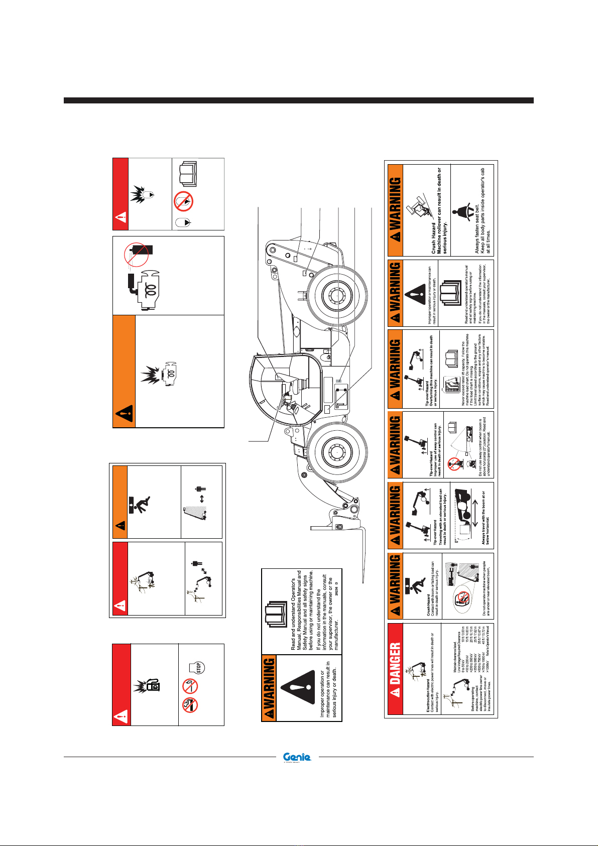
DANGER
Explosion / Burn Hazard
Battery explosion and/or contact with corrosive
acid will result in death or serious injury.
Wear personal protective equipment,
including face shield, gloves and long sleeve
shirt. Read manuals. If you do not understand
the information in the manuals, consult your
supervisor, the owner or the manufacturer.
237601 A
Keep all open flames and sparks away.
237601 A
97667 B
Burn Hazard
Contact with
hotsurfaces
can cause
burns.
Do not touch.
Allow surfaces
to cool before
servicing.
WARNING
97667 B
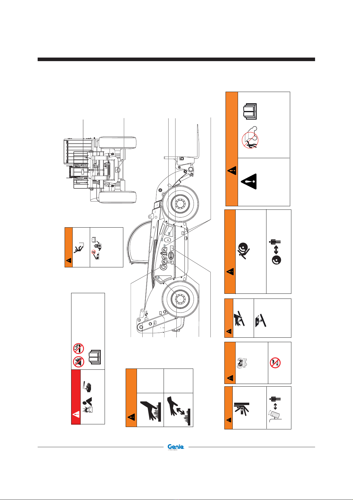
237598 A
Crush Hazard
Contact between wheel and chassis
can result in death or serious injury.
Stay clearofmachine during operation.
WARNING
237598 A
WARNING
Crush Hazard
Contact between wheel
and chassis can result in
death or serious injury.
Stay clear of machine
during operation. 237970 A
237970 A 82558 B
82558 B
Injection Hazard
Escaping fluid under pressure can
penetrate skin, causing serious injury.
Relieve pressure before disconnecting
hydraulic lines. Keep away from leaks
and pin holes. Use a piece of cardboard
or paper to search for leaks. Do not use
hand.
Fluid injected into skin must be
surgically removed within a few hours
by a doctor familiar with this type of
injury or gangrene will result.
WARNING
97667 B
215268 A
237601 A
214418 A
28175 H
97667 B
214418 A
97602 C
82558 B
237598 A
237970 A
237605 A
237605 A
WARNING
BurnHazard
Releaseof hot fluidunder
pressure can result in
deathor serious injury.
Do not loosen cap until
cool.
Compartment access
is restricted.
Contact with
components under
any cover may result
in serious injury.
Only trained maintenance personnel
should access compartments. Access
by operator is only advised when
performing Pre-operation Inspection.All
compartments must remain closed and
secured during operation.
28175 H
WARNING
28175 H
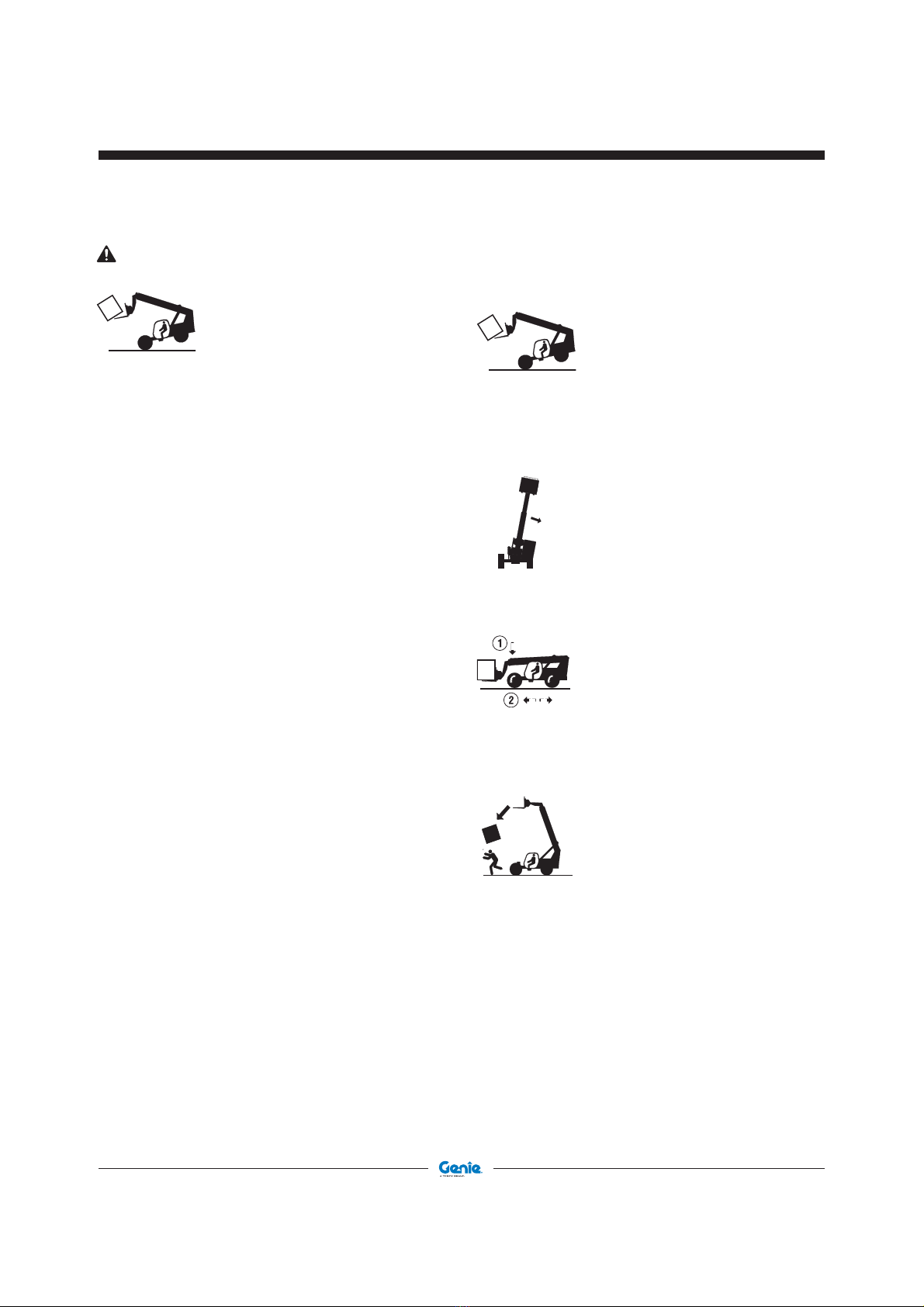
215268 A
FallHazard
Falling can result in death or serious injury.
When lifting personnel, only use a work platform
that meets Terex requirements, along with
associated machine load charts.
Besure to properly secureplatform to telehandler
beforeuse.
Readandunderstandoperator'smanual.
Wearapprovedpersonnelfallprotection
equipmentandattachlanyardtoanchorprovided.
WARNING
215268 A