Terumo T-SEAL III User manual

T-SEAL®III
Terumo Tube Sealing Device
Version 1.0
Operator’s Manual

UNLOCKING POTENTIAL |TERUMOBCT.COM Page 1of 15 Version 1.0 Rev 02/2021
©2021 Terumo BCT, Inc.
T-SEAL III
Terumo Tube Sealing Device
Operator’s Manual

UNLOCKING POTENTIAL |TERUMOBCT.COM Page 2of 15 Version 1.0 Rev 02/2021
©2021 Terumo BCT, Inc.
1. Warnings and Cautions 3
2. Scope 4
Introduction 4
Performance and Specifications 4
2.1 Symbols/Markings Description 9
3. Installation 10
Unpacking and Inspection 10
Environmental Requirements 10
3.1 Installation Procedure 10
Stand-Alone Setup 10
Cascade Setup 10
4. Functional Description 11
4.1 Description of Sealing 11
5. Operating Instructions 11
5.1 Preparation Before Use 12
5.2 How to Seal Tubes 12
6. Cleaning 12
6.1 Sealing Head 13
7. Troubleshooting 13
7.1 Sealer 13
8. Warranty and Service 14
8.1 Warranty 14
8.2 Service 14
8.3 Product Disposal 15

UNLOCKING POTENTIAL |TERUMOBCT.COM Page 3of 15 Version 1.0 Rev 02/2021
©2021 Terumo BCT, Inc.
1. Warnings and Cautions
The general safety information in the Operator’s Manual is for operating personnel. Specific notes, cautions, and
warnings are found throughout this document where applicable. Please read the Operator’s Manual carefully before
using this device.
Note! Identifies conditions that should be noted carefully.
Caution! Identifies conditions that could result in damage to the device.
Warning! Identifies conditions that could result in personal injury or loss of life.
Warning! T-SEAL III must be used in compliance with all specifications and operational procedures listed in the
Operator’s Manual.
Warning! T-SEAL III must be used under the control of trained personnel.
Warning! Follow the Operator’s Manual while operating T-SEAL III.
Warning! Cables and accessories other than those specified may result in increased emission or decreased
immunity of the equipment or system. Only accessories designed for use with T-SEAL III should be
used.
Warning! The device should not be used adjacent to or stacked with other equipment. If adjacent or stacked use
is necessary, verify normal operation of the device in the configuration in which it will be used.
Warning! If any of the components of T-SEAL III are exposed to blood, they must be cleaned with an
appropriate disinfectant solution.
Warning! The device must always be connected to a grounded outlet and with an appropriate alternating current
mains source, 100 or 240 V ~.
Warning! The device emits RF energy during the sealing procedure and movement of the electrode.
Warning! T-SEAL III is not intended for use in an oxygen-rich environment.
Warning! T-SEAL III is not intended to be used with flammable anesthetics or in conjunction with flammable
agents.
Caution! ELECTROMAGNETIC INTERFERENCE REGULATIONS
This device fulfills EN 60601-1-2:2014 Standards (Electromagnetic Compatibility). Nevertheless, this device uses
radiofrequency (RF) energy to generate heat while the tube is being sealed and can affect other Medical Electrical
Equipment. See Table 1 for guidance. If installation and use are not performed in accordance with the Operator’s
Manual, it could cause interference with radio, television, and instrument communications.

UNLOCKING POTENTIAL |TERUMOBCT.COM Page 4of 15 Version 1.0 Rev 02/2021
©2021 Terumo BCT, Inc.
2. Scope
This section contains a description of and specifications for T-SEAL III, a benchtop tube sealing device from Terumo
Blood and Cell Technologies (Terumo BCT).
Introduction
T-SEAL III is a fully automatic system for sealing polyvinyl chloride (PVC) tubes, especially those in blood pack
systems. Following the sealing procedure, the tube is easily pulled apart, due to the distinct sealing pattern, with no
damage to the blood inside the tube. Segments are formed by advancing the tube through the slot of the sealing head to
create a series of seals. Up to eight devices can be linked (cascaded) together for simultaneous sealing of segments.
T-SEAL III includes a built-in sealing head and is ready to operate. The front cover can be easily removed for cleaning.
T-SEAL III automatically adjusts the sealing time to suit different sizes and types of tubes.
T-SEAL III generates radio frequency (RF) energy for sealing. Be cautious of potential electrical shocks or hazards
while handling this device. Always turn the power switch off before disconnecting cables or cleaning.
Performance and Specifications
The table below lists the physical specifications.
Specification type
Value
Terumo BCT catalog
number
T3828
Description
T-SEAL III, a complete sealing system, which includes a built-in sealing head, a power
cord, and an operator’s manual
Type of tube
Polyvinyl chloride (PVC) tubes up to 6.2 mm (0.24 in) outer diameter with 4.4 mm
(0.17 in) inner diameter or 0.9 mm (0.04 in) wall thickness
Ethylene vinyl acetate (EVA) tubes up to 4.15 mm (0.16 in) outer diameter with 3.9 mm
(0.15 in) inner diameter or 0.9 mm (0.04 in) wall thickness
Sealing capacity
Up to 1000 seals/hour with PVC tubes up to 5 mm outer diameter (wall thickness
0.56 mm) at 20 °C (68 °F)
Sealing time
0.5 to 3 seconds, depending on tubing
Intended use
T-SEAL III is a fully automatic system for sealing blood bag system tubes. The sealing
is performed by means of a high-frequency dielectric heating system.
Input power
100-240 V ~, 50-60 Hz
Consumption
250 W
Power cord
Three-wire (10 A), 2.5-m cable with female plug (IEC 320)
RF output
80 W maximum/50 Ω/40.680 MHz
Size (W ×H ×D)
70 × 156 × 338 mm
Weight
2,8 kg (6,2 lb)
Temperature
Operating: 0 °C to 35 °C (32 °F to 95 °F)
Storage: -20 °C to 70 °C (-4 °F to 158 °F)
Humidity
Operating: 10% to 90% Rh (non-condensing)
Storage: 10% to 90% Rh (non-condensing)

UNLOCKING POTENTIAL |TERUMOBCT.COM Page 5of 15 Version 1.0 Rev 02/2021
©2021 Terumo BCT, Inc.
Altitude
Operating: Maximum 3000 meters (9842 feet)
In compliance with
EN 60601-1: 2006, General Requirements for basic safety and essential performance
EN 60601-1-2: 2015, Collateral standards for Electromagnetic Compatibility
Electrical safety:
Class I
Waterproof
IPX0. Not waterproof
T-SEAL III is used in the same environment as medical equipment (hospitals and blood banks). It must be used by
highly qualified personnel.
Manufacturer Conroy Medical AB
According to MDR: Valhallavaegen 1, SE-194 63 Upplands Vaesby, Sweden

UNLOCKING POTENTIAL |TERUMOBCT.COM Page 6of 15 Version 1.0 Rev 02/2021
©2021 Terumo BCT, Inc.
Table 1: Guidance and Manufacturer’s Declaration – Electromagnetic Emission
T-SEAL III is intended for use in the electromagnetic environment specified below. The customer or
the user of T-SEAL III should assure that it is used in such an environment.
Emission Test
Compliance
Electromagnetic Environment — Guidance
RF emission
CISPR 11
Group 2
T-SEAL III must emit electromagnetic energy in order to
perform its intended function. Nearby electronic equipment
may be affected.
RF emission
CISPR 11
Class B
T-SEAL III is suitable for use in all establishments, including
domestic establishments and those directly connected to the
public low-voltage power supply network that supplies
buildings used for domestic purposes.
Harmonic emission
IEC 61000-3-2
Class A
Voltage fluctuations/
Flicker emissions
IEC 61000-3-3
Complies
Table 2: Guidance and Manufacturer’s Declaration – Electromagnetic Immunity
T-SEAL III is intended for use in the electromagnetic environment specified below. The customer or
the user of T-SEAL III should assure that it is used in such an environment.
Immunity Test
IEC 60601
Test Level
Compliance
Electromagnetic
Environment — Guidance
Electrostatic
discharge (ESD)
IEC 61000-4-2
± 8 kV contact
± 15 kV air
8 kV
15 kV
Floors should be wood, concrete or
ceramic tile. If floors are covered with
synthetic material, the relative humidity
should be at least 30%.
Electrical fast
transient/burst
IEC 61000-4-4
± 2 kV for power
supply lines
2 kV
Mains power quality should be that of a
typical commercial or hospital
environment.
Surge
IEC 61000-4-5
± 1kV line(s)
to line(s)
± 2kV line(s)
to earth
1kV
2kV
Mains power quality should be that of a
typical commercial or hospital
environment.
Voltage dips, short
interruptions and
voltage variations
on power supply
input lines
IEC 61000-4-11
< 5% Uτ
(> 95% dip in Uτ)
for 0.5 cycle
40% Uτ
(60% dip in Uτ)
for 5 cycles
70% Uτ
(30% dip in Uτ)
for 25 cycles
< 5% Uτ
(> 95% dip in Uτ)
for 5 sec
< 5% Uτ
(> 95% dip in
Uτ)
for 0.5 cycle
40% Uτ
(60% dip in Uτ)
for 5 cycles
70% Uτ
(30% dip in Uτ)
for 25 cycles
< 5% Uτ
(> 95% dip in
Uτ)
for 5 sec
Mains power quality should be that of a
typical commercial or hospital environ-
ment. If the user of the T-SEAL III
requires continued operation during
power mains interruption, it is re-
commended that the T-SEAL III be
powered from an uninterruptible power
supply or battery.
Power frequency
(50/60 Hz)
magnetic field
IEC 61000-4-8
3 A/m
3 A/m
Power frequency magnetic fields should
be at levels characteristic of a typical
location in a typical commercial or
hospital environment.
NOTE Uτis the
AC mains voltage

UNLOCKING POTENTIAL |TERUMOBCT.COM Page 7of 15 Version 1.0 Rev 02/2021
©2021 Terumo BCT, Inc.
prior to application
of the test level.
Table 3: Guidance and Manufacturer’s Declaration – Electromagnetic Immunity
T-SEAL III is intended for use in the electromagnetic environment specified below. The customer or
the user of T-SEAL III should assure that it is used in such an environment.
Immunity Test
IEC 60601 Test Level
Compliance
Level
Electromagnetic Environment —
Guidance
Portable and mobile RF communications equipment should be used no closer to any part of
T-SEAL III including cables than the recommended separation distance calculated from the
equation applicable to the frequency of the transmitter.
Recommended separation distance:
Conducted RF
IEC 61000-4-6
Radiated RF
IEC 61000-4-3
10 Vrms
150 kHz to 80 MHz
10 V/m
80 MHz to 2.5 GHz
10 V
10 V/m
Portable and mobile RF
communications equipment should
be used no closer to any part of the
sealer, including cables, than the
recommended separation distance
calculated from the equation
applicable to the frequency of the
transmitter.
Where P is
the maximum output power rating of the transmitter in watts (W) according to the
transmitter manufacturer and d is the recommended separation distance in meters (m).
Field strengths from fixed RF transmitters, as determined by an electromagnetic site survey,ashould
be less than the compliance level in each frequency range.b
Interference may occur in the vicinity of equipment marked with the following symbol:
NOTE 1 At 80 MHz and 800 MHz, the higher frequency range applies.
NOTE 2 These guidelines may not apply in all situations. Electromagnetic propagation is affected by
absorption and reflection from structures, objects and people.
aField strengths from fixed transmitters, such as base stations for radio (cellular/cordless) telephones
and land mobile radios, amateur radio, AM and FM radio broadcast and TV broadcast cannot be
predicted theoretically with accuracy. To assess the electromagnetic environment due to fixed RF
transmitters, an electromagnetic site survey should be considered. If the measured field strength in
the location in which T-SEAL III is used exceeds the applicable RF compliance level above, it
should be observed to verify normal operation. If abnormal performance is observed, additional
measures may be necessary, such as reorienting or relocating T-SEAL III.
b
Over the frequency range 150 kHz to 80 MHz, field strengths should be less than 3 V/m.

UNLOCKING POTENTIAL |TERUMOBCT.COM Page 8of 15 Version 1.0 Rev 02/2021
©2021 Terumo BCT, Inc.
Table 4: Recommended Separation Distance Between Portable and Mobile RF Communications
Equipment and the T.3828 T-SEAL III
T-SEAL III is intended for use in the electromagnetic environment in which radiated RF
disturbances are controlled. The customer or the user of T-SEAL III can help prevent
electromagnetic interference by maintaining a minimum distance between portable and mobile RF
communications equipment (transmitters) and T-SEAL III.
For transmitters rated at a maximum output power, the recommended separation distance d in
meters (m) can be estimated using the equation applicable to the frequency of the transmitter, where
P is the maximum output power rating of the transmitter in watts (W) according to the transmitter
manufacturer
NOTE 1 At 80 MHz and 800 MHz, the higher frequency range applies.
NOTE 2 These guidelines may not apply in all situations. Electromagnetic propagation is affected
by absorption and reflection from structures, objects and people.
Front view
:
Rear view
:
1. LED indicator
2. Splash guard
3. Sealing indicator
4. Optic sensor
5. Front cover with tube slot
1. Power switch
2. Power inlet
3. COM ports
UNLOCKING POTENTIAL |TERUMOBCT.COM Page 9of 15 Version 1.0 Rev 02/2021
©2021 Terumo BCT, Inc.
2.1 Symbols/Markings Description
On device and labels:
This marking reflects compliance with the Council Directive 93/42/EEC on Medical Devices
Symbol for “MEDICAL DEVICE”
Symbol for “CATALOGUE NUMBER”
Symbol for “FOLLOW INSTRUCTIONS”
Symbol for “WARNING”
Symbol for “SERIAL NUMBER”
Symbol for “DATE OF MANUFACTURE”
Symbol for “MANUFACTURER”
Storage conditions - Symbol for “TEMPERATURE”
Storage conditions - Symbol for “RELATIVE HUMIDITY”
Symbol for “NON-IONIZING RADIATION”
Symbol (WEEE to 2012/19/EU) — Do not dispose Product as municipal waste. Collect
Product separately. Use collection and return systems available to you. Product brought to EU
market after August 13, 2005.
Symbol for “MINIMUM AND MAXIMUM ATMOSPHERIC AIR PRESSURE”

UNLOCKING POTENTIAL |TERUMOBCT.COM Page 10 of 15 Version 1.0 Rev 02/2021
©2021 Terumo BCT, Inc.
3. Installation
This section involves unpacking, temperature requirements, and installation of the device.
Unpacking and Inspection
1. Visually inspect the cardboard box for damage. Report any damage immediately.
2. Lift the device out of the cardboard box and place it on a flat surface.
The device is shipped in one cardboard box that includes:
1 Sealing unit
2 Power cords
1 Operator’s manual
1 Operator’s manual in other languages: on CD-ROM/USB stick
3. The above list is subject to change; refer to the packing list for an accurate description of contents.
If any parts are missing or if the parts are damaged, report it immediately.
4. Please keep all shipping and packaging materials, as they may be required for later transportation, at least during the
warranty period.
Environmental Requirements
To keep the device operating at its best, please observe the following:
Place the device on a flat surface free from dust, solvents, and acidic vapor.
Use the instrument in a dry area free from vibration and with a room temperature of 0 °C to 35 °C
(32 °F to 95 °F) and relative humidity 10% to 90% non-condensing.
Handle the components with care in a clean environment.
3.1 Installation Procedure
Stand-Alone Setup
Preparing T-SEAL III for use.
1. Unfold the front and back support wings.
2. Place T-SEAL III on a flat surface, out of direct sunlight.
3. Connect the power cord to the receptacle at the rear of the device.
4. Plug the power cord into a grounded outlet.
5. Perform a test seal on an empty or water-filled tube to ensure proper operation.
Cascade Setup
Warning: This is a Class A product when in cascade mode. In a domestic environment, this product may cause radio
interference, in which case the user may be required to take actions.
1. Unfold the positioning wing.
2. Fix the tube segment length by positioning the T-SEAL III devices in the correct slot of the positioning wing. The
segment length can be modified in increments of 1 cm. Minimum segment length is 7 cm (first slot position);
maximum segment length is 11 cm (last slot position)
3. The leader can be placed on the left side or the right side. The leader is selected by inserting a communication
termination plug into its COM IN. The last follower should have a communication termination plug into its COM
OUT.
Note: In a cascade setup with mixed T-SEAL II and T-SEAL III devices, the leader must be a T-SEAL III device.

UNLOCKING POTENTIAL |TERUMOBCT.COM Page 11 of 15 Version 1.0 Rev 02/2021
©2021 Terumo BCT, Inc.
4. Connect the T-SEAL III devices to the power supply by connecting the AC power cord to the AC power inlet and
then to an earthed AC socket.
5. Make sure that the power switches are OFF.
6. Insert a communication termination plug into the COM IN of the leader.
7. Interconnect the next T-SEAL III device with the leader by utilizing the short communication cable. Connect the
short communication cable from the COM OUT of the leader to the COM IN of the first follower.
8. Interconnect the remaining followers by connecting the communication cables as described above.
9. Insert a communication termination plug into the COM OUT of the last follower.
10. Turn on all of the devices.
11. When the status LEDs are green and none of the error LEDs are illuminated, the devices are ready to make
segments.
12. Place the tube in the tube slot and slide the tube downward into the slots. Be careful not to stretch the tube or to
put any stress on it.
13. Each sealing head will separately detect its tube section, and cascade sealing will be activated only when all the
individual tube sections are detected. If the tube is not correctly detected in one or more of the sealing heads, the
error LED will be illuminated on the actual device and on the leader. In this case, remove the tube from all the
heads and start the procedure again.
14. All the T-SEAL devices will seal one by one.
15. During the sealing process the LEDs will turn yellow on each device. When the process is finished, they will turn
green again.
16. Remove the tube when all the LEDs have turned green.
4. Functional Description
This section describes how T-SEAL III works, where the connectors and the indications are placed on the unit, and
their functions.
4.1 Description of Sealing
The tube to be sealed is placed in the slot of the front cover, in between the electrodes. When the sensor detects the
tube, the sealing procedure begins automatically. The radio frequency (RF) generator starts and the energy is transferred
from the fixed electrode to the tube, which melts to a welding pattern.
During the entire sealing process, the yellow seal light on the display of the sealing unit is lit. When the light goes out,
the seal process is complete, the electrode opens, and the tube may be removed.
The sealing unit detects, controls, and adjusts the necessary sealing activity to give the best sealing quality for the type of
tube that is being used.
5. Operating Instructions
This section describes the use of the device.
Warning! T-SEAL III uses radio frequency (RF) energy to generate heat for sealing. Be cautious of potential electrical
shocks or hazards while handling this device. Always keep your fingers away from the electrodes in the slot. Never place
any object other than the tube between the electrodes.
Warning! This device emits a low level of electromagnetic (non-ionizing) radiation while sealing. It should not be used
near high-frequency sensitive electronic equipment. See Table 1 for guidance.
Caution! Inspect all parts of the device for defects before use.
UNLOCKING POTENTIAL |TERUMOBCT.COM Page 12 of 15 Version 1.0 Rev 02/2021
©2021 Terumo BCT, Inc.
5.1 Preparation Before Use
1. Place the device on a flat surface near the work area. The front of the unit should be visible during the
sealing procedure. Ensure that the power cord can be easily disconnected from the mains supply.
2. Connect the power cord according to Section 3.1, “Installation Procedure.”
3. Check that the LED indicator lights up green when the power switch is turned on.
5.2 How to Seal Tubes
Note! The tube must be dry on the outside.
1. Put the tube to be sealed in the slot of the front cover.
2. The tube activates the sealing process. The sealing electrodes press the tube together and the sealing indicator lights
up. The sealing time is normally 0.5 to 3 seconds. Avoid stretching the tube during the sealing process.
Note! Keep the tube in position until the light goes out.
3. When the light goes out, the sealing is finished, and the electrodes move back to release the tube.
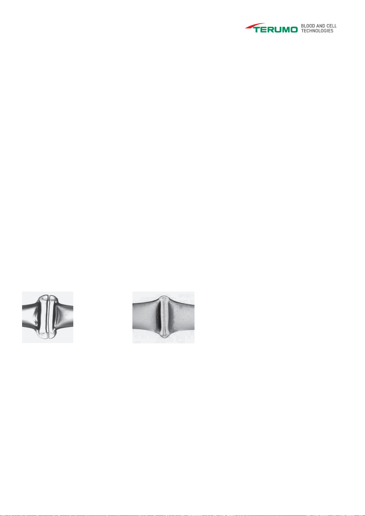
4. Lift up the sealed tube and verify that it matches the pattern shown in the photo below.
5. The center of the sealed pattern is very thin, and pulling both sides will divide the tube into two pieces.
When sealing EVA tubing, use clean scissors to separate the tubing at the center of the seal.
Caution! Do not make two or more seals within 1 cm (0.39 in) of each other, because the resulting pressure in the
tube may cause microscopic cracks and holes in the seals.
Caution! In the event of device malfunction (intermittent operation, poor seal quality, or the sealing time seems too
long or too short), contact your local Terumo BCT representative for assistance.
Caution! Periodically perform a visual check of the sealing pattern to ensure it matches the photo below.
Good sealing pattern Bad sealing pattern
6. Cleaning
This section gives information on the cleaning procedure and frequency for T-SEAL III, which requires minimal
maintenance for efficient operation. Follow the cleaning procedure below.
Warning! For your own safety, always turn off the power switch and disconnect the power cord.
Warning! Blood and blood products must always be treated as potentially infectious. In the event of blood leaks,
appropriate protective clothing should be worn during cleanup procedures.
After removing residual biological material, surfaces that have been in contact with blood or components must be
disinfected using a sterilizing agent, such as isopropanol 70%. Alternatively, a freshly prepared solution of diluted
sodium hypochlorite (household bleach) may be used to disinfect surfaces. Diluted solutions of 1 part bleach to 10 parts
water may be used.

UNLOCKING POTENTIAL |TERUMOBCT.COM Page 13 of 15 Version 1.0 Rev 02/2021
©2021 Terumo BCT, Inc.
Regardless of the sterilizing or disinfection solution used, remove any residue to ensure that surfaces of the equipment
are not subject to corrosion or discoloration. Discard all materials that come into contact with blood according to
institutional policies regarding disposal of biohazardous materials.
Caution! Do not disinfect or sterilize any part of T-SEAL III using an autoclave or with ethylene oxide gas. Doing so
will make the device unusable and invalidate the warranty.
Do not use chemical or abrasive cleaners such as acetone or ammonia.
Do not use sharp-edged tools for cleaning, which could damage the finish of the units.
Caution! Do not allow liquid to flow into the electronics part of the device.
6.1 Sealing Head
Cleaning may be required as a result of a blood leak or when required after inspection.
If a blood leak occurs, immediately remove the device from service and clean it completely before resuming use.
Use a soft lint-free tissue, moistened with a mild detergent, to clean the outside of the sealing head and cover.
To clean the electrodes, remove the front cover of the sealing module.
Note! The front cover can be cleaned separately. Clean both electrodes with a soft lint-free tissue moistened with a
mild detergent. Dry carefully and ensure that the electrodes are completely dry to prevent sparks.
Note! After cleaning, inspect the electrodes for damage. Attach the cover, ensuring that it snaps into position.
Note! Some sealing tests can be made before resuming use. Compare the pattern against the photo in Section 4.2.
Caution! Do not submerge the sealing unit in fluid, as it is not waterproof. Fluid will cause malfunction and tiny arcs
and will reduce the life span of the device.
7. Troubleshooting
Maintenance performed by the user is limited to substituting one device or one power cord for another, and if used in
cascade, changing the communication cable and connectors. The following information covers possible problems and
offers suggested solutions.
7.1 Sealer
Problem
Probable Cause
Recommended Action
Power on indicator doesn’t light
up green.
No voltage.
Other cause.
Check power supply.
Ensure the power switch is turned on.
Contact your local Terumo BCT
representative.
Power on indicator lights up
green, but when the tube is
inserted, the seal indicator
doesn’t light up.
Sealing unit defective.
Other cause.
Ensure the front cover is correctly in
place.
If the device is used in a cascade, replace
it with a different device.
Contact your local Terumo BCT
representative.

UNLOCKING POTENTIAL |TERUMOBCT.COM Page 14 of 15 Version 1.0 Rev 02/2021
©2021 Terumo BCT, Inc.
LED flashes red.
Sealing unit is too hot.
Turn the power switch off and wait about
10 minutes, and then try again.
If the LED is still flashing, contact your
local Terumo BCT representative.
LED doesn’t light.
Sealing unit defective.
Contact your local Terumo BCT
representative.
Sealing does not start.
Wet electrodes.
Leaky or wet tube.
Blocked optic sensor.
Other cause.
Clean the electrodes as described in
Section 6.1.
Dry the tube and try again.
Clean the optic sensor.
Contact your local Terumo BCT
representative.
Tube splits or breaks during
sealing.
Tube stretched during sealing.
Seals are too close together.
Incorrect adjustment of
electrodes.
Do not stretch the tube. See Section 5.2.
Leave a minimum of 1 cm (0.39 in)
between seals.
Contact your local Terumo BCT
representative.
8. Warranty and Service
If any serious incidents occur from the use of this equipment, please report the event, as soon as possible, to the closest
Terumo office.
Information on the warranty and the service provided by Terumo BCT is listed below.
8.1 Warranty
Terumo BCT guarantees that the equipment shall be free from defects in material and workmanship when delivered to
the original purchaser. Terumo BCT´s sole obligation shall be limited to repair or replacement, at Terumo BCT´s option
and expense, of the defective part or unit for the duration of the warranty.
The warranty extends only to the original purchaser and is not assignable or transferable and shall not apply to auxiliary
equipment or disposable accessories.
Terumo BCT guarantees that the equipment is fit for the purposes and indications described in the labelling when used
in accordance with the instruction for use. Unless the equipment is used in accordance with such instructions, this
warranty is void and of no effect. No other expressed or implied warranty exists, including any warranty of
merchantability or appropriateness for a particular purpose. Terumo BCT’s sole obligation and original purchaser’s
exclusive remedy for breach of warranty shall be limited to repair or replacement at Terumo BCT´s option.
Terumo BCT shall not be liable for proximate, incidental or consequential damages. Modifications, alterations,
recalibrations or abuse, and service by other than a Terumo BCT authorized representative will void the warranty.
8.2 Service
Service Under the Warranty Period
While under Terumo BCT warranty, the instrument must not be opened by unauthorized personnel.
Contact your Terumo BCT representative for service and repair information for all T-SEAL III instruments.

UNLOCKING POTENTIAL |TERUMOBCT.COM Page 15 of 15 Version 1.0 Rev 02/2021
©2021 Terumo BCT, Inc.
The unit must be packed in its original box. To ensure prompt return, a Terumo BCT representative must be notified
before shipping any unit for repair.
When contacting Terumo BCT, please be prepared to provide the part number and serial number of the unit. A service
request number will be issued and should accompany all communications. A brief written description of the problem
should be attached to the instrument when it is returned for service.
Terumo BCT will not be responsible for unauthorized returns or for units damaged in shipment due to improper
packing.
8.3 Product Disposal
For disposal of T-SEAL III (and accessories) at the end of the calculated life cycle of 10 years, please ensure the
following:
Do not dispose of T-SEAL III as unsorted municipal waste.
Recycle the T-SEAL III separately.
Use the collection and return systems available to you.
For more information on return, recovery, or recycling of T-SEAL III, please contact your local Terumo BCT Sales
Office.

Terumo BCT, Inc.
10811 West Collins Ave.
Lakewood, Colorado 80215-4440
USA
USA Phone: 1.877.339.4228
Phone: +1.303.231.4357
Fax: +1.303.542.5215
Terumo BCT Europe N.V.
Europe, Middle East and Africa
Ikaroslaan 41
1930 Zaventem
Belgium
Phone: +32.2.715.0590
Fax: +32.2.721.0770
Terumo BCT Asia Pte. Ltd.
89 Science Park Drive
#04-25 (Lobby B)
The Rutherford
Singapore 118261
Phone: +65.6715.3778
Fax: +65.6774.1419
Terumo BCT Latin America S.A.
La Pampa 1517–12th Floor
C1428DZE
Buenos Aires
Argentina
Phone: +54.11.5530.5200
Fax: +54.11.5530.5201
Terumo BCT Japan, Inc.
Tokyo Opera City Tower 49F,
3-20-2, Nishi-Shinjuku,
Shinjuku-ku, Tokyo 163-1450,
Japan
Phone: +81.3.6743.7890
Fax: +81.3.6743.9800
Document number: D0000011338
T-Seal®III
Terumo Tube Sealing Device
Version 1.0
Operator’s Manual
©2021 Terumo BCT, Inc.
Table of contents
Other Terumo Laboratory Equipment manuals


