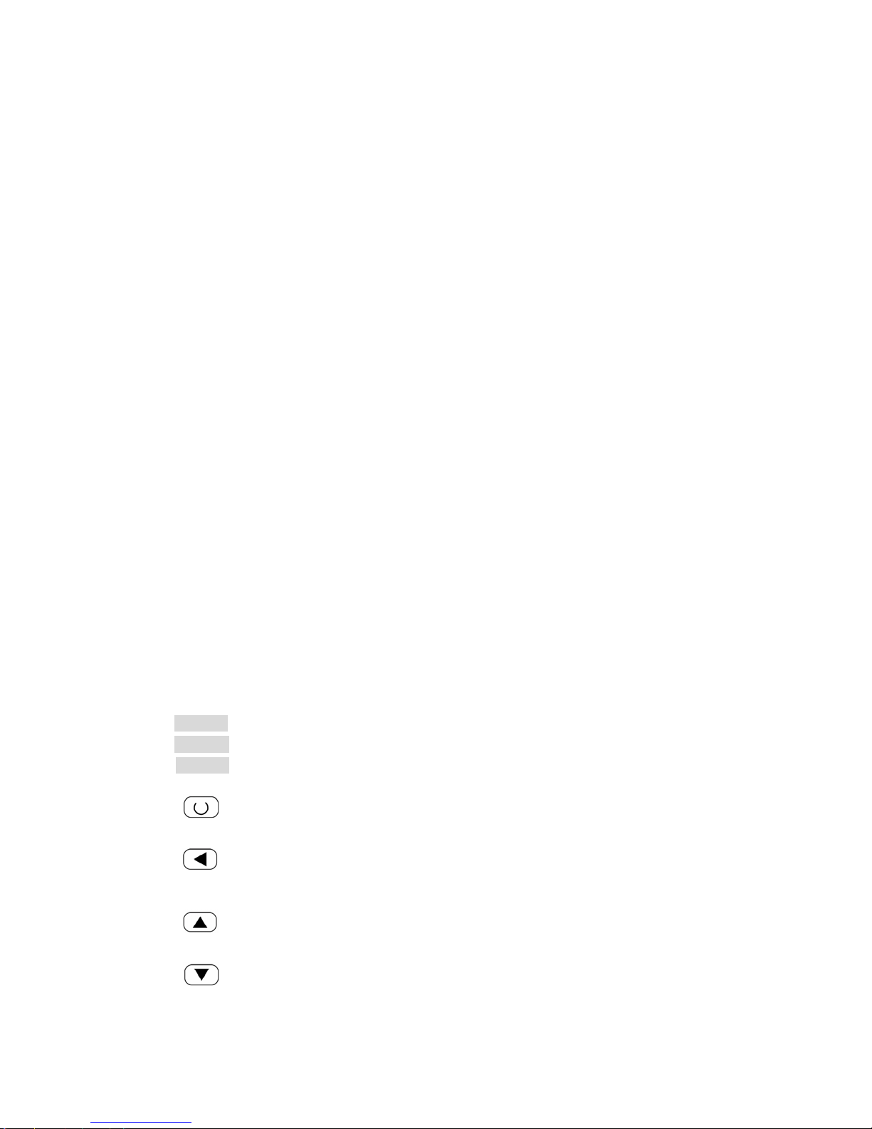
MRC WBL-MINI User manual

WBL-MINI
COOLING WATER CIRCULATOR
Operating Instructions
Operating Mamual
Before you operate the equipment please read carefully all the
instructions and safety notes. If you have any questions please phone us!
Follow the instructions on setting up, operation etc. This is the only
way to exclude incorrect operation of the equipment and to ensure full
warranty protection

1、Safety notes
· Transport the equipment with care!
· Careful transportation of the equipment requested !
· The unit may NEVER be overturned nor put upside down !
· Equipment and its internal parts can be damaged :
- by dropping
- by shock.
· Equipment should only be operated by properly instructed personnel !
· Never operate the equipment without bath liquid!
· Do not start up the equipment if
- it is damaged or leaking
- the supply cable is damaged.
· Switch off the equipment and pull out the mains plug for:
- servicing or repair
- before moving the equipment!
· Drain the bath before moving the equipment!
· Have the equipment serviced or repaired only by properly qualified
personnel!
2、Unpacking
Goods are packed carefully, largely preventing transport damage.
After unpacking , check first the equipment and accessories for possible
transport damage. If unexpectedly any damage can be noticed on the equipment it is
essential to notify the forwarding agent or the postal authorities so that an inspection
can take place.
Do not start operations with damaged instruments!
The unit may NEVER be overturned nor put upside down !
3、Equipment description
Materials
All components in contact with the thermostating liquid are made from materials
suitable for the recommended liquids and temperature. The materials used are
rustfree stainless steel, copper, brass, NBR, plastics.

Refrigeration unit
The refrigeration unit consists essentially of a fully sealed compressor. The
thermostating liquid is cooled through a heat exchanger located inside the bath. Heat
of condensation and motor heat are dissipated on air-cooled units through a
fan-cooled ribbed condenser.
The refrigeration unit is protected against overpressure and compressor overload.
With insufficient ventilation of the condenser (e.g. dirt deposits) the equipment is
switched off.
Control unit
The control unit with indication and operating functions,
The equipment is provided with a LED display to indicate the measurements and
settings as well as the operational status. The setpoint and other settings are
selected using two or three keys.
A Pt 100 temperature probe senses the outflow temperature inside the bath. The
measurement is processed by a high-resolution AD converter. Further processing
involves a special control algorithm to operate the heating triac (with reduced
reaction on the mains supply), the automatic compressor control, and the cooling
control which operates with low-noise solenoid valves. The proportional cooling
principle permits control in the cooling range without any energywasting
counter-heat.
4、Brief instructions
4.1 Assembly and setting up
It is advisable to set up the equipment so that the control unit is towards the
front and that the ventilation for the refrigeration unit, especially on equipment with
air-cooled condenser, (ventilation grille in lower part) is not impeded. Ensure a
minimum spacing of 0.5 m between ventilation grille and wall.
4.2 Filling and connection of external circuit
Fill the equipment with the appropriate circulating liquid to suit the operating
temperature. It should be filled with pure water, or a water-glycol mixture (min.
70:30%)!!
When using water as heat carrier at WBL-MINI please make sure that there
are no operating temperatures below 5°C in the outflow.
To assist in venting the pump, the pressure connection should be left open
when the equipment is filled for the first time, otherwise there may be permanent
damage to the pump!
Remove the plug on the filler opening at the upside. A funnel can be used for
filling..

When starting up for the first time, fill the bath as full as possible, up to the
max. level .
After filling up an external circuit further liquid may have to be added.
Connect the pump connections at the back of the equipment to the external
circuit. The external circuit must be pressure-tight.
Switch off the equipment before releasing the hose connections; the hose
couplings are not self-sealing!
Always ensure maximum flow cross-section in the external circuit (nipples,
tubing, external apparatus). This results in increased flow rate and therefore better
thermostating.
The equipment is designed for operation with non-flammable liquids.
Flammable liquids must not be used at temperatures higher than 25°C below the
flame point
4.3 Connection to the supply
Connect the equipment only to a supply socket with protective earth contact.
Check the details on the rating label against the supply voltage.
No warranty when the equipment is connected to the wrong supply!
4.4 Emptying
Place a container underneath the drain cock on the back of the equipment.
Switch off the equipment!
Observe the appropriate regulation when disposing of used circulating liquid.
Close the drain cock!
5、Operating panel
Key functions
① POWER Power key
② COOL Cooling Key
③ PUMP Circulating Key
④Setup key, for accessing parameter table, and confirming change.
Data shift key, also for activating auto turning
⑥Date increase key
⑦ Data decrease key

Display window
PV Process Value Display Displays PV, or code of a parameter
SV Setting Value Display Displays SV, alarming code, or value of a parameter
OPERATION DESCRIPTION
●Basal display status :
When power on, the upper display window of the instrument shows the process
value (PV), and the lower window shows the setpoint (SV). This status is called
basal display status. When the input signal is out of the measurable range (for
example, the RTD circuit is break, or input specification sets wrong), the upper
display window will alternately display “orAL” and the high limit or the low limit of PV,
and the instrument will automatically stop output.
●Set Value Setting:
In basal display status, we can set setpoint (SV) by pressing 、 、 or .
Press to decrease the value , to increase the value, and to move
to the digit expected to modify. Keep pressing or , the speed of
decreasing or inscreasing value get quick.
●Parameter Setting:
In basal display status, press and hold for about 2 seconds can access Field
Parameter Table. Pressing can go to the next parameter;pressing 、
or can modify a parameter. The instrument will escape auomatically from
the parameter table if no key is pressed within 30 seconds.
●Intelligence control and auto tuning
When At control method is chosen, the control parameters can be obtained by
running auto-tuning. At the first time of running auto-tuning, in basic display status,
“At” will flash at lower display window and the instrument executes on-off control.
After 2 to 3 cycles of on-off action, the instrument will obtain the values of PID control
parameters. If you want to escape from auto tuning status, press and hold for
about 2 seconds until the "At" flash stops. Depending on the system, the time of auto
tuning can be several seconds to several hours. After the auto tuning finishes, the
parameter “At” automatically changes to “OFF”, If user wants to run auto tuning
again, setting parameter “At” to “on”.

Note 1: Before running auto-tuning, setpoint should be set to an often-used value or middle
value first, and then start auto-tuning. Generally, for application with heating time of 10%~80%
can obtain satisfying auto-tuning result. If the heating time is not in the range of 10~80%, the
auto-tuning will run for a long time and can’t get satisfying result. Raising setpoint for heating
time less than 10% or decreasing setpoint for heating time greater than 80% can improve
auto-tuning result.
Note 2: Don’t modify the setpoint during auto-tuning. It may affect the precision of auto-tuning.
Note 3: The temperature fluctuation caused by interference may affect the precision of
auto-tuning. Besides checking the wiring, increasing the parameter FILt (input digital filter) can
also reduce interference.
Note 4: After auto-tuning finishes, generally, the temperature rising has a little over-shoot (about
1~3℃). It is because considering that the transducer is often placed between the heater and
heated material, and a little over-shoot can shorten the time of rising to setpoint and save power.
(Generally, the temperature of transducer can be raised quick than that of heated material)
6、Technical data
Specifications for WBL-MINI
Model
Parameters WBL-MINI
Temperature range@25℃0~35℃
Temperature Stability ±0.1℃
Cooling Capacity@20℃300W
Pumppressure 0.4 / 0.46bar
Pump Flow Rate 7-10 L / min
Working mode Continuous
Filling Port mm Ø25
Reservoir Capacity 4.5 L
Dimensions mm 235W×475D×490H
Power Volts Hz Amps AC220V,50Hz,10A
Shipping Weight kg 23
7、Maintenance
7.1 Cl eaning
Before cleaning the equipment, pull out the mains plug!
The unit can be cleaned with water with the addition of a few drops of a detergent
(washing-up liquid), using a moist cloth.
Water must not enter the control unit
The user is responsible for carrying out an appropriate detoxification of any
dangerous material which has been spilled on or in the unit. This applies in particular
when the unit is passed on to someone else for operation, repair, storage etc..

7.2 Maintenance of the refrigeration unit
The refrigeration unit operates largely maintenance-free. If the unit is being operated
in a dusty atmosphere the condenser of the refrigerator has to be cleaned at
intervals of 4 to 6 months or more frequently. This is best done by blowing
compressed air or nitrogen into the ventilation openings for a few minutes. It may be
useful to unscrew the front grille.
This can be done in a most suitable way by screwing off the ventilation grid, then
cleaning the condenser with a vaccuum cleaner (using the brushtop).
7.3 Repair and disposal instruction
The refrigeration unit is filled with refrigerant. Repair and disposal must only be
carried out by a qualified refrigeration technician!
Before you return the equipment for servicing it is advisable to contact our Technical
Service department.
If the equipment has to be returned to the factory, please ensure that it is carefully
and properly packed. We accepts no responsibility for damage due to unsatisfactory
packing.
7.4 About us
We are available any time for your queries, suggestions and critic
Hagavish st. Israel 58817 Tel: 972 3 5595252, Fax: 972 3 5594529 [email protected]
MRC.10.16
Table of contents
Other MRC Laboratory Equipment manuals
Popular Laboratory Equipment manuals by other brands

Waters
Waters TA Instruments Sample/Temperature Stage Operator's guide

Pall
Pall Allegro 1000 L Instructions for use

Thermo Scientific
Thermo Scientific 3960 Operating and maintenance manual

Spicer Consulting
Spicer Consulting SC22 Product guide

Nicoya
Nicoya OpenSPR Operation manual

Markes International
Markes International Kori-xr installation manual

W&H Med
W&H Med Lisa VA131-17 Instructions for use

Gerhardt
Gerhardt Vapodest 30 instruction manual

Metrohm
Metrohm 761 SD Compact IC Instructions for use

Kasanova
Kasanova KGS000001NOC instruction manual

Molecular Devices
Molecular Devices SkanStacker 300 user guide

erlab
erlab Captair Bio Smart Series user manual