TES TES-1307 User manual
Datalogging K/J Thermometer
TES-1307
INSTRUCTION MANUAL
TES ELECTRICAL ELECTRONIC CORP.
1. SAFETY INFORMATION
Read the following safety information carefully before attempting to
operate or service the meter.
Use the meter only as specified in this manual; otherwise, the protection
provided by the meter may be impaired.
Environment conditions
Altitude up to 2000 meters
Relatively humidity 80% max.
Operation Ambient 0~40℃
Safety symbols
When servicing, use only specified replacement parts.
Caution refer to this manual before using the meter.
Dangerous voltages.
Meter is protected throughout by double insulation
or reinforced insulation.
Comply with EMC
1

2. SPECIFICATIONS
2-1 General Information
Display : Dual display LCD.
Measurement Range : Type K :-190℃to 1333℃(-310℉to 2431℉)
Type J :-190℃to 760℃(-310℉to 1400℉)
Resolution : 0.1℃, 1℃, 0.1℉, 1℉.
Input Protection : 60Vdc, or 24 Vrms ac.
Sampling Rate : 1 time per second.
Memory capacity : 8000 records data, utmost 255 sets of results.
Over range indication : “OL” appears on the display.
Break or no input indication : “- - - - -” appears on the display.
Low battery indication : The is display when the battery voltage
drops below the operating voltage.
Power supply : Single 9V battery 006P 9V or IEC 6F22, or
NEDA 1604.
Battery Life : Approx. 35 hours (Alkaline battery).
Operating temperature 0℃to 40℃(32℉to 104℉) ,
and humidity : 10 –80%RH
Storage temperature -10℃to 60℃(14℉to 140℉) ,
and humidity : 10 –70%RH
Dimensions : 145mm(L) x 68mm(W) x 35mm(H)
5.7(L) x 2.7(W) x 1.4(H) inches
Weight : Approx. 235g with battery.
Accessories : Instruction manual, carry case, battery,
CD Software, RS-232 cable, 9 pin to 25 pin
gender changer.
2
2-2 Electrical Specifications
Basic Accuracy: ( @23±5℃Calibration ) Accuracy are±( ...%of
reading + degree ) at 18℃to 28℃with relative humidity up to 80%.
For single thermocouple measurements
Function
Resolution
Range
Accuracy
Type K
Type J
℃
0.1℃
-190℃~-0℃
-190℃~-0℃
±( 0.5%rdg + 0.7℃)
0℃~1000℃
0℃~760℃
±( 0.1%rdg + 0.5℃)
1.0℃
1000℃~1333℃
±( 0.2%rdg + 1℃)
℉
0.1℉
-310℉~-0℉
-310℉~-0℉
±( 0.5%rdg + 1.4℉)
0℉~999.0℉
0℉~999.0℉
±( 0.1%rdg + 1.0℉)
1.0℉
1000℉~2431℉
1000℉~1400℉
±( 0.2%rdg + 2℉)
Temperature Coefficient:
0.1 times the applicable accuracy specification per ℃from o℃to 18℃
and 28℃to 40℃( 32℉to 64℉and 82℉to 104℉).
For T1-T2 Measurements accuracy is Basic accuracy add 0.2%rdg.
NOTE
The basic accuracy specification does not include the error of the probe.
Please refer to the probe accuracy specification for additional details.
3
+

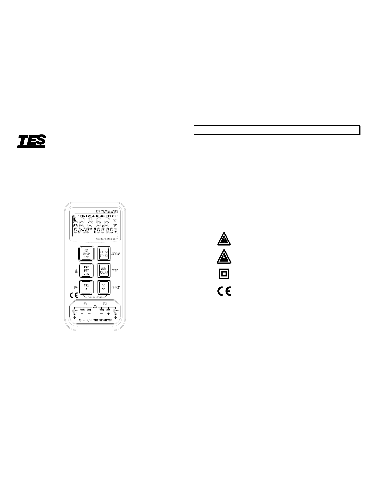
3. FRONT PANEL DESCRIPTION
(1). Display
(2). Power ON/OFF & Hold button
Press the button to turn on the thermometer.
If we press the button again, it will to enter the Data Hold mode, the “HOLD”
annunciator is displayed. When HOLD mode is selected, the thermometer
held the present readings and stops all further measurements. All button will
be disabled. If we press it again to cancel HOLD mode.
Press and hold this button for 3 seconds, it will turns the thermometer OFF.
(3). MAX/MIN/AVG
Press the button to enter the MAX/MIN/AVG with “
M
” mode, [displays
the Maximum reading with time, Minimum reading and Average reading
stored in this “
M
” 4 (memory) mode.]
a). Press the button once, the LCD will show “
M
MAX”. The timer
located at the left bottom side of LCD display will be started. The LCD
display will show the maximum temperature measurement together with
the time that had been recorded since the meter last reset.
4
b). Press the button again the LCD will show “
M
MIN”. The LCD
display will show the minimum temperature measurement together
with the time that had been recorded since the meter last reset.
c). Press the button again, the LCD will show “
M
AVG ” , “ ”.
The average of the first 10 records.
d). Press the button again, the LCD will show “
M
” , “ ”. The LCD
display will be back the original status.
e). Press and hold the button for 3 seconds, the recorded maximum and
minimum values will be cleared. The meter will be back to the
normal mode.
Note : When MAX/MIN/AVG mode is selected, except
ON
HOLD
OFF
all
function will be disabled.
The
MAX
MIN
AVG
button is only for main display use.
(4). REL/J :
Pressing this button to enter the relative mode, zero the display as a
reference value, and annunciator “ ” 0.0 is displayed. Press the
button again to exit the relative mode.
Keep pressing this button, and press
ON
HOLD
OFF
button turn on, the
thermocouple type will be set as J-type, when it is on.
Note: If
REL
J
mode is selected, except
ON
HOLD
OFF
and
REC
ERASE
button, all
function will be disabled.
When the meter is T1-T2 mode, the
REL
J
button will be disabled.
(5). T1 thermocouple input connector.
(6). T1/T2/T1-T2
When we first power the meter on, the meter main display will show T1,
and the secondary display will show T2.
If we press the button, the meter main display will show T2, and the
secondary display will show T1.
5
If we press it again, the meter main display will show T1-T2, and the
secondary display will show T1, T2, in circulation.
(7). REC/ERASE :
Data recording / reset datalogger
(8). ℃/℉:
Press this key will change the temperature scale between ℃and ℉.
(9). T2 thermocouple input connector.
(10). RS-232 interface.
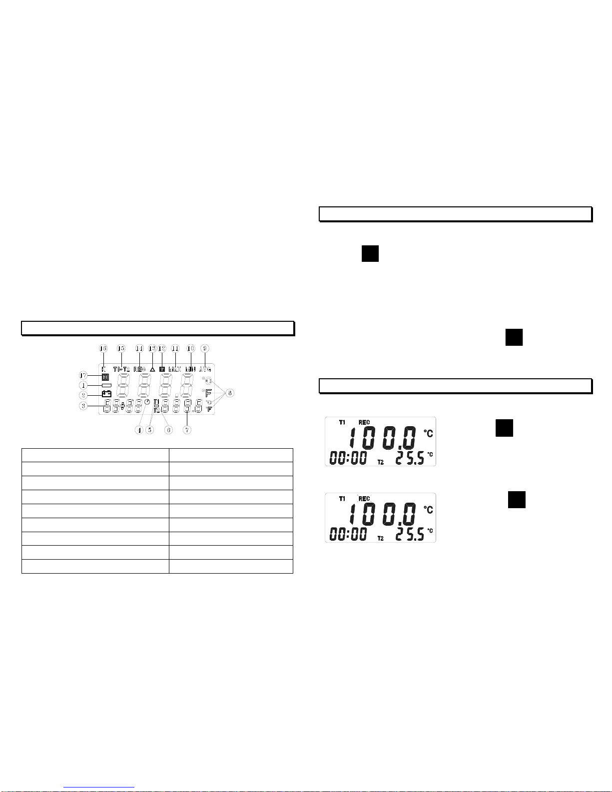
4. LCD DISPLAY DESCRIPTION
(1). Negative polarity
(10). Minimum
(2). Low battery mark
(11). Maximum
(3). Time information
(12). Memory
(4). Timer
(13). Relative mode
(5). Measure mode (secondary display)
(14). Data recording
(6). Negative polarity (secondary display)
(15). Measure mode (Main display)
(7). Measuring value (secondary display)
(16). K-Type
(8). Unit “ ℃, ℉”
(17). Hold function
(9). Average reading
6
5. OPERATION INSTRUCTIONS
(1). Plug the temperature probe into T1 or T2 input connectors.
(2). Press
ON
HOLD
OFF
button once to power on the meter. The left bottom side of
LCD will show the date and time and then time counting status.
(3). If “- - - - ” appears, it indicates no temperature probe or the probe is
broken.
(4). Input the thermocouple to measure T1 & T2 and LCD will display the value
of T1 & T2 simultaneously. If users want to obtain the difference of
T1,T2 (T1-T2), users can press the button of
T1 T2
T1-T2
. In addition, the
value of T1 & T2 will display and interchange at the right bottom side of LCD.
6. DATA RECORDING/ERASING RECORDS
(1). Record one set :
(2). Record data continuously :
7
Press
REC
ERASE
button once, and
the “REC” will be displayed.
Pressing
REC
ERASE
button for 3
seconds, “REC” flash 1 time/sec in
the display. To set the interval
time of recording, refer to page 9 .
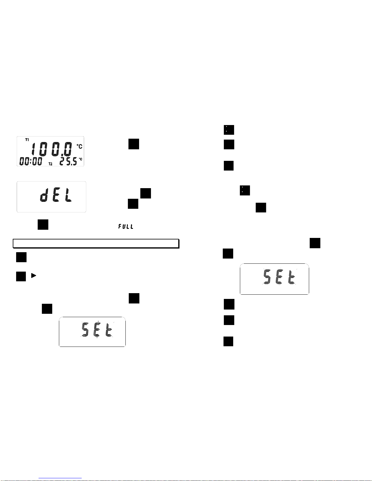
(3). Stop recording :
(4). Reset datalogger :
Note : If “
REC
ERASE
” pressed while memory is full, “ ” will display.
7. MODE SETTING
MAX
MIN
AVG
▲: Button for increasing the value of Parameters, increasing the
parameter rapid.
REL
J
: Button for moving to the desired parameter.
7-1 Date Time Setting :
Start with the power off mode. Keep pressing
T1 T2
T1-T2
button, then
press
ON
HOLD
OFF
button turn on, it will be enter setting mode.
8
Press
C
F
(clock) button enter year.
Press
MAX
MIN
AVG
button for increasing the value of parameters, increasing the
parameter rapid.
Press
REL
J
button for moving to the desired parameter.
Set sequence : yyyyMMddhhmm
Then pls press
C
F
(clock) button to save the set value. While in the set
mode, if users intend to escape from the mode and don’t want to save the
value, users can press
ON
HOLD
OFF
to end it.
※Each data you recorded will be saved together with date and time.
7-2 Set for Recording interval time
Start with the power off mode. Keep pressing
T1 T2
T1-T2
button, then
press
ON
HOLD
OFF
button turn on, it will be enter setting mode.
Press
REC
ERASE
(INTV) button to set interval time.
Press
MAX
MIN
AVG
button for increasing the value of parameters, increasing the
parameter rapid.
Press
REL
J
button to adjust the next parameter (second).
9
Press the
REC
ERASE
button again to
stop recording.
Start with the power off mode.
Keep pressing
REC
ERASE
button,
then press
ON
HOLD
OFF
button turn on,
the LCD display “dEL”.

Then pls press
REC
ERASE
(INTV) button to save the set value. While in the
set mode, if users intend to escape from the mode and don’t want to save
the value, users can press
ON
HOLD
OFF
to end it.
Note : In the set mode, if users don’t push any button in 30 seconds, then it will
escape from set mode and enter into temperature measurement mode.
8. BATTERY REPLACEMENT
(1). As battery power is not sufficient, LCD will display replacement with one
new battery type 9V is required.
(2). Press bottom cover and push in the direction of the arrow to open.
(3). Disconnect battery from instrument and replace with a standard 9-Volt
battery and replace bottom cover.
9. OPTIONAL ACCESSORY
K ( CA ) type thermocouple.
Model
Range
Tolerances
Description
TP-K01
Bead probe
-50℃to 200℃
-58℉to 392℉
±2.2℃or ±0.75%
(±3.6℉or ±0.75%)
with Teflon tape insulation.
Maximum insulating
temperature : 260℃
TP-K02
immersion
probe
-50℃to 1000℃
-58℉to 1832℉
±2.2℃or ±0.75%
(±3.6℉or ±0.75%)
3.2φ×150 ㎜metal
sheath 100 ㎝
Compensating wire
TP-K03
Surface probe
-50℃to 750℃
-58℉to 1382℉
±2.2℃or ±0.75%
(±3.6℉or ±0.75%)
100 ㎝Compensating wire
12.5φx 94 ㎜handle
10
TP-K01: Available for general condition, especially for complex
and any place hard to reach.
TP-K02: Available for temperature measurement of liquid, gels or air.
TP-K03: Available for flat or curved surface measurement.
11
+

10. RS-232 INTERFACE, SOFTWARE INSTALLATION and OPERATION
For the detailed instruction, please refer to the content of attached
CD-ROM, which has the complete instruction of RS-232 interface,
software operation and relevant information.
RS-232 protocol : are enclosed within the content of CD-ROM,
please open the CD-ROM for details.
12
TES ELECTRICAL ELECTRONIC CORP.
7F, No. 31, Lane 513, Rui Guang Road, Neihu Dist. Taipei.
Taiwan, R. O. C.
Tel : (02) 2799-3660 Fax : 886-2-2799-5099
E-Mail : tes@ms9.hinet.net http://www.tes.com.tw
Jan-2007-5
Table of contents
Other TES Thermometer manuals


