Traceable
®
is a registered trademark of Control Company ©2008 Control Company. 92-4000-01 Re . 3 051908
SPECIFICATIONS
Display: 1”, 6-Digit LCD
Ranges: –58.000 to 302.000°F / –50.000 to 150.000°C
Resolution: 0.001°
Accuracy: ± 0.05°C between 0 to 100°C
Sampling Time: approximately 4 times per second
Memories: 48 Memories are stored in the History Mode (min/max for the past
24 hours) 2 Memories are stored in the Min/Max Mode (min/max
for the current hour)
Po er: One (1) 9-Volt alkaline battery
Case: ABS plastic
Size: 3½ x 5½ x 1¼ inches
Accessories: probe (depends on model), battery,
Supplied: Traceable
®
Certificate, instructions, and data acquisition software
without cable.
Display arnings: measurements abo e or below range and low battery indicator
CONFIGURATIONS
This Traceable
®
Digital Thermometer is supplied in three different configurations. The
only difference between these configurations is the type of probe which is supplied or
used with the thermometer.
Cat. No. 4000 Supplied with a triple-purpose stainless-steel probe. Additional
probes are a ailable for this unit (see Accessories).
Cat. No. 4006 Designed to work with any YSI-400 Series probe. Supplied with a
YSI-401 General Purpose probe. The only isible difference from
the 4000 is the ¼” probe receptacle.
Cat. No. 4005 Designed to work with any YSI-400 Series probe. No probe is
pro ided with this unit. The only isible difference from the 4000 is
the ¼” probe receptacle.
NOTE: Probes are NOT interchangeable between the 4000 and the 4005/4006
because both the electrical characteristics and the probe receptacles sizes are
different.
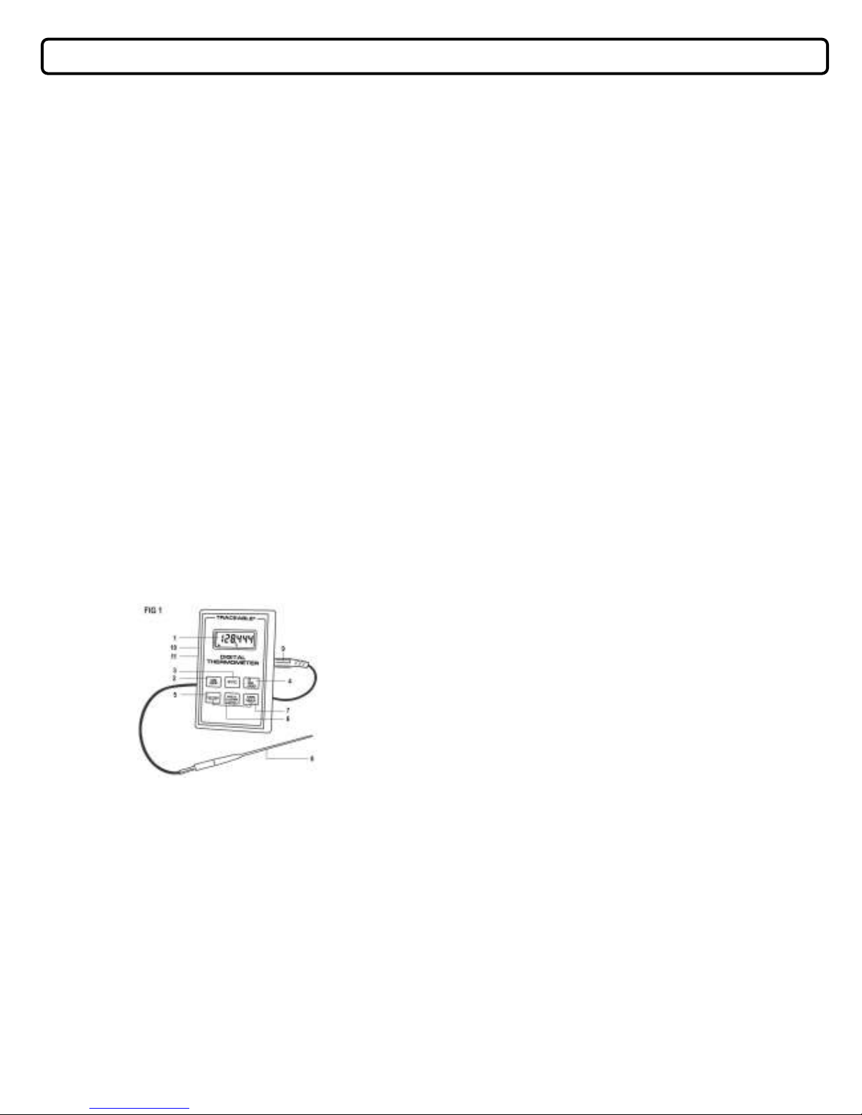
DESCRIPTION
1. Display: 6-Digits, LCD shows reading up to 0.001 resolution. ▲Arrow
indicates temperature is rising. ▼Arrow indicates temperature is
falling.
2. ON/OFF: Turns unit on and off.
3. °F/°C: Selects Fahrenheit/Celsius temperature display.
4. .0/.00/000: Selects decimal point on display for ease in reading.
5. HISTORY: Stores and displays a total of 48 memories (24 minimum and 24
maximum readings; displays the mm/max readings during the first
hour, the second hour, etc for the last 24 hours).
6. HOLD/CLEAR: Press to hold reading. Use in conjunction with history or Min/Max
keys to exit these modes or dear readings.
7. MIN/MAX: Displays the highest and lowest temperatures recorded for the
current hour.
8. Probe
9. Probe receptacle
10. AC Adaptor receptacle
11. Serial Data Cable Receptacle for Data Acquisition System
OPERATION
1. Plug the probe into the receptacle located on the right side of the unit (9, fig. 1).
2. Press the ON/OFF key (2, fig. 1) to turn the unit on.
3. Press the °F/°C key (3, fig. 1) to change the display to Fahrenheit or Celsius.
4. Press the .0/.00/.000 key (4, fig. 1) to change the display to read the desired
resolution.
5. Turn the ON/OFF key (2, fig. 1) to the “OFF” position when the thermometer is
not in use to prolong battery life.
6. Use the probe to monitor temperatures in air/gas, liquids, and semi-solids. Place
the stainless-steel portion of probe in contact with the material to be measured.
In most instances the depth of the probe needs to be approximately ½ inch.
HISTORY MODE
History pro ides an effortless method to obser e when a temperature change takes
place. It continuously displays for the past 24 hours starting with 1 hour ago. If left on
for more than 24 hours, it displays only the most recent 24 hours. History may be
re iewed at any time.
1. After 1 hour, Press HISTORY (5, fig. 1) once to show the current or first hour
reading. The display will show “1” on the far right to indicate this is the first
reading. After approximately two seconds, the display will show the temperature
and “min” which indicates this is the minimum reading for the first hour. After
approximately two more seconds, the display will again show “1”. The display
continues to alternate between these two displays. While in the history mode,
the °F/°C (3, fig. 1) or .0/.00/.000 (4, fig. 1) keys may be used to select the
desired format.
2. The second press of the HISTORY key shows the maximum temperature for the
current or first hour. After approximately two more seconds, the display will show
“1”.
3. With each press of the HISTORY key, the unit will scroll through all 48 minimum
and maximum readings.
4. To exit the history mode, press the CLEAR key (7, fig. 1) or MIN/MAX key (8, fig.
1). As long as the unit is in the history mode, pressing the CLEAR key alone will
not clear the history.
5. To clear history, first exit history mode (see 4 abo e) and then press HISTORY
and CLEAR simultaneously. Turning the unit off does not clear history.
RECALL MINIMUM/MAXIMUM
1. Press MIN/MAX (8, fig. 1) to iew the minimum and maximum temperatures
recorded since turning the unit on or since clearing min/max.
2. Press the MIN/MAX key once to display the minimum temperature. The lower
portion of the display shows “MIN” indicating that this is the minimum reading.
While in the MIN/MAX mode, select the desired format with the °F/°C (3, fig. 1)
or .0/.00/.000 (4, fig. 1) keys.
3. Press the MIN/MAX key again to display the Maximum temperature. The lower
portion of the display shows “MAX” indicating that this is the maximum reading.
A third press will return the display to the current reading.
4. MIN/MAX may be re iewed at any time.
5. To clear the MIN/MAX, place the unit in normal mode (not re iewing the
MIN/MAX) and press MIN/MAX and CLEAR simultaneously. You may also clear
MIN/MAX by turning the unit off.
HOLD FUNCTION
1. Press the HOLD key (6, fig 1) once to “freeze” the display at the current
temperature reading. “HOLD” appears on the lower portion of the display
indicating that the unit is in hold mode.
2. While in the HOLD mode, select the desired format with the °F/°C (3, fig. 1) or
.0/.00/.000 (4, fig. 1) keys.
3. Press the HOLD key a second time to return to the current temperature reading.
“HOLD” will no longer appear on the display.
POWER
Do not turn the unit on and off rapidly. It may lock the display. When turning the unit
on/off the microprocessor may become locked, inoperable, or the display may read
“888888.” If this occurs, reset the thermometer by remo ing the battery, waiting 15
seconds, and replacing the battery.


