Tesla Model S Palladium Specification sheet

TN-21-16-001 R1 Page 1 of 12
Inspect the Model S Palladium and Model X Palladium HV
Battery for Underside Damage
Tech Notes are announcements that help to communicate and track new information about Tesla Service concerns. Such
concerns may or may not be VIN specific. These instructions assume knowledge of motor vehicle and high voltage
electrical component repairs and should only be executed by trained professionals. Tesla assumes no liability for injury or
property damage due to a failure to properly follow these instructions or for repairs attempted by unqualified individuals.
Whenever the vehicle is raised, or if the customer has indicated possible damage, the underside of the vehicle, including
the High Voltage (HV) battery assembly, should be visually inspected for damage. HV battery assembly damage may
include:
•Dents, holes, cracks, or tears
•Corrosion or moisture accumulation
•Evidence of a previous thermal event, such as smoke residue, discoloration, deformation, melted seals, metallic
platter, or abnormal odor
•Rupture or disassembly
•Coolant or electrolyte leakage
NOTE: If a vehicle is brought into a Body Shop with visible damage to the bottom of the HV battery, the Body Shop
should contact Tesla:
•In Europe, Middle East, and Africa: Contact EMEABodyRepair@Tesla.com.
•All other regions: Contact your local Tesla Service Center.
The Body Shop should not try to repair the HV battery damage. Only Tesla Service Centers should try to repair the
damaged HV battery.
TN-21-16-001
December 15, 2021
Tesla, Inc.
Technical Note
Model:
Vehicle System:
Region:
Model S Palladium
Model X Palladium
16 - Battery System
All

TN-21-16-001 R1 Page 2 of 12
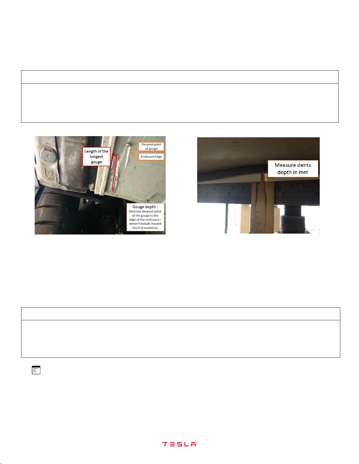
WARNING: If the HV battery is compromised with a visible open hole, crack, or tear (Figures 1 and 2), the Service
Center should not perform any additional inspections, and recommend the customer replace the HV battery. No
further diagnosis is needed as Tesla recommends an HV battery replacement for any visible open hole, crack, or tear
to meet Tesla’s standards of quality and safety.
Figure 1 –Visible open hole
Figure 2 –Visible open crack
NOTE: If at any point during the inspection the damage requires a HV battery, advise the customer that the HV
battery requires replacement to meet Tesla’s standards of quality and safety. Tesla does not recommend driving the
vehicle until the HV battery is replaced. Since the new HV battery replacement is not covered under the vehicle
warranty, the Service Center should recommend that the customer replace the HV battery and provide the customer
a price quote for the HV battery replacement. The warranty does not cover the HV battery damage because it was
caused by an external impact.
NOTE: If a replacement HV battery is recommended for any out of warranty repair and the customer declines the
repair, refer to Article 6101300 for the appropriate next actions.
WARNING: Failure to follow all High Voltage (HV) safety precautions, including the use of personal protective
equipment, when working on or around HV components may result in serious injury or property damage. Only
technicians who have completed Tesla’s Mechanical, Electrical, and Trim training course should diagnose, repair, or
replace HV components. In addition, all repair and operating instructions should be reviewed and understood before
working on Tesla vehicles or associated repair equipment.
WARNING: An HV battery poses a significant high voltage and electrocution risk if the outer enclosure or safety
circuits have been compromised or have been significantly damaged. Proper Personal Protective Equipment (PPE)
and insulating HV gloves with a minimum rating of class 0 (1000V) must be worn any time a high voltage component
is handled. Refer to Technical Note TN-15-92-003, “High Voltage Awareness Care Points” for additional safety
information.
WARNING: If the battery or vehicle displays signs of escaping gases, smoke, flames, excessive heat, sparks, or
arcing, contact the local emergency department and refer to the Emergency Response Guide, available at
http://www.tesla.com/firstresponders and/or TN-13-16-007, “Lithium-Ion Battery Emergency Response Guide, Model
S, X, 3, and Y”. Gases or smoke exiting a lithium-ion HV battery are likely flammable and could ignite at any time.
WARNING: Avoid contact with gases escaping from the battery. Vented gases might irritate the eyes, skin, and
throat. Vent gas temperatures can exceed 600ºC (1,110ºF). Contact with hot gases can cause burns.

TN-21-16-001 R1 Page 3 of 12
WARNING:
•Inspect or repair a vehicle that has an unstable battery outdoors or within easy access to the outdoors.
•If an HV battery has been determined to have a coolant leak, do not pressurize the cooling system.
•Store damaged HV batteries at least 15 m (50 ft) away from flammable materials, structures, other vehicles, and
other HV batteries.
•Do not store standalone HV batteries below -20°C (-4°F).
•Do not store standalone HV batteries for over 10 days above 35°C (95°F).
•Do not charge or discharge a standalone HV battery below 0°C (32°F).
•Do not store standalone HV batteries for over 30 days at full state of charge (SOC) or completely discharged.
•Do not charge a damaged or potentially unstable HV battery.
•Do not weld near HV batteries.
HV Battery Underside
The underside of the HV battery has several key components, as shown in Figure 3.
Figure 3 –HV Battery Components

TN-21-16-001 R1 Page 4 of 12
The bottom of the HV battery can be divided into a grid to make it easier to track and report damage (Figures 4, 5 and 6).
Figure 4 –HV Battery Grid Layout
The grid locations for the underside components of the HV battery are shown in Figure 5.
HV Battery Part
Grid Locations
Side Ski Zones
B1 –L1, B11 –L11
Baseplate
C2 –C10, E2 –E10, G2 –G10, I2 –I10,
K2 –K10
Cross Member Zones
B2 - B10, D2 –D10, F2 –F10, H2 –H10,
J2 –J10, L2 –L10
Front Skid Plate Bracket
M2 - M3, M9 - M10, N3, N9, O3 - O9
Front Ancillary
M3 –M9, N4, N7 - N8
Pyro Cover
N5 - N6
Rear Ancillary
A2 - A10
Figure 5 –HV Battery Bottom Grid

TN-21-16-001 R1 Page 5 of 12
The grid locations for the front and rear edges of the HV battery are shown in Figure 6.
HV Battery Part
Grid Locations
---
Front Skid Plate Bracket
O13 - O15
Front Ancillary
O13 - O15
---
Rear Aeroshield Bracket
A18 - A20
Rear Ancillary
A18 - A20
Figure 6 –HV Battery Edge Grid
If there is noticeable damage to the bottom of the HV battery assembly:
1. Create a Toolbox session with Article 5402800 marked as an issue.
2. Add the comment “@NACompromisedBattery”, “@EUCompromisedBattery”, or “@APACCompromisedBattery”,
depending on your region, to add HV battery inspection engineers as watchers.
3. Collect the following information and upload it to the session:
a. Several pictures of the damage, taken with a high-resolution camera: If there isn’t a visible open hole, crack,
or tear, measure the depth of the HV battery enclosure damage (Figure 7) while wearing proper PPE. If the
damage is not obvious, take an overall picture of the HV battery, with pointers to the damaged area or areas.
Figure 7 –Measuring the depth of enclosure damage
b. Information from the customer about the incident that may have caused the damage, if available.
c. The location of the damage according to the corresponding zone.
4. Perform the appropriate repair according to the corresponding section below.

TN-21-16-001 R1 Page 6 of 12
Front Skidplate
The front skidplate (Figure 8) is located at the front of the HV battery and sits over the front skidplate bracket (Figure 9):
Figure 8 –Front Skidplate
Figure 9 –Front Skidplate Bracket Location
To inspect the front skidplate for damage:
1. Visually inspect the skidplate for tears, dents, or breaches (Figure 10).
2. Remove the front skidplate (refer to Service Manual procedure 30011002; Model S, Model X).
Figure 10 –Front Skidplate Fasteners
3. Inspect the HV cables and passthroughs.
4. If there is damage to the leading edge above the front skidplate, see also “Leading Edge”section.
5. If there is damage to that extends onto the pyro cover, see also “Pyrotechnic Fuse Cover” section.

TN-21-16-001 R1 Page 7 of 12
6. If there is damage that extends onto the front ancillary, see also “Front Ancillary” section.
7. Remove and assess damage to components: HV cables, passthroughs, fasteners, baseplate, etc.
Suggest repair to customer:
•Deburr the area with a hand deburring tool to remove the sharp edges if sharp edges are found.
•Recommend the replacement of the front skidplate if the frontskid plate, or part of the skidplate, is detached.
•Recommend the replacement of the HV cables if the HV cables are damaged above the front skidplate.
•Recommend the replacement of the passthrough if a passthrough is damaged above the front skidplate.
•Recommend the replacement of the fastener if a fastener attaching the front skidplate to the vehicle is damaged
or stripped.
•Re-tap the fastener hole if a fastener hole is damaged and the fastener cannot withstand full torque.
•Recommend HV battery replacement if:
oThe HV battery enclosure fails the leak test due to impact.
oThe HV battery enclosure has low isolation due to impact.
NOTE: Do not drill new holes in any part of the HV battery case, front skidplate, rails, or baseplate.
Side Skis
There are two side skis (Figure 11). For each side ski, there is a “side ski zone,” which extends 5 inches (127 mm) inward
from the edge of the HV battery.
Figure 11 –Side Skis

TN-21-16-001 R1 Page 8 of 12
Suggest repair to customer:
•Recommend HV battery replacement if:
oThe side ski, or part of the ski, is detached from the HV battery.
oThe HV battery enclosure fails the leak test due to impact.
oThe HV battery enclosure has low isolation due to impact.
•Recommend the replacement of the jack pad if a jack pad has extensive damage where it cannot be used to
safely lift the vehicle.
•Re-tap fastener hole if a fastener hole is damaged and the fastener cannot withstand full torque.
•Deburr the area with a hand deburring tool to remove the sharp edges if sharp edges are found (Figure 12).
Figure 12 –Deburr the area to remove sharp edges
Baseplate
The baseplate covers the underside of the HV battery. The baseplate is divided into the cross member and module zones
(Figure 13):
Figure 13 –Baseplate Zones
NOTE: If damages on a module zone extend to the cross member zone, see also “Baseplate –Cross Member
Zone”section below.

TN-21-16-001 R1 Page 9 of 12
Baseplate –Module Zone
Baseplate module zones are located between the crossmember zones. When a baseplate module zone is damaged,
follow these steps:
Suggest repair to customer:
•Deburr the area with a hand deburring tool to remove the sharp edges if sharp edges are found (Figure 14).
•Recommend HV battery replacement if:
oA dent is 7 mm or more in depth (Figure 15).
oThe HV battery enclosure fails the leak test due to impact.
oThe HV battery enclosure has low isolation due to impact.
Figure 14 –Debur area to remove sharp edges
Figure 15 –Dents in the Baseplate
Baseplate –Cross Member Zone
Baseplate cross member zones separate the baseplate module zones. When a baseplate cross member zone is
damaged, follow these steps:
Suggest repair to customer:
•Deburr the area with a hand deburring tool to remove the sharp edges if sharp edges are found (Figure 14).
•Recommend HV battery replacement if
oA dent is 3 mm or more in depth (Figure 15).
oThe HV battery enclosure fails the leak test due to impact.
oThe HV battery enclosure has low isolation due to impact.
NOTE: The rear aero shield bracket, rear ancillary, front ancillary, and pyro cover zones are not included in the
baseplate area. See those specific sections if they are damaged.

TN-21-16-001 R1 Page 10 of 12
Leading Edge
The leading edge of the HV battery is above the front skidplate bracket, shown as a dashed red line (Figure 16). Anything
below the front skidplate bracket is part of the front ancillary or the pyro cover. When the leading edge area is damaged,
follow these steps:
Figure 16 –Leading Edge
Suggest repair to customer:
•Deburr the area with a hand deburring tool to remove the sharp edges if sharp edges are found.
•Recommend the replacement of the HV cables if the HV cables are damaged above the front skidplate.
•Recommend the replacement of the passthrough if a passthrough is damaged above the front skidplate.
•Recommend HV battery replacement if:
oThe HV battery enclosure fails the leak test due to impact.
oThe HV battery enclosure has low isolation due to impact.
Rear Edge
The rear edge of the HV battery enclosure is above the aero shield bracket, shown as a dashed red line (Figure 17).
When the rear edge area is damaged, follow these steps:
Figure 17 –Rear Edge
Suggest repair to customer:
•Deburr the area with a hand deburring tool to remove the sharp edges if sharp edges are found.
•Recommend the replacement of the HV cables if the HV cables are damaged above the aero shield bracket.
•Recommend HV battery replacement if:
oA passthrough is damaged above the aero shield bracket.
oThe HV battery enclosure fails the leak test due to impact.
oThe HV battery enclosure has low isolation due to impact.

TN-21-16-001 R1 Page 11 of 12
Pyrotechnic Fuse Cover
The pyrotechnic fuse cover is boxed below in the yellow dashed line (Figure 18). When the pyrotechnic fuse cover area is
damaged, follow these steps:
Figure 18 –Pyro Cover
NOTE: If damages on a pyrotechnic fuse cover section extend onto the front ancillary, follow these steps.
Suggest repair to customer:
•Recommend the replacement of the pyrotechnic fuse cover if the pyrotechnic fuse cover is missing, detached,
damaged, or something is lodged between the cover and front ancillary.
•Deburr the area with a hand deburring tool to remove the sharp edges If sharp edges are found.
Front Ancillary
The front ancillary is marked in red below (Figure 19). The pyrotechnic fuse cover area, yellow dashed box, is NOT part of
this area. If damages on the front ancillary area extend onto the pyrotechnic fuse cover area, see also the “Pyrotechnic
Fuse Cover”section above. When the front ancillary area is damaged, follow these steps:
Figure 19 –Front Ancillary

TN-21-16-001 R1 Page 12 of 12
Suggest repair to customer:
•Deburr the area with a hand deburring tool to remove the sharp edges If sharp edges are found.
•Recommend HV battery replacement if:
oThe HV battery enclosure fails the leak test due to impact.
oThe HV battery enclosure has low isolation due to impact.
Rear Ancillary
The rear ancillary area is identified with a red box in Figure 20. When the rear ancillary area is damaged, follow the steps
below:
Figure 20 –Rear Ancillary
Suggest repair to customer:
•Deburr the area with a hand deburring tool to remove the sharp edges If sharp edges are found.
•Recommend HV battery replacement if:
oThe HV battery enclosure fails the leak test due to impact.
oThe HV battery enclosure has low isolation due to impact.
This manual suits for next models
1
Table of contents
Other Tesla Automobile manuals

Tesla
Tesla MODEL Y 2022 User manual

Tesla
Tesla S 2012 User manual

Tesla
Tesla MODEL X 2015 User manual

Tesla
Tesla MODEL 3 2020 User manual

Tesla
Tesla MODEL S User manual

Tesla
Tesla MODEL S User manual

Tesla
Tesla MODEL S User manual

Tesla
Tesla X 2015-2020 User manual

Tesla
Tesla S 2017 User manual

Tesla
Tesla Roadster 2 User manual

Tesla
Tesla MODEL S 2021 User manual

Tesla
Tesla MODEL S User manual

Tesla
Tesla X User manual

Tesla
Tesla MODEL 3 2012 User manual

Tesla
Tesla Feature 3 User manual

Tesla
Tesla MODEL 3 2020 User manual

Tesla
Tesla 2010 Roadster User manual

Tesla
Tesla MODEL 3 2012 User manual

Tesla
Tesla Y 2020 User manual

Tesla
Tesla MODEL S Service manual